BTA-30A Manual - Bi-Directional Reentrant Horn Loudspeaker
BTA-30A Manual - Bi-Directional Reentrant Horn Loudspeaker
BTA-30A Manual - Bi-Directional Reentrant Horn Loudspeaker

You also want an ePaper? Increase the reach of your titles
YUMPU automatically turns print PDFs into web optimized ePapers that Google loves.
<strong>Bi</strong>-<strong>Directional</strong> <strong>Reentrant</strong><br />
<strong>Horn</strong> <strong>Loudspeaker</strong><br />
Speaker Assembly<br />
The bi-directional speaker must be assembled prior to installation. See Figure 3 on the back of this sheet for speaker assembly<br />
information. Make sure to place the washer/seals where indicated and hand tighten the various components - do not use pliers<br />
or similar tools.<br />
Speaker Installation<br />
STEP 1 - For easier installation, remove the flange (base) from the speaker<br />
by unscrewing the wing nut while at the same time pressing inwardly on<br />
the wing nut. Place the flange flush with the mounting surface and mark the<br />
location of the three holes with either a marker or punch. It is important<br />
that the three holes be exactly aligned with the flange, otherwise you might<br />
stress the base or make the connection unsteady (see Figure 1).<br />
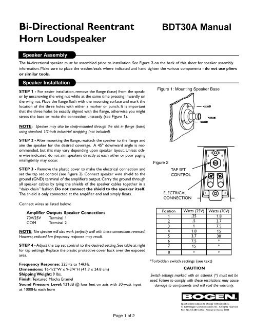
Figure 1: Mounting Speaker Base<br />
NOTE: Speaker may also be strap-mounted through the slot in flange (base)<br />
using standard 1/2-inch industrial strapping (not included).<br />
STEP 2 - After mounting the flange, reattach the speaker to the flange and<br />
aim the speaker for the desired coverage. A 45 o downward angle is recommended,<br />
but this may vary depending upon speaker layout. Unless otherwise<br />
indicated, do not aim speakers directly at each other or poor paging<br />
intelligibility may occur.<br />
STEP 3 - Remove the plastic cover to make the electrical connection and<br />
set the tap set control (see Figure 2). Connect speaker wire shield to the<br />
ground (GND) terminal of the amplifier’s output. Carry the ground through<br />
all speaker cables by tying the shields of the speaker cables together in a<br />
“daisy chain” fashion. Do not connect the shield to the speaker itself.<br />
The shield is only connected at the amplifier end and simply floats.<br />
Connect wires as listed below:<br />
Amplifier Outputs Speaker Connections<br />
70V/25V Terminal 1<br />
COM Terminal 2<br />
NOTE: The speaker will also work perfectly well with these connections reversed.<br />
However, reduced low frequency response may result.<br />
STEP 4 - Adjust the tap set control to the desired setting. See table at right<br />
for tap settings. Replace the plastic protective cover back over the exposed<br />
area.<br />
Frequency Response: 225Hz to 14kHz<br />
Dimensions: 16-1/2”W x 9-3/4”H (41.9 x 24.8 cm)<br />
Shipping Weight: 9 lbs.<br />
Finish: Textured Mocha Enamel<br />
Sound Pressure Level: 121dB @ four feet on axis with 30-watt input<br />
at 1000Hz each horn<br />
Figure 2<br />
TAP SET<br />
CONTROL<br />
ELECTRICAL<br />
CONNECTION<br />
Position<br />
1<br />
2<br />
3<br />
4<br />
5<br />
6<br />
7<br />
Watts (25V)<br />
.25<br />
.5<br />
1<br />
1.8<br />
3.7<br />
7.5<br />
15<br />
Watts (70V)<br />
1.8<br />
3.7<br />
7.5<br />
15<br />
30<br />
*<br />
*<br />
8 * *<br />
*Forbidden switch settings (see text)<br />
CAUTION<br />
Switch settings marked with an asterisk (*) must not be<br />
used. Failure to comply with these restrictions may cause<br />
damage to components and will void the warranty.<br />
Page 1 of 2<br />
Specifications subject to change without notice.<br />
© 2000 Bogen Communications Inc. All rights reserved.<br />
Part No. 54-5841-01r2 Printed in Korea 0003
XX<br />
X<br />
Figure 3: Speaker Assembly<br />
1-5/16" DIA<br />
GREY FIBER WASHER<br />
1-7/8" DIA<br />
PAPER GASKET<br />
1-7/8" DIA<br />
STEEL WASHER<br />
1-7/8" DIA<br />
PAPER GASKET<br />
THUMB<br />
SCREW<br />
1-7/8" DIA<br />
PAPER GASKET<br />
1-5/16" DIA<br />
GREY FIBER WASHER<br />
Figure 4: Assembled Speaker<br />
X X<br />
XXX<br />
X<br />
1-5/16" DIA<br />
BLACK RUBBER WASHER<br />
AFTER ASSEMBLY, ALIGN LOGO<br />
AND TIGHTEN SCREW<br />
NOTE: Extra gaskets may be included in hardware pack.<br />
X XX<br />
AFTER ASSEMBLY,<br />
ALIGN LOGO AND<br />
TIGHTEN SCREWS<br />
Page 2 of 2<br />
50 Spring Street, Ramsey, New Jersey 07446<br />
Tel. 201-934-8500, Fax: 201-934-9832<br />
Web Site: www.bogen.com