DFT120 Manual - Digital Feedback Terminator - Business Telecom ...
DFT120 Manual - Digital Feedback Terminator - Business Telecom ...
DFT120 Manual - Digital Feedback Terminator - Business Telecom ...

Create successful ePaper yourself
Turn your PDF publications into a flip-book with our unique Google optimized e-Paper software.
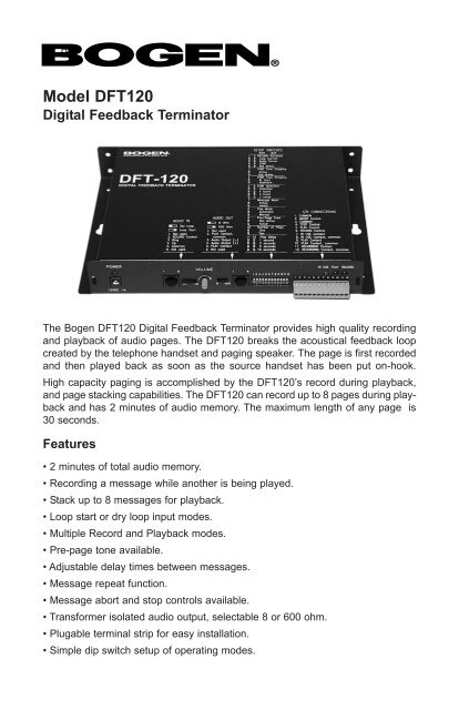
Model <strong>DFT120</strong><br />
<strong>Digital</strong> <strong>Feedback</strong> <strong>Terminator</strong><br />
The Bogen <strong>DFT120</strong> <strong>Digital</strong> <strong>Feedback</strong> <strong>Terminator</strong> provides high quality recording<br />
and playback of audio pages. The <strong>DFT120</strong> breaks the acoustical feedback loop<br />
created by the telephone handset and paging speaker. The page is first recorded<br />
and then played back as soon as the source handset has been put on-hook.<br />
High capacity paging is accomplished by the <strong>DFT120</strong>’s record during playback,<br />
and page stacking capabilities. The <strong>DFT120</strong> can record up to 8 pages during playback<br />
and has 2 minutes of audio memory. The maximum length of any page is<br />
30 seconds.<br />
Features<br />
• 2 minutes of total audio memory.<br />
• Recording a message while another is being played.<br />
• Stack up to 8 messages for playback.<br />
• Loop start or dry loop input modes.<br />
• Multiple Record and Playback modes.<br />
• Pre-page tone available.<br />
• Adjustable delay times between messages.<br />
• Message repeat function.<br />
• Message abort and stop controls available.<br />
• Transformer isolated audio output, selectable 8 or 600 ohm.<br />
• Plugable terminal strip for easy installation.<br />
• Simple dip switch setup of operating modes.
© 1998 Bogen Communications, Inc.<br />
50 Spring St., Ramsey, NJ 07446<br />
54-5036-02<br />
9902 Printed in USA<br />
All rights are reserved. No part of this document may be photocopied, reproduced,<br />
or translated to another language without the prior written consent of<br />
Bogen Communications Inc.<br />
Notice: The information contained in this document is subject to change without<br />
notice and should not be construed as a commitment by Bogen<br />
Communications, Inc.<br />
Bogen Communications, Inc. assumes no responsibility for any errors that<br />
may appear in this document nor does it make expressed or implied warranty<br />
of any kind with regard to this material, including, but not limited to,<br />
the implied warranties of merchantability and fitness for a particular purpose.<br />
Bogen Communications Inc. shall not be liable for incidental or consequential<br />
damages in connection with, or arising out of the furnishing, performance, or<br />
use of this document and the equipment which it describes.<br />
Warning: Changes or modifications to this unit not expressly approved by the<br />
party responsible for compliance could void the user’s authority to operate the<br />
equipment.<br />
Bogen® is a registered trademark of Bogen Communications, Inc.
Contents<br />
General Safety Instructions . . . . . . . . . . . . . . . . . . . . .2<br />
Callouts . . . . . . . . . . . . . . . . . . . . . . . . . . . . . . . . . . . . . .3<br />
Packing List . . . . . . . . . . . . . . . . . . . . . . . . . . . . . . . . . .3<br />
Audio Connections<br />
Audio Input Connections . . . . . . . . . . . . . . . . . . . . . .4<br />
Audio Output Connections . . . . . . . . . . . . . . . . . . . .4<br />
Control & Status Connections<br />
Control Input Connections . . . . . . . . . . . . . . . . . . . . .5<br />
Status Connections . . . . . . . . . . . . . . . . . . . . . . . . . .6<br />
Changing Status Contacts . . . . . . . . . . . . . . . . . . . . .6<br />
Settings and Controls<br />
Output Volume . . . . . . . . . . . . . . . . . . . . . . . . . . . . . .7<br />
Mode Setting Dip Switches . . . . . . . . . . . . . . . . . . . .7<br />
Operation<br />
General Operation . . . . . . . . . . . . . . . . . . . . . . . . . . .9<br />
Record Activation . . . . . . . . . . . . . . . . . . . . . . . . . . . .10<br />
Playback Control . . . . . . . . . . . . . . . . . . . . . . . . . . . .10<br />
System Connection Diagrams<br />
Loop Start Trunk & PCM2000 . . . . . . . . . . . . . . . . . .12<br />
Analog Ring Up Line & PCM2000 . . . . . . . . . . . . . . .13<br />
Page Port Interface & PCM2000 . . . . . . . . . . . . . . . .14<br />
Specifications . . . . . . . . . . . . . . . . . . . . . . . . . . . . . . . . .15<br />
Warranty & Service . . . . . . . . . . . . . . . . . . . . . . . . . . . .16<br />
1
General Safety Instructions<br />
Follow these basic safety precautions when using the system:<br />
1. Read carefully and understand all instructions.<br />
2. Follow all warnings and instructions marked on the product.<br />
3. DO NOT place the product in a closed enclosure or cabinet unless<br />
proper ventilation is provided.<br />
4. Never spill liquid on the product or drop objects into the ventilation<br />
slots and openings. Doing so my result in serious damage to the<br />
components.<br />
5. Repair or service must be performed by a factory authorized repair<br />
facility.<br />
6. Use the provided UL/CSA approved power pack.<br />
7. DO NOT staple or otherwise attach the power supply cord to<br />
building surface.<br />
8. DO NOT use the product near or in wet or damp places, such as<br />
wet basements.<br />
9. DO NOT use extension cord. Install within 6 feet of a grounded<br />
outlet receptacle.<br />
10. DO NOT install during lightning storm.<br />
11. Never touch un-insulated wires or terminals unless the unit is<br />
disconnected from both power and the rest of the phone system.<br />
12. Use Caution when installing or modifying control lines.<br />
13. The unit must be securely attached to a wall board, rack or<br />
table-mounted.<br />
CAUTION<br />
If any wiring from the system leaves the building premises,<br />
you must use proper electrical protectors.<br />
FCC Notice<br />
This equipment has been tested and found to comply with the limits for a Class<br />
A digital device, pursuant to Part 15 of the FCC Rules. These limits are<br />
designed to provide reasonable protection against harmful interference when<br />
the equipment is operated in a commercial environment. This equipment generates,<br />
uses, and can radiate radio frequency energy and, if not installed and<br />
used in accordance with the instruction manual, may cause harmful interference<br />
to radio communications. Operation of this equipment in a residential area is<br />
likely to cause harmful interference in which case the user will be required to<br />
correct the interference at the user’s own expense.<br />
2
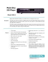
Callouts<br />
1<br />
2 3<br />
4<br />
5<br />
6 7 8 9<br />
10<br />
1. POWER - Green LED indicates unit is receiving power.<br />
2. AUDIO IN - RJ11 jack for both loop start audio and dry audio input sources.<br />
3. Output Impedance Selector - Select either 600 ohm @ +4dBm or 8 ohms<br />
@ 0.125 Watts.<br />
4. AUDIO OUT - RJ11 jack for audio output signal and status contact.<br />
5. Unit Status Indicators - Indicates whether the unit is “in-use” and if it is<br />
recording or playing back a message.<br />
6. DC Power Supply Jack - 12VDC supply connects to this jack.<br />
7. Input Type Selector - Selects either loop start (LS) or dry loop (DL) audio<br />
input type.<br />
8. VOLUME - Output volume control.<br />
9. Setup Switches - Dip switch settings control unit feature operation.<br />
10. I/O Connector - Various control inputs and status outputs are available at<br />
this connector. All I/O connections are electrically isolated<br />
from the unit’s chassis.<br />
Packing List<br />
The following items are included in the <strong>DFT120</strong> package:<br />
1 - <strong>DFT120</strong> Unit<br />
1 - Power Supply (12VDC, 1A)<br />
1 - User’s <strong>Manual</strong><br />
2 - Mounting Screws<br />
3
Audio Connections<br />
Audio Input Connections<br />
RJ11 style connector, 6 Position:<br />
1. Not used.<br />
2. Common for Record control<br />
input (pin 5).<br />
3. Ring / Audio in<br />
4. Tip / Audio in<br />
5. Record control input, connect to<br />
ground (pin 2) to start page<br />
recording.<br />
6. Not used.<br />
Input Mode Switch:<br />
DL - Dry Loop position. For operation with phone system paging ports.<br />
Requires dry contact output (connects to pins 2 & 5) for controlling<br />
the recording of pages and a dry audio (no DC voltage) source<br />
(connected to pins 3 & 4). If contact closure is not available, DTMF<br />
or Audio start features can be used to control recoding, see page 7<br />
for details.<br />
LS - Loop Start position. For operation with Loop start trunks and<br />
systems that require loop current to operate. Loop current draw from<br />
the <strong>DFT120</strong> will start the recording (connect to pins 3 & 4). See page<br />
7 for details.<br />
Audio Output Connections<br />
RJ11 style connector, 6 Position.<br />
1. Not used.<br />
2. Play status contact common<br />
3. Audio Output (-)<br />
4. Audio Output (+)<br />
5. Play status contact<br />
6. Not used<br />
Note: Play status contact changes states when the unit is playing a page.<br />
Type of closure (normally open or closed) is selectable, see page 6<br />
for details.<br />
Output Impedance Switch:<br />
8 - 8 Ohm position. Will supply up to 0.125 watts of output signal<br />
(transformer isolated) into an 8 ohm load (connect to pins 3 & 4).<br />
600 - 600 Ohm position. Will supply up to +4dBm of output signal<br />
(transformer isolated) into a 600 ohm input (connect to pins 3 & 4).<br />
4
Control & Status Connections<br />
Control Input Connections<br />
These control inputs allow external devices<br />
or switches to control the operation of the<br />
unit. No connections to these controls<br />
required when the unit is set for Automatic<br />
Playback (see “Play mode” setting, page 8).<br />
All Controls Inputs are optically coupled for<br />
electrical isolation.<br />
COMMON (Terminals 1 & 3)<br />
All control inputs are operated by connecting them to one of the COMMON<br />
terminals.<br />
ABORT (Terminal 2)<br />
When the ABORT input is activated, the message which is being recorded<br />
will be immediately halted, any recorded data discarded, and the busy-back<br />
tone sent to at the audio input. The busy back tone will be output for as<br />
long as this ABORT input is held active.<br />
Note: The ABORT input has no effect on the playback of messages.<br />
STOP (Terminal 4)<br />
When the STOP input is activated, any messages being played will be<br />
stopped and discarded. If there is another message in the stack, it will be<br />
played next. The STOP command has no effect on the record process. If<br />
the unit is recording at the same time it is playing, a STOP command will<br />
only stop the currently playing message, the recording process will not be<br />
affected. The unit will wait for the STOP input command to be removed<br />
before playing the next message in the stack.<br />
PLAY (Terminal 5)<br />
When the <strong>DFT120</strong> is in automatic playback mode this input will have no<br />
effect. When the manual playback mode is selected (see page 8), this input<br />
will be necessary in order to playback the messages once they are recorded.<br />
A momentary contact closure will initiate the play sequence. Other contact<br />
closures, while the unit is playing, will be ignored. A maintained connection<br />
to COMMON will cause the unit to automatically play after record.<br />
RECORD (Terminal 6)<br />
This input is also available on the Audio Input RJ11 connector. The Record<br />
input is used with a dry loop type of input. Maintaining the connection to<br />
COMMON is necessary while recording a page. When the connection is<br />
opened, the unit will immediately stop recording. The recorded message<br />
must be a minimum of one second in length, any message shorter than this<br />
will be deleted.<br />
5
Control & Status Connections<br />
Status Connections<br />
Three status contacts provide feedback about the operation of the <strong>DFT120</strong>. The<br />
contacts are electrically isolated from the rest of the unit.<br />
IN USE (Terminal 7 - Common, Terminal 8 - N/O*)<br />
This contact is active whenever the <strong>DFT120</strong> is performing any function.<br />
This includes recording, playing, pauses, delays and recording access<br />
tones.<br />
PLAYING (Terminal 9 - Common, Terminal 10 - N/O*)<br />
This contact is active while the <strong>DFT120</strong> is playing back a page. It will be<br />
active during the pause between the message repeats but not during the<br />
delays between different messages within the play sequence.<br />
RECORDING (Terminal 11 - Common, Terminal 12 - N/O*)<br />
This contact will be closed while the <strong>DFT120</strong> is actually recording audio<br />
data into memory. Because of the unit’s audio and DTMF triggering<br />
modes, the unit may not actually start recording at the same time the<br />
record control input is made active.<br />
* The contacts are set for normally open (N/O) when a function<br />
is not active and closed when the function is active. They can<br />
be changed so that they are normally closed and open when<br />
active, see below.<br />
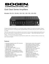
Changing Status Contacts<br />
The <strong>DFT120</strong> is factory configured with all status contacts set for normally open<br />
operation (N/O), closed when active. To change any contact:<br />
1. Disconnect the power supply and remove cover.<br />
2. Locate desired status relay (see figure below).<br />
3. Set the relay’s jumper across pins 1 & 2 for N/O operation or across<br />
pins 2 & 3 for N/C operation.<br />
4. Replace the cover and reconnect power supply.<br />
Jumper installed<br />
for N/O Operation<br />
K3<br />
In Use<br />
K2<br />
Play<br />
K1<br />
Rec<br />
Jumper installed for<br />
N/C Operation<br />
1 2 3<br />
JP-3<br />
1 2 3<br />
JP-2<br />
1 2 3<br />
JP-1<br />
6
Settings and Controls<br />
Output Volume<br />
The output volume control adjusts the level of signal<br />
reaching the input of the paging system. This<br />
control should not be set near the extremes of its<br />
rotation. Too much signal can overdrive amplifier<br />
inputs and distort DTMF tones. Too low a setting<br />
causes poor sound quality and a low signal to<br />
noise ratio.<br />
Mode Setting Dip Switches<br />
The <strong>DFT120</strong> is designed to have several functions<br />
programmed by the user. These adjustments<br />
are made by setting dip switches.<br />
The <strong>DFT120</strong> features and switch settings are<br />
described below.<br />
Note<br />
Cycle the power to the unit after making<br />
any changes to the dip switch settings.<br />
Changes will not take effect until the power<br />
has been cycled.<br />
Record Activation Method - 1,2<br />
Selects the method by which the<br />
<strong>DFT120</strong> will start recording a page<br />
message. Choose from the following:<br />
Loop current (default), Voice activation<br />
or DTMF activation.<br />
Note: Contact closure activation always<br />
available regardless of switch settings.<br />
DTMF Tone Stripping - 3<br />
Selects whether a repeated page will<br />
have any DTMF tones deleted.<br />
DTMF tones recorded at the beginning<br />
of an audio message are typically used<br />
for zone control purposes. A repeated<br />
page normally should not contain these<br />
tones.<br />
1 2 Record Activation<br />
Off Off *Loop Start<br />
Off On Audio Sense<br />
On Off DTMF<br />
On On Not Used<br />
3 DTMF Tone Stripping<br />
Off *Active<br />
On Not Active<br />
Note:<br />
Off - UP<br />
On - Down<br />
* - Factory Setting<br />
7
Settings and Controls<br />
DTMF Tone<br />
Stripping Method - 4<br />
Selects how the DTMF tones coming<br />
from the audio input during recording<br />
are handled.<br />
Tones can be stripped at the beginning<br />
only or anywhere in the message. If the<br />
tones are stripped in the middle of the<br />
message, anything recorded prior to<br />
the tones will be deleted. Only the portion<br />
of the message following the tones<br />
will be played.<br />
DTMF Allotment - 5,6<br />
Selects number of DTMF tones a message<br />
can contain.<br />
Most paging systems require a specific<br />
number of tones for paging zone selection.<br />
If more than that number of tones<br />
is detected by the <strong>DFT120</strong>, it will abort<br />
the recording.<br />
“# #" Abort Enable - 7<br />
Selects whether 2 “#” DTMF tones will<br />
cause a page recording to be aborted.<br />
This would allow a caller the ability to<br />
discard a recording and avoid having it<br />
played. The “#” button needs to be<br />
pressed twice within one second to<br />
cause the abort.<br />
PLAY Mode - 8<br />
Selects whether the <strong>DFT120</strong> will automatically<br />
play messages after they<br />
have been recorded or have an external<br />
device control playback through the<br />
uses of the PLAY control input.<br />
Pre-Page Tone - 9<br />
Selects whether a tone will be generated<br />
prior to message playback or not.<br />
This is used to alert the listeners to<br />
pages. The tone is generated before<br />
each new message playback, but not<br />
before repeats of the message.<br />
DTMF Tone<br />
4 Stripping Method<br />
Off *Strip only at start<br />
On Strip anywhere then<br />
restart recording<br />
5 6 DTMF Allotment<br />
Off Off *Unlimited<br />
Off On 4 Tones<br />
On Off 3 Tones<br />
On On 2 Tones<br />
7 “# #” Abort Enable<br />
Off *Active<br />
On Not Active<br />
8 Play Mode<br />
Off *Automatic Playback<br />
On <strong>Manual</strong> Play Control<br />
9 Pre-Page Tone<br />
Off *No Tone<br />
On Generate Tone<br />
8
Settings and Controls<br />
Number of Plays - 10<br />
Selects whether the <strong>DFT120</strong> will play a<br />
page message once or twice before<br />
moving on to the next message.<br />
Delay Between Plays - 11, 12<br />
Selects the amount of time to wait<br />
between between page message playbacks.<br />
The selected delay will be<br />
inserted between each message in the<br />
playback sequence as well as between<br />
any repeats of each messages.<br />
10 Number of Plays<br />
Off *Play page one time<br />
On Play page twice<br />
11 12 Delay Between Plays<br />
Off Off *1 Second<br />
Off On 3 Seconds<br />
On Off 5 Seconds<br />
On On 10 Seconds<br />
Operation<br />
General Operation<br />
The <strong>DFT120</strong> provides three important functions:<br />
1. Prohibits any acoustical feedback by breaking the audio loop between<br />
microphone and speaker.<br />
2. Automatically repeats each page for better intelligibility.<br />
3. Stacks up to 8 pages with the ability to record new pages while playing<br />
back previously recorded ones. This is done on a first-in first-out basis.<br />
The <strong>DFT120</strong> is designed to operated in either externally controlled or automatic<br />
modes. For most paging applications the automatic mode can be used. The<br />
automatic mode requires a minimum of installation time because it requires only<br />
2 connections, one to the paging audio source and the other to the paging system.<br />
The setup switches are factory set for the most commonly desired operating<br />
features.<br />
The <strong>DFT120</strong>’s operation can also be controlled by external equipment if necessary.<br />
A group of control inputs and status outputs provide great flexibility for<br />
interfacing with external equipment. All control inputs are opto-isolated and the<br />
status output contacts are isolated from the chassis and each other. Further<br />
flexibility is provided by allowing the condition of the status contacts to be<br />
changed from normally opened to normally closed.<br />
Another of the <strong>DFT120</strong>’s important features is its ability to detect, regenerate<br />
and strip-out DTMF tones in messages. Detecting and regenerating DTMF<br />
tones is far superior method than recording DTMF tone when zone control information<br />
needs to be included in paging messages. Stripping DTMF tones out of<br />
the message on the repeat of the page eliminates the possibility of zone control<br />
tones being heard over the paging system.<br />
9
Operation<br />
Record Activation<br />
There are several methods to initiate a recording. Changes in activation modes<br />
cannot be made without changing the particular dip switches and cycling the<br />
power supply.<br />
Loop Start, 2 Wire - The <strong>DFT120</strong> will source talk battery to the ring and tip<br />
and begin the record function when loop current draw is sensed. When<br />
loop current draw has stopped the <strong>DFT120</strong> will end the recording.<br />
Dry Loop, 4 Wire - This mode requires a separate contact closure pair to<br />
control the page recording. A second pair of wires supplies a dry audio<br />
signal (no DC voltage) to the record input.<br />
Audio Sensing - If no contact closure is available to initiate recording the<br />
audio sense mode can be used. This mode detects the presence to<br />
audio and starts recording. The recording will stop when no audio is<br />
detected for 3 seconds.<br />
DTMF Activation - If no contact closure is available to initiate recording and<br />
audio sensing is not desired (for more control over the start of recording),<br />
the DTMF activation mode can be used. Recording will begin when any<br />
DTMF tone is detected and stop when no audio is detected for 3 seconds.<br />
Playback Control<br />
The <strong>DFT120</strong> can be set to automatically play the recorded pages as soon as<br />
possible without any external intervention (Play mode dip switch, page 8).<br />
However, external control may be needed in applications where the <strong>DFT120</strong><br />
may not be the only device feeding the paging system. The external device may<br />
control either or both of the recording and the playback functions. Typically the<br />
playback function is controlled by the external device. The Play mode dip switch<br />
must be set for <strong>Manual</strong> operation to allow external devices to control playback.<br />
Recordings are initiated using any of the activation methods above, but the<br />
external device controls when they are played back. The unit will record and<br />
stack, up to 8 messages into memory, while waiting for a PLAY activation from<br />
an external device. When a “Play” activation is detected, all of the stacked<br />
pages are played in the order they were recorded.<br />
In addition to record and play control the <strong>DFT120</strong> also allows message playbacks<br />
to be stopped and recordings to be aborted.<br />
When a STOP command is detected, the unit will stop playback of the current<br />
message and drop it out of the play sequence. Once the stop command has<br />
been removed, the next message in the stack will be played in its entirety. The<br />
stop command has no effect on the recording of messages<br />
10
Operation<br />
The abort command can be used to stop and discard any message that is currently<br />
being recorded. A busy tone is sent back to the input to indicate to the<br />
person making the page that their message has been aborted. The busy tone<br />
will continue for as long as the ABORT input is active. Message playback is not<br />
affected by the use of the abort command input.<br />
11
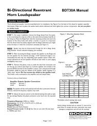
System Connection Diagrams<br />
Loop Start Trunk & PCM2000<br />
The <strong>DFT120</strong> can directly interface with a PBX loop start trunk. The input mode<br />
switch must be set to the LS position. These PBX interface connections can be<br />
used regardless of the device to which the <strong>DFT120</strong>’s output is connected. In<br />
this drawing the PCM2000 telephone input module is shown connected to the<br />
<strong>DFT120</strong> as an example.<br />
Connection of <strong>DFT120</strong> for Loop Start Trunk Access and to PCM2000<br />
12
System Connection Diagrams<br />
Analog Ring Up Line & PCM2000<br />
A TAMB telephone access module must be used to connect the <strong>DFT120</strong> to analog<br />
ring up line. The input mode switch must be set to DL position. The<br />
<strong>DFT120</strong>’s output can be connected to any paging equipment. The PCM2000 is<br />
shown here only as an example.<br />
Connection of <strong>DFT120</strong> for Analog Ring Up Access Using<br />
TAMB Interface Module and to PCM2000<br />
13
System Connection Diagrams<br />
Page Port Interface & PCM2000<br />
The <strong>DFT120</strong> interfaces directly to PBX page ports. The input slide switch must<br />
be set to DL for this application. If the page port has no contact closure, the<br />
<strong>DFT120</strong>’s VOX activation feature can be used to control recording and playback.<br />
The <strong>DFT120</strong>’s output can be connected to any paging equipment. The<br />
PCM2000 is shown here only as an example.<br />
Connection of <strong>DFT120</strong> for Page Port Access and to PCM2000<br />
14
Specifications<br />
Audio Memory Capacity: 120 Seconds<br />
Maximum Message Length: 30 Seconds<br />
Message Stacking Capacity: 8 Messages<br />
Audio Sampling: 12 Bit word at 16KHz<br />
Frequency Response: 100Hz to 6.8KHz +/-3dB<br />
Distortion: < 1.0% (THD max.)<br />
Signal-to-Noise Ratio: 60 dBr<br />
Dynamic Range: 60 dBr<br />
Audio Input:<br />
Type — Loop start trunk or 4-wire dry loop<br />
Connector — RJ-11 (6 position)<br />
Audio Output:<br />
Type — Transformer isolated, unbalanced<br />
Impedance / Power— 8 ohms / 0.125W or 600 ohms / +4dBm<br />
Connector — RJ-11 (6 position)<br />
Controls & Switches: Volume<br />
Input type (loop start / dry loop)<br />
Output impedance (8 or 600 ohm)<br />
Setup dip switches (bank of 12)<br />
External Control Inputs: Record, Play, Stop<br />
Status Outputs: Record, Play, In Use<br />
Status Contact Rating: 24VDC, 1A<br />
LED Status Indicators: Power, Play, Record, In Use<br />
Protective Fusing: 0.6A, Internal automatic reset<br />
Power Consumption: 12VDC / 350 mA (typical)<br />
Dimensions: 10”W x 1.5”H x 6.5”D<br />
Shipping Weight: 6 lbs.<br />
15
Warranty & Service<br />
Warranty<br />
Bogen Communications, Inc. warranties the <strong>DFT120</strong> against all defects in<br />
material and/or workmanship and agrees to remedy any such defect at no<br />
charge provided that the defective unit is returned, transportation prepaid, to<br />
Bogen Communications’ service department. This warranty extends for one<br />
year from data of installation or initial use, provided that this period shall not<br />
exceed 18 months from the date of manufacture. Any product which has been<br />
repaired or replaced shall be similarly warranted as to such repair or replacement<br />
for the remaining warranty period of the product originally installed or 90<br />
days from date of repair or replacement, whichever is longer.<br />
Service<br />
The Bogen <strong>DFT120</strong> is not a field serviceable product and customers are<br />
encouraged to return the product to Bogen Communications’ service department<br />
for repair. Bogen’s service department can be reached at (201) 934-8500<br />
Monday through Friday 8:30AM until 5:00PM Eastern time.<br />
If you are shipping the unit for repair under warranty, pack it in the original shipping<br />
container or similar container and ship it to the address below prepaid.<br />
Include a letter stating the problem and proof of purchase showing the purchase<br />
date. The product will be promptly repaired and returned to you freight prepaid.<br />
For service after the warranty period has expired, ship it to Bogen<br />
Communications as above. Be sure to include your name, address and telephone<br />
number in the letter. Bogen will contact you with an estimate of repairs<br />
before proceeding with any work. Return of equipment not in warranty will be at<br />
the owners expense.<br />
Bogen Communications Inc.<br />
Service Department<br />
50 Spring Street<br />
Ramsey, NJ 07446<br />
16
50 Spring Street, Ramsey, NJ 07446<br />
Tel. 201-934-8500, Fax: 201-934-9832<br />
http://www.bogen.com