Revolabs HD™ Single/Dual Wireless Microphone System
Revolabs HD™ Single/Dual Wireless Microphone System
Revolabs HD™ Single/Dual Wireless Microphone System

You also want an ePaper? Increase the reach of your titles
YUMPU automatically turns print PDFs into web optimized ePapers that Google loves.
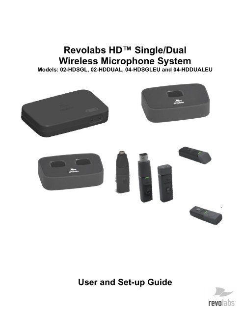
<strong>Revolabs</strong> HD <strong>Single</strong>/<strong>Dual</strong><strong>Wireless</strong> <strong>Microphone</strong> <strong>System</strong>Models: 02-HDSGL, 02-HDDUAL, 04-HDSGLEU and 04-HDDUALEUUser and Set-up Guide
© 2009 REVOLABS, INC. All rights reserved. No part of this document may be reproducedin any form or by any means without express written permission from <strong>Revolabs</strong>, Inc.Product specifications are subject to change without notice.<strong>Revolabs</strong> HD <strong>Single</strong> & <strong>Dual</strong> Manual01-HDSGLMAN-PAP-11October 2009 (Rev 1.5)
Export Law AssurancesThis product is controlled under the export regulations of the United States of America and Canada. TheGovernments of the United States of America and Canada may restrict the exportation or re-exportation of thisproduct to certain destinations. For further information contact the U.S. Department of Commerce or theCanadian Department of Foreign Affairs and International Trade. The use of wireless devices and theiraccessories may be prohibited or restricted in certain areas. Always obey the laws and regulations on the useof these products.02-HDSGL and 02-HDDUAL (1 & 2 channel systems respectively) North AmericaUPCS Usage RestrictionDue to the UPCS frequencies used, this product is licensed for operation only in the United States of Americaand Canada.04-HDSGLEU and 04-HDDUALEU (1 & 2 channel systems respectively) EuropeanUnion Usage RestrictionDue to the DECT frequencies used, this product is licensed for operation only in the European Unioncountries.European ComplianceThis equipment has been approved in accordance with Council Directive 1999/5/EC “Radio Equipment andtelecommunications Equipment.Model Numbers:04-HDSGLEU-NM04-HDDUALEU-NM03-HDEXEMICEU-1103-HDTBLMICEU-OM-1103-HDTBLMICEU-DR-1103-HDXLRMICEU-1103-HDCOMANEU-11HD <strong>Single</strong> Channel <strong>System</strong>, 1-Channel, w/o micsHD <strong>Dual</strong> Channel <strong>System</strong> 2-Channel, w/o micsHD <strong>Microphone</strong>, WearableHD <strong>Microphone</strong>, Tabletop, Omni-directionalHD <strong>Microphone</strong>, Tabletop, DirectionalHD, XLR <strong>Wireless</strong> Adapter for Dynamic Handheld <strong>Microphone</strong>HD <strong>Wireless</strong> Adapter for Countryman <strong>Microphone</strong>Standards to which Conformity is declared:RF ETSI EN 301 406 V 1.4.1 03/2001EMC ETSI EN 301 489-6 v1.2.1 (2002-04)WEEE Notification:The Waste Electrical and Electronic Equipment (WEEE) directive (2002/96/EC) is intended to promoterecycling of electrical and electronic equipment and their components at end of life.2003/11/EC & 2002/95/EC “RoHS Compliance Directive”:The products referenced herein are in compliance with the EU directive 2003/11/EC and EU directive2002/95/EC.- 2 -
IntroductionCongratulations on your purchase of a <strong>Revolabs</strong> <strong>Wireless</strong> <strong>Microphone</strong> <strong>System</strong>! This system utilizes1.9 GHz DECT technology, and high band-width audio from multiple wireless microphones, enablingclear, reliable, un-tethered communications in recording, audio/video conferencing, speechrecognition, VOIP communications, sound re-enforcement as well as many other environmentsrequiring clear audio capture.The <strong>Revolabs</strong> HD <strong>Single</strong> and <strong>Dual</strong> Channel <strong>Wireless</strong> <strong>Microphone</strong> <strong>System</strong>s have high definitionaudio, 50 Hz to 20 kHz, which allows the systems to pick up the entire human voice spectrum. TheHD <strong>Single</strong> and <strong>Dual</strong> Channel <strong>System</strong>s are a unique marriage of innovative technology and ergonomicdesign, employing Multi-Carrier Time Division Multiple Access and Time Division Duplex(MC/TDMA/TDD) radio transmissions both to and from the microphone.This technology allows the microphones to co-exist with other wireless products such as wirelessLANs (802.11b&g), and includes digital encryption technology to ensure secure communications.<strong>System</strong> ComponentsDepending on which system you’ve purchased, your <strong>Revolabs</strong> HD <strong>System</strong> contains the following:• Mountable <strong>Single</strong> or <strong>Dual</strong> Channel Base Station• <strong>Single</strong> or <strong>Dual</strong> Channel <strong>Microphone</strong> Charger Base• HD <strong>Wireless</strong> <strong>Microphone</strong>s, purchased and boxed separatelyThe Base Station houses the processor and one end of the wireless connection. It features one set ofPCB diversity antennae and offers individual line-level or mic-level audio in/out for each microphonechannel.This allows for external audio processing such as:• Mixing- 3 -
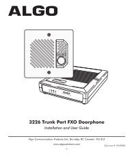
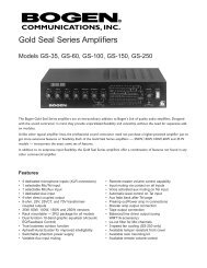
• Acoustic echo cancellation (AEC)• Feedback elimination• Level control• Equalization• Noise cancellationThe system is designed to optimize audio capture/reproduction by providing:• Consistent audio input from all participants• Minimum room noise• Mute control• <strong>Wireless</strong> encryption• Automatic channel selection• Full duplex audioThe Charger Base charges the HD <strong>Wireless</strong> <strong>Microphone</strong>s and stores them when not in use.Installing the <strong>Revolabs</strong> HD Base StationThe <strong>Revolabs</strong> HD Channel Base Station, shown below in front and rear panel views, manageswireless audio signal processing, pairing, and muting between the <strong>Revolabs</strong> microphones and theBase Station.Front View1Rear View2Controls and Connections:6 75431. Channel LED indicators: Displays microphone mute and pairing states2. Pairing Push Buttons: For pairing microphones to Base Station3. Power In Receptacle (100-240 VAC)4. 3.5mm Balanced Input Connectors5. 3.5mm Balanced Output Connectors6. Mini-USB Serial Interface7. Configuration DIP Switches (see Section Using the Rear Panel Configuration DIP switches)- 4 -
To Install the Base Station:1. Plug the power cord into an appropriate outlet2. Connect the necessary outputs and inputs<strong>Revolabs</strong> HD Base Station Audio ConnectionsThere are (2) 3.5mm balanced inputs and (2) 3.5mm balanced outputs on the back panel of the unitproviding access to each channel’s audio signal.The three terminals correspond to:Tip = Positive +Ring = Negative –Sleeve = Shielded GroundThere are one or two output channels representing a separate channel for each microphone. Themicrophone output connectors need to be attached to the input connectors of an audio mixer.The Base Station input connectors (also 0 dBu) may then be attached to mixer channel outputs.Because the system is full-duplex, the input connections provide the ability to hear program audiousing a 2.5mm earpiece attached to the microphone (supplied with the wearable microphone).Depending on the application, it is possible to feed a single audio feed back to each earpiece. Thiswould allow for translation, personal hearing assistance or other services to be incorporated into anapplication.NOTE: The USB port may exhibit static sensitivity. If the Base Station audio shuts down afterhandling, please power cycle the Base StationConfiguring the <strong>Revolabs</strong> HD TM Base StationEach <strong>Revolabs</strong> HD TM Base Station must be configured properly prior to use. Accurate configuration isdependent on several variables such as:• Is Line Level or Mic Level signal required?Refer to setting Dip Switch 3 below.• How many HD TM <strong>Dual</strong>/<strong>Single</strong> <strong>System</strong>s are being used together in close proximity?If you have more than one <strong>Revolabs</strong> <strong>Wireless</strong> <strong>Microphone</strong> <strong>System</strong>, refer to setting DipSwitch 7&8 below. Note: It is recommended that the lowest functioning Transmit Powerbe used for each system.• How large is the room?Refer to setting Dip Switch 7&8 below. Note: It is recommended that the lowestfunctioning Transmit Power be used for each system.Using the Rear Panel Configuration DIP Switchesoffon- 5 -
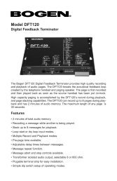
DIPSwitch1 Output MixingFeature Off (Default) OnIndividualOutputsMixed Output2 Low Pass Filter No LPF LPF3Audio OutputLevel4 Mute ModeLine LevelIndividualMutesFlatHighboostBassBoostMic LevelNo MutesDynamic5Off On Off On<strong>Microphone</strong> EQ6 Off Off On On65' 50' 30' 15'7Off On Off OnTransmit Power8 Off Off On OnConfiguration SettingsDIP Switch 1- Output Mixing:When DIP Switch 1 is OFF(default), each HD microphone has its own 3.5mm balanced audio outputon the Base Station. When DIP Switch 1 is switched on, the audio outputs of the two HDmicrophones are mixed together and sent to both outputs.DIP Switch 2 - Low Pass Filter:When DIP switch 2 is OFF(default) the microphone provides a 50 Hz-20 kHz audio bandwidth. WhenDIP switch 3 is ON, a LPF is activated taking the audio bandwidth to 50 Hz-15 kHz.DIP Switch 3 – Audio Output Level:When DIP switch 3 is OFF(default) the microphone outputs provide a line level signal~0 dBu. WhenDIP switch 3 is ON, the microphone outputs provide a mic level signal ~-40 dBu.DIP Switch 4 - Mute Mode:When DIP switch 4 is OFF(default) each microphone has its own individual muting capabilities. WhenDIP switch 4 is ON, the microphone mute buttons are deactivated resulting in the mics always beingactive and un-muted when not in the Charger Base.DIP Switch 5&6 – <strong>Microphone</strong> EQ:- 6 -
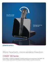
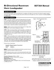
There are four EQ options for the microphone outputs of the Base Station. One of these options canbe activated for both microphones.DIP Switch 7&8 - Transmit Power:The transmit power of the Base Station can be adjusted to help reduce the operational radius of a<strong>Revolabs</strong> HD TM <strong>System</strong> in order to prevent interference from other <strong>Revolabs</strong> products, or from otherdevices operating in the same frequency.Note: It is recommended that the lowest functioning Transmit Power be used for each system.<strong>Revolabs</strong> HD <strong>Microphone</strong>s and HD <strong>Microphone</strong> AdaptersUse any of five microphones with your <strong>Revolabs</strong> HD <strong>System</strong>:• <strong>Revolabs</strong> HD Wearable <strong>Wireless</strong> <strong>Microphone</strong>• <strong>Revolabs</strong> HD Omni-directional Tabletop <strong>Wireless</strong> Boundary <strong>Microphone</strong>• <strong>Revolabs</strong> HD Uni-directional Tabletop <strong>Wireless</strong> Boundary <strong>Microphone</strong>• <strong>Revolabs</strong> HD Universal <strong>Wireless</strong> Adapter for Handheld <strong>Microphone</strong>s• <strong>Revolabs</strong> HD <strong>Wireless</strong> Adapter for Countryman <strong>Microphone</strong>sUsing the HD Wearable <strong>Wireless</strong> <strong>Microphone</strong>sThe <strong>Revolabs</strong> HD Wearable <strong>Microphone</strong>s, shown in the following figure, are paired to the BaseStation and can be worn on the user’s shirt pocket, lapel or on a lanyard. They provide high qualityfull duplex audio between each user and the conferencing or audio system.651 2431. Earpiece jack — accepts the 2.5mm plug for the earpiece.2. Charging port — docks to <strong>Revolabs</strong> HD Charger Bases.3. Pocket clip — also used to attach microphone to a lapel, blouse or lanyard.4. Mute Button — press to mute, un-mute and pair microphone.5. Acoustic Cover — protects delicate microphone element (non-removable).6. LED display — visual status for mute, un-mute, and pairing.Note: <strong>Microphone</strong>s in new systems must be paired to the Base Station with each microphoneassigned to a unique channel on the base unit. See pairing instructions below.<strong>Revolabs</strong> HD Wearable <strong>Microphone</strong>s turn on and mute automatically when removed from ChargerBase, to reduce noise while being attached.- 7 -
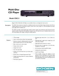
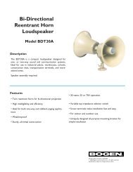
If the microphones are placed too far from the Base Station (~65 feet or 20 meters) the connectionwill be dropped (LED flashes all colors) and the microphone will mute. After 15 seconds themicrophone will beep 5 times, and will continue beeping every 30 seconds to indicating it’s out ofrange.Move the microphone closer to the Base Station and the connection will automatically be reestablishedto its original state, and the beeping will cease. If not, the microphone will continuebeeping until it turns off in about 15 minutes.Using the HD Directional Tabletop <strong>Wireless</strong> Boundary <strong>Microphone</strong>sThe HD Tabletop <strong>Wireless</strong> <strong>Microphone</strong>, shown below, is designed to provide optimum coveragewhen placed on a conference room table in front of one or two people.Pickuppatter45 4565123 41. LED display — visual status for mute, un-mute, and pairing.2. Rubber feet — non-slip, vibration absorbing pads.3. Audio jack — accepts a 2.5mm plug.4. Charging port — docks to <strong>Revolabs</strong> HD Charger Bases.5. Mute button — press to mute, un-mute and pair microphone.6. Acoustic Cover — protects microphone element (non-removable).To use the HD Directional Tabletop <strong>Microphone</strong>:1. Remove the microphone from the Charger Base to turn on and automatically mute the mic.(indicated by a flashing RED LED)2. Directional Tabletop microphones should be located on the table with the acoustic cover pointedtoward the users, trying to keep the microphone 2 to 5 feet (0.6 to 1.5m) from the target person ortwo. The pick-up pattern for this directional microphone is ~+/- 45º to either side of directly in frontof the microphone. It is always better to be as close to the person speaking as possible, but avoidplacing the microphone where it might be blocked by equipment or paperwork. Avoid placingmicrophones too close to an audio or video conference speaker to avoid echoes. Make sure thatthe microphone is always placed lying on its rubber feet atop a flat surface. Refer to diagrambelow:- 10 -
3. With the microphone in position, un-mute the microphone by pressing and releasing the Mutebutton (confirm by a flashing GREEN LED).4. To turn microphone off, return the microphone unit to the Charger Base or press and hold theMute button for ~10 seconds until the LED turns solid RED and release button.If the microphones are placed too far from the Base Station (~65 feet or 20 meters) the connectionwill be dropped (LED flashes all colors) and the microphone will mute. After 15 seconds themicrophone will beep 5 times, and will continue beeping every 30 seconds to indicating it’s out ofrange.Move the microphone closer to the Base Station and the connection will automatically be reestablishedto its original state, and the beeping will cease. If not, the microphone will continuebeeping until it turns off in about 15 minutes.Using the HD XLR <strong>Microphone</strong> <strong>Wireless</strong> AdapterThe HD <strong>Wireless</strong> XLR Adapter for Handheld <strong>Microphone</strong>, shown in the following figure, connects to ahandheld dynamic microphone for wireless freedom during open mic meetings, Q&A sessions,classrooms, etc.54311. Audio Out port — accepts the 2.5mm plug for the earpiece.2. Charging Port — docks to all <strong>Revolabs</strong> HD Charger Bases.3. Mute button — press to mute, un-mute and pair microphone.4. LED display — visual status for mute, un-mute, and pairing.5. XLR Female connector — balanced audio for dynamic microphones.2To use the HD Universal <strong>Wireless</strong> Adapter:- 11 -
1. Remove the <strong>Microphone</strong> Adapter from the Charger Base.The adapter turns on and mutes automatically when removed from Charger Base (flashing REDLED). The XLR <strong>Microphone</strong> Adapter is attached to a standard dynamic microphone to convert itfrom a wired microphone to a wireless microphone (see following figure).Note: The Adapter does not provide phantom power or bias current so it cannot be used withcondenser or electret microphones.2. With the microphone attached, un-mute the Adapter by pressing and releasing the Mute button(confirm by a flashing GREEN LED).Note: If the microphone has an on-board mute switch, this switch must also be un-muted priorto use.3. To turn the Adapter off, return the microphone unit to the Charger Base or press and hold theMute button for ~10 seconds until the LED turns solid RED then release button.Important: Always remove the microphone from the Adapter by pressing the latch switch andseparating the parts before returning the Adapter to the Charger Base.If the Adapter is moved too far from the Base Station (~65 feet or 20 meters) the connection will bedropped (LED flashes all colors) and the audio will mute. After 15 seconds the microphone will beep5 times, and will continue beeping every 30 seconds to indicate that it is out of range.Move the XLR Adapter closer to the Base Station and the connection will automatically be reestablishedto its original state, and the beeping will cease. If not, the XLR Adapter will continuebeeping until it turns off in about 15 minutes.Using the HD <strong>Wireless</strong> Adapter for Countryman <strong>Microphone</strong>The HD <strong>Wireless</strong> Adapter for Countryman <strong>Microphone</strong>s, shown in the following figure, is connects toa Countryman microphones for wireless freedom for broadcasting applications with no bulkyequipment, such as a belt pack or batteries.5- 12 -
A microphone that is not paired will be indicated by a cycling RED-GREEN LED pattern. A BaseStation channel that is not paired to a microphone will not show any activity on the channel LED(make sure unit is first powered on by observing GREEN backlit front panel display).When channels are paired, both microphone and channel LEDs will flash RED as microphones areremoved from the Charger Base and flash GREEN when un-muted. Remember that only onemicrophone can be paired to any single Base Station channel.To pair an individual microphone to the Base Station:1. Turn the microphone OFF (no LED activity). If the microphone is ON, press and hold the Mutebutton for 10 seconds until the LED turns solid RED then release the button to turn the unit off. (donot release the button when you hear two beeps).2. Place the microphone unit into pairing mode by holding the Mute button down for seven seconds.The LED will turn solid RED. Release the Mute button. The microphone is now in pairing mode.3. Within one minute, push and hold the button for the desired channel on the Base Station for sevenseconds until the LED turns solid red then release. The LED for that channel will be solid red untilpairing starts, as indicated by a quick GREEN flash, then switching to flashing RED on both themicrophone and the Base Station (muted audio). Pairing is now complete.<strong>Revolabs</strong> HD TM <strong>Single</strong> or <strong>Dual</strong> Charger BaseWhen microphones are not in use, they should be properly inserted into the <strong>Revolabs</strong> HD ChargerBase. It is important to ensure that all system microphones are inserted fully in the base so thatcharging will occur. Features of the base are shown in the following figure.3211. LED indicator — power status indicator2. Charger Bays — charges up to 2 <strong>Microphone</strong>s3. Power Cord Receptacle — power supply input, 9-24VDC (on rear)Power ModuleThe Charger Base requires 5VDC power, provided by the AC Adapter. Plug the supplied AC adapterinto an appropriate power outlet 110-240 AC, 50-60Hz. The power LED on the Charger Base willilluminate.- 14 -
Warranty<strong>Revolabs</strong>, Inc. warrants this product to be free of manufacturing defects. Repair or replacement ofany defective part or unit (at the discretion of the Seller) will be free of charge for the period of oneyear.Any attempt by the user to alter the equipment, or equipment damaged by negligence, accident, orActs of God voids this warranty.The Seller shall not be liable for any consequential damage resulting from the malfunction of thisproduct. Should the user experience unsatisfactory performance from this equipment, contact theSeller to obtain instructions for return, or replacement, as deemed necessary.This warranty is not transferable by the original end user.<strong>Revolabs</strong>, Inc.63 Great RoadMaynard, MA 01754www.revolabs.com800.326.1200- 17 -
IndexAdjusting the Volume, 8Base Station, 4Back Panel, 4Front Panel, 4Channel LED indicators, 5Channels, 5Charger Bays, 13Charging the Batteries, 13First-time use, 13Recharging, 13Connections, 5Earpiece, 5Full-Duplex, 5Indicator LEDs, 15Input Connectors, 5LED indicator, 13MC/TDMA/TDD, 3<strong>Microphone</strong>Charging port, 7Earpiece Jack, 7LED Display, 7Mute Button, 7Pocket Clip, 7<strong>Microphone</strong>s, 7Pairing, 12Power Cord Receptacle, 13Power In Receptacle, 5Power Module, 13Safety Information, 1Specifications, 17<strong>System</strong> Components, 3Base Station, 3Diversity Antennas, 3Earpieces, 3<strong>Microphone</strong> Charger Base, 3<strong>Microphone</strong> Lanyards, 3Time Division Duplex, 3Time Division Multiple Access, 3Warranty, 16<strong>Wireless</strong> Boundary <strong>Microphone</strong>, 9, 10XLR <strong>Microphone</strong> <strong>Wireless</strong> Adapter, 11- 19 -
Note: <strong>Microphone</strong>s must be fullycharged and paired to theBase Station prior to first use.<strong>Revolabs</strong> HD <strong>Single</strong> & <strong>Dual</strong> Manual01-HDSGLMAN-PAP-11October 2009 (Rev 1.3)- 20 -