Revolabs HD™ Single/Dual Wireless Microphone System
Revolabs HD™ Single/Dual Wireless Microphone System
Revolabs HD™ Single/Dual Wireless Microphone System

Create successful ePaper yourself
Turn your PDF publications into a flip-book with our unique Google optimized e-Paper software.
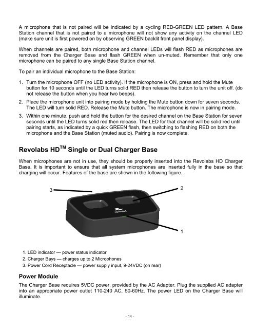
A microphone that is not paired will be indicated by a cycling RED-GREEN LED pattern. A BaseStation channel that is not paired to a microphone will not show any activity on the channel LED(make sure unit is first powered on by observing GREEN backlit front panel display).When channels are paired, both microphone and channel LEDs will flash RED as microphones areremoved from the Charger Base and flash GREEN when un-muted. Remember that only onemicrophone can be paired to any single Base Station channel.To pair an individual microphone to the Base Station:1. Turn the microphone OFF (no LED activity). If the microphone is ON, press and hold the Mutebutton for 10 seconds until the LED turns solid RED then release the button to turn the unit off. (donot release the button when you hear two beeps).2. Place the microphone unit into pairing mode by holding the Mute button down for seven seconds.The LED will turn solid RED. Release the Mute button. The microphone is now in pairing mode.3. Within one minute, push and hold the button for the desired channel on the Base Station for sevenseconds until the LED turns solid red then release. The LED for that channel will be solid red untilpairing starts, as indicated by a quick GREEN flash, then switching to flashing RED on both themicrophone and the Base Station (muted audio). Pairing is now complete.<strong>Revolabs</strong> HD TM <strong>Single</strong> or <strong>Dual</strong> Charger BaseWhen microphones are not in use, they should be properly inserted into the <strong>Revolabs</strong> HD ChargerBase. It is important to ensure that all system microphones are inserted fully in the base so thatcharging will occur. Features of the base are shown in the following figure.3211. LED indicator — power status indicator2. Charger Bays — charges up to 2 <strong>Microphone</strong>s3. Power Cord Receptacle — power supply input, 9-24VDC (on rear)Power ModuleThe Charger Base requires 5VDC power, provided by the AC Adapter. Plug the supplied AC adapterinto an appropriate power outlet 110-240 AC, 50-60Hz. The power LED on the Charger Base willilluminate.- 14 -