1 - FlowVision GmbH
1 - FlowVision GmbH
1 - FlowVision GmbH

Create successful ePaper yourself
Turn your PDF publications into a flip-book with our unique Google optimized e-Paper software.
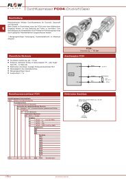
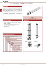
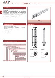
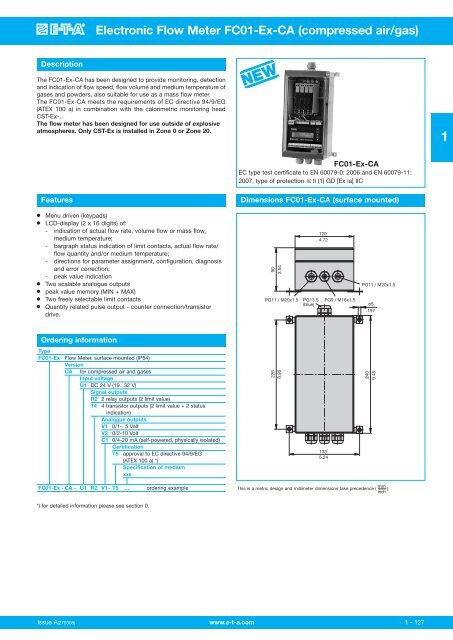
Electronic Flow Meter FC01-Ex-CA (compressed air/gas)<br />
Description<br />
The FC01-Ex-CA has been designed to provide monitoring, detection<br />
and indication of flow speed, flow volume and medium temperature of<br />
gases and powders, also suitable for use as a mass flow meter.<br />
The FC01-Ex-CA meets the requirements of EC directive 94/9/EG<br />
(ATEX 100 a) in combination with the calorimetric monitoring head<br />
CST-Ex-..<br />
The flow meter has been designed for use outside of explosive<br />
atmospheres. Only CST-Ex is installed in Zone 0 or Zone 20.<br />
NEW<br />
1<br />
FC01-Ex-CA<br />
EC type test certificate to EN 60079-0: 2006 and EN 60079-11:<br />
2007, type of protection II (1) GD [Ex ia] IIC<br />
Features<br />
Dimensions FC01-Ex-CA (surface mounted)<br />
●<br />
●<br />
●<br />
●<br />
●<br />
●<br />
Menu driven (keypads)<br />
LCD-display (2 x 16 digits) of:<br />
- indication of actual flow rate, volume flow or mass flow,<br />
medium temperature;<br />
- bargraph status indication of limit contacts, actual flow rate/<br />
flow quantity and/or medium temperature;<br />
- directions for parameter assignment, configuration, diagnosis<br />
and error correction;<br />
- peak value indication<br />
Two scalable analogue outputs<br />
peak value memory (MIN + MAX)<br />
Two freely selectable limit contacts<br />
Quantity related pulse output - counter connection/transistor<br />
drive.<br />
90<br />
3.54<br />
PG11 / M20x1.5<br />
PG13.5<br />
(blue)<br />
120<br />
4.72<br />
PG9 / M16x1.5<br />
PG11 / M20x1.5<br />
ø5<br />
.197<br />
Ordering information<br />
Type<br />
FC01-Ex<br />
Flow Meter, surface mounted (IP54)<br />
Version<br />
CA for compressed air and gases<br />
Input voltage<br />
U1 DC 24 V (19...32 V)<br />
Signal outputs<br />
R2 2 relay outputs (2 limit value)<br />
T4 4 transistor outputs (2 limit value + 2 status<br />
indication)<br />
Analogue outputs<br />
V1 0/1- 5 Volt<br />
V2 0/2-10 Volt<br />
C1 0/4-20 mA (self-powered, physically isolated)<br />
Certification<br />
T5 approval to EC directive 94/9/EG<br />
(ATEX 100 a) *)<br />
Specification of medium<br />
xxx<br />
226<br />
8.90<br />
133<br />
5.24<br />
240<br />
9.45<br />
FC01-Ex - CA - U1 R2 V1- T5 ... ordering example<br />
This is a metric design and millimeter dimensions take precedence ( mm )<br />
inch<br />
*) for detailed information please see section 0.<br />
Issue A(270308) www.e-t-a.com<br />
1 - 127
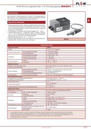
Electronic Flow Meter FC01-Ex-CA (compressed air/gas)<br />
Technical data<br />
1<br />
Flow Meter FC01-Ex-CA<br />
with CST-Ex<br />
calorimetric monitoring head<br />
General data<br />
Media<br />
air (other media upon request)<br />
Measuring function<br />
flow rate / volume flow<br />
mass flow / temperature<br />
Display<br />
2 x 16-digit LCD-display<br />
Parameter assignment, calibration by:<br />
keypads<br />
Temperature range (electronic control unit in circulating air)<br />
+10 °C...+43 °C (ambient temperature)<br />
Electrical data<br />
Input voltage DC 24 V (19...32 V)<br />
Current consumption (V V = 24 V DC)<br />
170 mA / 200 mA*)<br />
Analogue output (flow and/or temperature)<br />
0/4-20 mA or 0/2-10 V or 0/1-5 V<br />
Signal outputs 2 relay outputs (2 limit values) 2 change-over contacts AC/DC 50 V / 1 A / 50 W<br />
4 transistor outputs (2 limit values + 2 status) open collector outputs DC 36 V/150 mA/1.5 W<br />
Flow measurement<br />
Measuring range<br />
(display range) air 0.7...50 Nm/s (0.0...75 Nm/s), see table next page<br />
(related to velocity available at sensor) air < ± 5 % of final value MW (higher accuracy on request)<br />
Accuracy (4)<br />
Repeatability (1) air < 1 % of measured value<br />
Temperature drift<br />
(electronic control unit) air 0.1 %/°K/of final value<br />
Response delay air (2) 3 s<br />
Temperature measuring range -40 °C...+75 °C<br />
measurement accuracy ± 1.5 % of final value<br />
Mechanical data (surface-mounted housing)<br />
Degree of protection<br />
Materials<br />
Housing dimensions (LxWxH)<br />
Mass<br />
IP54<br />
polycarbonate<br />
240 x 120 x 90 mm<br />
1750 g<br />
Cables voltage supply 3 x 0.75 mm 2 (AWG 18)<br />
to monitoring head<br />
LiYCY 4 x 2 x 0.75 mm 2 (AWG 18), light blue<br />
analogue output 2 x LifYCY 2 x 0.25 mm 2 (AWG 24)<br />
signal outputs LifYCY 4 x 2 x 0.2 mm 2 (AWG 24)<br />
equipotential bonding ≥ 1.5 mm 2 (H07V-k 1.5 mm 2 ) (AWG 26)<br />
Max. cable length to monitoring head for safety reasons limited to 200 m 3)<br />
* With output C2, the current consumption may be up to 230 mA ± 10 %.<br />
(1) at constant temperature and flow conditions, and stable thermal conductivity<br />
(2) Delay with the switch point set to 10 m/s and the flow at 20 m/s, after a sudden complete stop.<br />
(3) Mind the equipotential bonding, shield resistance max. 1 Ω (see connection diagram)<br />
(4) The accuracy values were determined under ideal conditions:<br />
- symmetrical complete flow profile<br />
- correct mounting in the pipe<br />
- inlets and outlets according to EN ISO 5167-1<br />
1 - 128<br />
www.e-t-a.com Issue A (270308)
8<br />
8<br />
8<br />
8<br />
Electronic Flow Meter FC01-Ex-CA (compressed air/gas)<br />
Block diagram<br />
Flow measurement range (refering to the medium air)<br />
Sensor<br />
interface<br />
Calorimetric<br />
monitoring<br />
head<br />
Input voltage:<br />
Keyboard/display:<br />
User interface 1:<br />
User interface 2:<br />
Controller system:<br />
Sensor interface:<br />
Power supply DC<br />
Micro controller<br />
system<br />
Keyboard and display<br />
DC 19…32 V<br />
User<br />
interface 1<br />
User<br />
interface 2<br />
keypads<br />
LC display<br />
2 x 16 digits<br />
relay outputs: 2 limit values<br />
transistor outputs: 2 limit values +<br />
1 error indication +<br />
1 busy or quantity-related<br />
pulse output<br />
(software selected)<br />
analogue outputs<br />
current or voltage<br />
signal processing<br />
I/O - controlling<br />
monitoring<br />
parameter memory<br />
calorimetric monitoring head<br />
The flow measurement range is determined by the inner pipe<br />
diameter (see table). It can be calculated with the following equation:<br />
Q = V N x A R<br />
Q (Nm 3 /h - flow quantity<br />
V N (m/h - average standard velocity<br />
A R (m 2 ) - pipe cross section<br />
inner pipe diameter measuring range display range<br />
D in mm in Nm 3 /h in Nm 3 /h<br />
20 57 84<br />
30 127 190<br />
40 226 339<br />
50 353 530<br />
60 509 763<br />
70 693 1039<br />
80 905 1357<br />
90 1145 1717<br />
100 1414 2120<br />
150 3180 4771<br />
200 5655 8482<br />
250 8836 13253<br />
Setting range for internal pipe diameter: 10.0 mm...999.9 mm<br />
Velocity range:<br />
0...50 Nm/s (75 Nm/s)<br />
Accuracy: ±5 % of measured value/±0.5 % of final value<br />
Reproducibility: ±1 % of measured value/ ±0.5 % of final value<br />
(5 % final value - 100 % final value)<br />
Temperature drift: ±0.1 %/K/final value<br />
1<br />
Connection diagram FC01-Ex-CA for relay and analogue outputs V1, V2, C1<br />
LiYCY 4x2x0,75 mm 2<br />
SGND<br />
R(Tdiff)-LO<br />
R(Tdiff)-HI<br />
IS<br />
AGND<br />
R(Tref)-LO<br />
R(Tref)-HI<br />
R(HEIZ)-HI<br />
R(HEIZ)-LO<br />
black<br />
pin k<br />
gray<br />
red<br />
blue<br />
white<br />
brown<br />
green<br />
yellow<br />
* recommended<br />
** E/ -emitter terminal<br />
C/ -collector terminal<br />
*** identical with 9002/77-093-040-001<br />
# SGNDA1<br />
SGNDA2 }ungrounded<br />
Apply shield on one side only.<br />
3<br />
4<br />
9002/22-032-300-111<br />
4 3<br />
2 1<br />
3<br />
4<br />
/PA<br />
USLKG 5<br />
8x0.14 mm 2 single conductor<br />
black: 0.5 mm 2<br />
9002/22-093-040-001 ***<br />
9002/22-093-040-001 ***<br />
1<br />
2<br />
1<br />
2<br />
9002/13-199-225-001<br />
4 3<br />
2 1<br />
AC/DC 24 V<br />
AC/DC 24 V<br />
pink<br />
grey<br />
red<br />
blue<br />
white<br />
black<br />
brown<br />
green<br />
yellow<br />
blue<br />
brown<br />
yellow/green<br />
0.5 mm 2<br />
1 2 3 4 5 6 7 9 10 1 2 3 1 2 3 4<br />
3<br />
2<br />
1<br />
XV XSK XTF<br />
M<br />
equipotential bonding system<br />
XAS XAO XAH<br />
1 2 3 4 5 6 7<br />
1 2 3 4 5 6 7<br />
1 2 3 4 5 6 7<br />
/LIM2<br />
LIM2COM<br />
LIM2<br />
SGNDL2<br />
/LIM1<br />
LIM1COM<br />
LIM1<br />
SGNDL1<br />
ANA2GND<br />
ANAO2<br />
SGNDA2 #<br />
SGNDA1 #<br />
ANA1GND<br />
ANAO1<br />
**<br />
LiYCY 3x0.38 mm 2 *<br />
LiYCY 3x0.38 mm 2 *<br />
LiYCY 2x0.25 mm 2 *<br />
LiYCY 2x0.25 mm 2 *<br />
Analogue outputs:<br />
V1<br />
V2<br />
C1<br />
2x0.75 mm 2 *<br />
≥1.5 mm 2<br />
equipotential bonding monitoring head CST-Ex<br />
1.5 mm 2 - 4 mm 2<br />
Issue A(270308) www.e-t-a.com<br />
1 - 129
8<br />
8<br />
8<br />
8<br />
8<br />
8<br />
8<br />
8<br />
8<br />
Electronic Flow Meter FC01-Ex-CA (compressed air/gas)<br />
Connection diagram FC01-Ex-CA for transistor and analogue outputs V1, V2, C1<br />
LIM1<br />
**<br />
C/ +<br />
1<br />
LiYCY 4x2x0.75 mm 2<br />
SGND<br />
R(Tdiff)-LO<br />
R(Tdiff)-HI<br />
IS<br />
AGND<br />
R(Tref)-LO<br />
R(Tref)-HI<br />
R(HEIZ)-HI<br />
R(HEIZ)-LO<br />
black<br />
pink<br />
grey<br />
red<br />
blue<br />
white<br />
brown<br />
green<br />
yellow<br />
* recommended<br />
** E/ -emitter terminal<br />
C/ -collector terminal<br />
*** identical with 9002/77-093-040-001<br />
# SGNDA1<br />
SGNDA2}ungrounded<br />
Apply shield on one side only.<br />
yellow<br />
3<br />
4<br />
3<br />
4<br />
/PA<br />
8x0.14 mm 2 single conductor<br />
black: 0.5 mm 2<br />
9002/22-093-040-001 ***<br />
1<br />
2<br />
9002/22-032-300-111<br />
4 3<br />
2 1<br />
9002/22-093-040-001 ***<br />
USLKG 5<br />
1<br />
2<br />
9002/13-199-225-001<br />
4 3<br />
2 1<br />
AC/DC 24 V<br />
AC/DC 24 V<br />
pink<br />
grey<br />
red<br />
blue<br />
white<br />
black<br />
brown<br />
green<br />
yellow<br />
blue<br />
brown<br />
yellow/green<br />
0.5 mm 2<br />
1 2 3 4 5 6 7 9 10 1 2 3 1 2 3 4<br />
3<br />
2<br />
1<br />
XV XSK XTF<br />
M<br />
equipotential bonding system<br />
XAS XAO XAH<br />
1 2 3 4 5 6 7<br />
1 2 3 4 5 6 7<br />
1 2 3 4 5 6 7<br />
LIM1 E/ -<br />
LIM2 C/ +<br />
LIM2 E/ -<br />
BUSY/PULSE C/+<br />
BUSY/PULSE E/ -<br />
ERROR C/ +<br />
ERROR E/ -<br />
ANA2GND<br />
ANAO2<br />
SGNDA2 #<br />
SGNDA1 #<br />
ANA1GND<br />
ANAO1<br />
SGND<br />
LifYCY 4x2x0.2 mm 2<br />
LiYCY 2x0.25 mm 2 *<br />
LiYCY 2x0.25 mm 2 *<br />
Analogue outputs:<br />
V1<br />
V2<br />
C1<br />
2x0.75 mm 2 *<br />
≥1.5 mm 2<br />
equipotential bonding monitoring head CST-Ex<br />
1.5 mm 2 - 4 mm 2<br />
Connection diagram recommended connection of pulse output<br />
Electronic signal processing<br />
Electromagnetic pulse counter<br />
XAS XAO XAH<br />
XAS XAO XAH<br />
1<br />
2<br />
3<br />
4<br />
5<br />
6<br />
7<br />
1<br />
2<br />
3<br />
4<br />
5<br />
6<br />
7<br />
1<br />
2<br />
3<br />
4<br />
5<br />
6<br />
7<br />
1<br />
2<br />
3<br />
4<br />
5<br />
6<br />
7<br />
1<br />
2<br />
3<br />
4<br />
5<br />
6<br />
7<br />
1<br />
2<br />
3<br />
4<br />
5<br />
6<br />
7<br />
8<br />
Zener voltage<br />
i C<br />
t L t ON t<br />
U C<br />
U V<br />
i L ≤ 10 mA<br />
U V<br />
U C<br />
i C<br />
U V
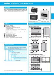
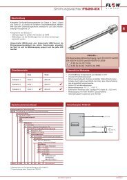
FC01-Ex-CA - Monitoring Head CST-Ex<br />
Description<br />
Thread-mounted calorimetric monitoring head<br />
Thread-mounted Ex approved calorimetric monitoring head for Flow<br />
Meter FC01-Ex-CA. For use in hazardous areas in equipment group II,<br />
category 1 (zones 0 and 20).<br />
Features<br />
● Medium temperature -40 °C...+75 °C<br />
● material monitoring head:<br />
- stainless steel 1.4571<br />
- Hastelloy C4 2.4610<br />
- Titanium G7 3.7235<br />
● EC type test certificate to EN 50014, EN 50020, EN 50281-1-1,<br />
EN 50284 and EN 1127-1 type of protection II 1/2 GD T 130<br />
°C IP67 EEx ia IIC T4.<br />
CST-Ex-..<br />
with Ex approval<br />
1<br />
Ordering information<br />
Type No.<br />
CST-Ex<br />
Thread-mounted monitoring head with calorimetric sensors<br />
Process connection<br />
11 thread size G1/2A<br />
Medium<br />
A air<br />
S other media (please enquire)<br />
Material of areas exposed to medium<br />
M1 stainless steel 1.4571 (standard)<br />
M2 Hastelloy C4 2.4610<br />
M6 Titanium G7 3.7235<br />
Length of shank/thread<br />
L08 27.5 mm (standard)<br />
L10 36 mm<br />
Electrical connection<br />
E20 round connector<br />
with gold-plated contacts<br />
Certification<br />
T5 approval to EC directive<br />
94/9/EG (ATEX 100 a)*)<br />
Specification of medium<br />
xxx<br />
CST-Ex - 11 W M1 L08 E20 T5 - ... ordering example<br />
*) for detailed information please see section 0.<br />
Technical data<br />
Type of head<br />
Thread/rated dia.<br />
Length of shank<br />
Length of sensor<br />
Suitable for pipe diameter<br />
Suitable for media<br />
Temperature range -40...+75 °C<br />
(medium + monitoring head zone T1)<br />
Temperature range -30...+75 °C<br />
(monitoring head zone T 2 )<br />
Pressure resistance (1)<br />
thread-mounted<br />
G1/2A<br />
27.5 mm, 36 mm<br />
14 mm<br />
DN 20...DN 50 (...L08...)<br />
DN 20...DN250 (...L10...)<br />
gases, depending on the resistance<br />
of material and Ex approval (ignitable<br />
media: see Ex approval)<br />
100 bar/1470 PSI<br />
Degree of protection (connector) (2) IP67<br />
Material<br />
stainless steel 1.4571/AISI 316 Ti<br />
Hastelloy C4 2.4610<br />
Connector<br />
copper tin (CuZn)<br />
Cable to electronic control unit LiYCY 4 x 2 x 0.75 mm 2 (AWG 18),<br />
light blue<br />
(1) Admissible operating pressure to DIN 2401, measured at max. temperature (= max.<br />
medium temperature).<br />
(2) with mating connector<br />
Dimensions<br />
CST-Ex-11xxxL08xxx<br />
27.5<br />
1.08<br />
G1/2A<br />
14<br />
.551<br />
undercut<br />
DIN 3852/B<br />
SW27<br />
1.06 in.<br />
T 1<br />
80.5 T 2<br />
41.5<br />
3.17<br />
1.63<br />
36<br />
1.42<br />
CST-Ex-11xxxL10xxx<br />
10 14<br />
.394 .551<br />
G1/2A<br />
ø18<br />
.709<br />
undercut<br />
DIN 3852/A<br />
SW27<br />
1.06 in.<br />
T , T - temperature zones<br />
1 2<br />
This is a metric design and millimeter dimensions take precedence ( mm )<br />
inch<br />
Issue A(270308) www.e-t-a.com<br />
1 - 131
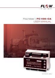
FC01-Ex-CA - Cable type and accessories<br />
Cable type 17 with connectors<br />
Description<br />
Cable between Flow Meter FC01-Ex-CA and calorimetric monitoring<br />
head CST-Ex.<br />
1<br />
● Connection to monitoring head by means of 12-pole<br />
round connector<br />
● Connection to FC01-Ex-CA: wire end ferrules for connection to<br />
ex-barriers<br />
Technical data<br />
Accessories<br />
Cable type 17<br />
Features: paired control line, fully shielded, light-blue insulation,<br />
for intrinsically safe systems, electrical and thermal<br />
properties at +20 °C<br />
Conductor resistance:<br />
< 25 Ω/km<br />
Insulation resistance:<br />
> 200 MΩ/km<br />
Capacity<br />
(wire/wire/grounded shield) 110 pF/m ± 20 %<br />
Operating voltage<br />
(VDE 0812)<br />
max. 500 V AC<br />
Test voltage<br />
(wire/wire/shield)<br />
1200 V AC<br />
Max. load<br />
10 A<br />
Wave impedance<br />
f > 100 kHz / 60...70 Ω<br />
Inductance<br />
wire/wire<br />
0.7 mH/km<br />
wire/shield<br />
0.5 mH/km<br />
Capacitive coupling (800 Hz) 0...1200 pF/100 m<br />
Temperature range:<br />
-10 °C...+80 °C (operation)<br />
-30 °C...+80 °C (transport and storage)<br />
12-pole round connector<br />
(without cable, for individual wiring by customer)<br />
0Z112Z000172<br />
ø25<br />
This is a metric design and millimeter dimensions take precedence ( mm )<br />
inch<br />
Caution: Standard warranty cover will be invalidated if the correct<br />
E-T-A monitoring head/control unit connecting cable is not<br />
used.<br />
51<br />
Ordering information<br />
Type between calorimetric monitoring heads CST-Ex and FC01-Ex-<br />
CA<br />
Do + Ka type 17 PVC-insulated cable, type LifYCY 4x2x0.75mm 2 (AWG 18)<br />
12-pole round connector + wire end ferrules<br />
Available cable lengths<br />
...m 2 m, 3 m, 5 m, 8 m, 10 m, 15 m, 20 m, 25 m,<br />
30 m, 40 m, 50 m, 60 m, 70 m, 80 m, 90 m<br />
100...200 m (in 10 m steps) upon request<br />
(longer lead times)<br />
Do + Ka type 17 - 2 m<br />
ordering example<br />
1 - 132<br />
www.e-t-a.com Issue A (270308)
FC01-Ex-CA - Certificate<br />
PTB ATEX Test Certificate<br />
1<br />
Issue A(270308) www.e-t-a.com<br />
1 - 133
FC01-Ex - Certificate<br />
EC type test certificate FC01-Ex-CA<br />
1<br />
1 - 134<br />
www.e-t-a.com<br />
Issue A (270308)
FC01-Ex - Certificate<br />
EC type test certificate FC01-Ex-CA<br />
1<br />
Issue A(270308)<br />
www.e-t-a.com<br />
1 - 135
FC01-Ex - Certificate<br />
EG-Declaration of Conformity CST-Ex<br />
1<br />
1 - 136<br />
www.e-t-a.com Issue A (270308)
FC01-Ex-CA - Certificate<br />
EC type test certificate FC01-Ex-CA<br />
1<br />
Issue A(270308) www.e-t-a.com<br />
1 - 137
FC01-Ex-CA - Certificate<br />
EC type test certificate FC01-Ex<br />
1<br />
1 - 138<br />
www.e-t-a.com Issue A (270308)
FC01-Ex-CA - Certificate<br />
EC type test certificate FC01-Ex-CA<br />
1<br />
Issue A(270308) www.e-t-a.com<br />
1 - 139
FC01-Ex - Certificate<br />
EG-Declaration of Conformity FC01-Ex-CA<br />
1<br />
1 - 140<br />
www.e-t-a.com Issue A (270308)