Strömungswächter | SW118 Flow Monitor | SW118 - FlowVision GmbH
Strömungswächter | SW118 Flow Monitor | SW118 - FlowVision GmbH
Strömungswächter | SW118 Flow Monitor | SW118 - FlowVision GmbH
- No tags were found...

Create successful ePaper yourself
Turn your PDF publications into a flip-book with our unique Google optimized e-Paper software.
Strömungswächter | <strong>SW118</strong>Montage- und Einstellanleitung<strong>Flow</strong> <strong>Monitor</strong> | <strong>SW118</strong>Instructions for Installation and AdjustmentM_<strong>SW118</strong>_0210_d_e
GMBHStrömungswächter| <strong>SW118</strong>Diese Anleitung unterstützt Sie beim Einbau,Anschließen und Einstellen des Strömungswächters.Die Garantie erlischt bei unsachgemäßerHandhabung sowie bei Geräte-Demontagen, dienicht in dieser Anleitung beschrieben sind.Für mechanische oder elektrischeBeschädigungen als Folge unsachgemäßerHandhabung sowie deren möglicheFolgeschäden wird keine Haftungübernommen.Please follow these installation, connection andadjustment instructions carefully. Failure to complywith these instructions or misuse of this equipmentwill void your warranty coverage.Equipment installation, connection andadjustment by qualified personnel only!SicherheitshinweisEine Nichtbeachtung der Montage- undBedienungsanleitung kann zu erheblichen Schädenam Gerät und an der Anlage führen. <strong>Flow</strong>Visionübernimmt gegenüber Kunden oder Dritten keineHaftung, Gewährleistung oder Garantie für Mängeloder Schäden, die durch fehlerhaften Einbau oderunsachgemäße Handhabung unter Nichtbeachtungder Montage- und Bedienungsanleitung verursachtsind.ImportantPlease follow these instructions carefully. Failure tocomply, or misuse of this equipment, could resultin serious damage both to the equipment itself andto the installation. <strong>Flow</strong> Vision is unable to acceptresponsibility for customer or third party liability,warranty claims or damage caused by incorrectinstallation or improper handling resulting formnon-observance of these instructions.2
Beschreibung | Description<strong>SW118</strong> | <strong>Flow</strong> <strong>Monitor</strong>GMBH1 BeschreibungDer Strömungswächter wird zur Strö mungs überwachungvon flüssigen oder gasförmigen Medieneingesetzt. Die folgenden Gerätemerkmale steigern dieZuver lässigkeit und erhöhen die Betriebssicherheit:• Die Überwachung erfolgt - ohne mechanisch bewegteTeile - nach dem kalorimetrischen Prinzip.• Der gewünschte MIN- oder MAX-Schaltpunkt iststufenlos einstellbar und wird mittels Duo-LED(rot/grün) signalisiert.• Mit einem Schalter kann die Mediumsart (Wasser,Öl, Luft) gewählt werden.• Mit einstellbaren Verzögerungen: 60 s Einschaltverzögerung oder 10 s Umschaltverzögerung.1 DescriptionThis <strong>Flow</strong> <strong>Monitor</strong> is designed to monitor the flowof liquids and gases. Important operational safetyand reliability enhancing features designed andbuilt into these units include:• Calorimetric flow monitoring, which avoids theneed for moving parts in the flow.• The desired MIN or MAX switch point is steplesslyadjustable and is clearly indi cated by dualcolour LED (red/green).• Medium selector switch with three settings (water,oil, air).• With either no delay, or with a 60 s switch-ondelay or 10 s change over delay.3
GMBHStrömungswächter| <strong>SW118</strong>Technische Daten | technical data2 Technische DatenÜberwachungsbereich Strömung:flüssige Mediengasförmige MedienZulässiger Temperaturbereich:min. 10 mm/smax. 4 m/smin. 0,5 m/smax. 50 m/sdes Mediums -25 °C … +70 °Cder Auswerteelektronik -25 °C … +50 °CDruckfestigkeit Messkopf:Ansprechzeit:100 bar/1450 psiWasser ca. 2 s *Öl ca. 4 s *Luft ca. 7 s ** Verzögerungswerte gemessen bei Schaltpunkteinstellung auf 1 m/s und einer Be triebs -strömung von 2 m/s nach plötzlichem Strömungsstillstand.Schutzart:Messkopf IP 67Auswerteelektronik IP 65Nennspannung:AC 230 V (+10%/-15%)AC 115 V (+10%/-15%)AC 24 V (+10%/-15%)DC 24 V ±10%2 Technical Data<strong>Flow</strong> rate range:liquidsgasesTemperature range:10 mm/s (0.39 inch/s) minimum4 m/s (13.1 ft./s) maximum0.5 m/s (20 inch/s) minimum50 m/s (164 ft./s) maximumof the medium -25 °C … +70 °C(-13 °F to +158 °F)of the control unit -25 °C … +50 °C(-13 °F to +122 °F)Pressure resistance of the monitoring head:100 bar/1450 psiResponse delay:water approx. 2 s *oil approx. 4 s *air approx. 7 s ** Delay with the switch point set to 1 m/s (3.3ft./s) and the flow rate at 2 m/s (6.6 ft./s),after a sudden complete flow stoppage.Degree of protection:<strong>Monitor</strong>ing head IP 67Control unit IP 65Input voltage:AC 230 V (+10%/-15%)AC 115 V (+10%/-15%)AC 24 V (+10%/-15%)DC 24 V ±10%4
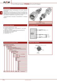
montieren | Installation<strong>SW118</strong> | <strong>Flow</strong> <strong>Monitor</strong>GMBH3 Strömungswächter montieren1 Überprüfen, ob der einzubauende Strö mungswächterfür das Strömungsmedium und dievorhandene Betriebsspannung ausge legt ist.2 Den Einbauort des Strömungswächters wie folgtwählen (siehe Fig. 1):a Um Strömungsturbulenzen an den Mess -fühlern zu vermeiden, den Mess kopf nurin gerade Rohrleitungen einbauen. Aufaus reichenden Abstand zu Quer schnitts -ände run gen und Rohr krüm mun gen achten.Minimal erforderliche Einlauflänge 10 x Dund Auslauflänge 5 x D (nach DIN 1952).(D = Rohrnennweite)3 <strong>Monitor</strong>ing head installation1 Check that the flow monitor is suitable for themedium to be monitored and for the availablesupply voltage.2 For best performance the monitoring head shouldbe installed in the pipeline in accordance with thefollowing conditions (see fig. 1):a The monitoring head should be installedonly in a straight section of piping. Thereshould be a distance of at least 10 pipediameters before the monitoring head and5 pipe diameters after the monitoring headbefore or after any bends and changes inpipe diameter, to avoid any effects of turbulence.Bei senkrechter Leitung: Bei waagerechter Leitung: Die Messfühler müssen neben-Nur in Steigleitungen einbauen. Nur von unten einbauen. einander im Rohr liegen.Vertical pipelines: Horizontal pipelines : The two sensors (S) must beMedium should be rising. <strong>Monitor</strong>ing head should be side by side across themounted on the underside. direction of flow.SFCSSFCFCFCFig. 15
GMBHStrömungswächter| <strong>SW118</strong>montieren | InstallationbcdHinweis:Bei senkrechter Leitung möglichst nurin Steigleitungen einbauen, um falscheSignale durch Luftpolsterbildung zu vermeiden.Bei waagerechter Leitung Strömungswächtervon unten einbauen.Um evtl. Funktionsstörungen auszuschließensind energiereiche induktive,kapazitive und hochfrequente Einstreuungenzu vermeiden.Bei Gasen ist die Einbaulage bei senkrechterund waagerechter Leitung beliebig.3 Messkopf mit Rohrfitting vergleichen undüberprüfen, ob die beiden Messfühler (S) imeingebauten Zustand im Strömungsmediumliegen (siehe Fig. 1), ohne den Rohr leitungsquerschnittwesentlich zu verringern.bcdNote:In the case of vertical pipelines the monitoringhead should be installed where theflow is rising, if possible.For horizontal pipelines the monitoringhead should be mounted on the undersideof the line (suspended).Avoid installing the monitoring head inknown areas of high electrical inductance,capacitance, or high-frequency electromagneticfields.If gases are the medium to be monitored,the mounting attitude of the monitoring headis unimportant in either vertical or horizontalpipelines.3 The monitoring head should be screwed intothe pipeline far enough to ensure that the sensors(S) are positioned fully in the flow (seefig. 1). However, care should also be takenthat the monitoring head is not screwed in toofar, thus causing an undue restriction in thepipe bore.ACHTUNG!• Mit einem Gabelschlüssel (SW 27) an denSchlüsselansatzflächen (FC) (siehe Fig. 1) hinterdem Gehäuse und nicht mit dem Gehäusefestziehen!• Strömungswächter mit entsprechendem Dichtungsmaterialin das vorgesehene Rohr fittingeinschrauben.• Die beiden Messfühler (S) müssen nebeneinanderim Strömungsmedium liegen. Dies ist der Fall,wenn die Schlüsselansatz flächen (FC) parallelzur Rohrleitung stehen (siehe Fig. 1).• Beim Anziehen des Messkopfes die VDI Richtlinien2230 für das Anzugsmoment un bedingt beachten.CAUTION!• When tightening the flow monitor please use theflats provided (SW 27) (FC) and do not turn orapply torque to the housing (see fig. 1).• It is important that thread sealing compound ormaterial of the correct type for the media is usedwhen fitting the monitoring head.• The two sensors (S) on the monitoring head mustbe aligned side by side directly across the directionof flow. The sensors are cor rectly positionedwhen the wrench flats (FC) are aligned parallelwith the pipeline (see fig. 1).• Do not overtighten.6
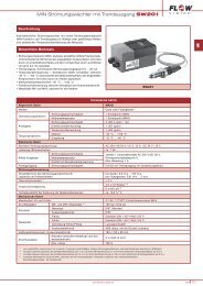
AnschlieSSen | Electrical connection<strong>SW118</strong> | <strong>Flow</strong> <strong>Monitor</strong>GMBH4 AnschließenACHTUNG!• Überprüfen, ob die Versorgungsspannungmit der Nennspannung des Strömungs wäch -ters übereinstimmt.1 Gehäusedeckel abschrauben und entfernen.2 Kabel für Netzanschluss und Relaisausgangdurch die Kabelverschraubung führen.3 Den Netzanschluss an den Klemmen 1 und2 und den Relaisausgang an den Klemmen3 … 5 anschließen (siehe Fig. 2).4 Kabelverschraubung zur Zugentlastung derKabel handfest anziehen.5 Versorgungsspannung anschließen.4 Electrical connectionCAUTION!• Check that the supply voltage correspondswith the voltage rating shown on the system.1 Loosen the retaining screws and remove thecover of the housing.2 Feed the supply input cable and relay connectingcable through the appropriate cablegland.3 Connect the supply input cable to terminals1 and 2, and the relay connecting cable toterminals 3 … 5 (see fig. 2).4 Tighten the cable gland fingertight.5 Connect power supply.MIN oder/or MAXRelais unerregt dargestellt (LED rot)relay shown de-energized (LED red)1 2 3 4 5AC: L NDC: + -Netzanschlussmains0 IRelaisausgängerelay outputs0 = Überwachungsmedium ist im unzulässigen Bereichmedium to be monitored is in the inadmissible rangeI = Überwachungsmedium ist im zulässigen Bereichmedium to be monitored is in the operating rangeFig. 27
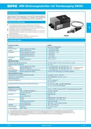
GMBHStrömungswächter| <strong>SW118</strong>Einstellen5 Ansprechwert Strömung einstellenVoraussetzung:Der Strömungswächter ist entsprechend den Kapiteln3 und 4 montiert und angeschlossen.Auslieferungszustand:MIN-Funktion eingestellt für Wasser, ohne Verzögerung.1 In der zu überwachenden Rohrleitung ist diekritische Strömung mit zugehöriger Tempe raturherzustellen, bei welcher der Strö mungs wächteransprechen soll. Die Aufheizzeit des Messkopfesbeträgt bei flüssigen Medien ca. 5 Minuten undbei gasförmigen Medien ca. 15 Minuten.ACHTUNG!• Auf gleichbleibende Strö mungs bedingungenachten. In flüssigen Medien ist Blasenbildungzu vermeiden.2 Mediumschalter (MS) dem zu überwachen denMedium anpassen (siehe Fig. 3):Pos. I =Pos. II =Pos. III =Wasser oder Flüssigkeiten mitähnlicher WärmeleitungÖl oder Flüssigkeiten mit ähnlicherWärmeleitungLuft oder Gase mit ähnlicherWärmeleitung3 MIN- oder MAX-Funktion mit Funktions schalter(FS) wählen (siehe Fig. 3).4 Um den Ansprechwert Strömung leichter einstellenzu können, Verzögerungsschalter (V1 und V2) imAuslieferungszustand lassen (ohne Verzögerung:V1 geschlossen, V2 offen) (siehe Fig. 3).5 Die Duo-LED-Anzeige auf der Auswerte elektronikzeigt die Position des Strömungs schaltpunktes an.Bei MIN-Schaltpunkt:GRÜN =Die Strömung ist über demeingestellten Schaltpunkt.ROT = Die Strömung ist unter demeingestellten Schaltpunkt.Bei MAX-Schaltpunkt:GRÜN =Die Strömung ist unter demeingestellten Schaltpunkt.ROT = Die Strömung ist über demeingestellten Schaltpunkt.5 Adjustment of flow response valueRequirement:Ensure flow monitor has been correctly installed andconnected in accordance with chapters 3 and 4. Readthe entire section including notes before startingadjustment.Condition as delivered:MIN-function factory preset to water, with nodelay.1 Start by bringing the system to the critical flow rateat which the flow monitor should respond and to itsnormal operating tempe rature and allow it to reachthermal stabilization. This takes at least 5 minutes forliquids and 15 minutes for gases.CAUTION!• Care should be taken to ensure that the flow iscontinuous and for liquids free of bubbles (doesn’tapply when monitoring foam).2 Set medium selector switch (MS) to (see fig. 3):position I = for water or media with similarthermal conductivitiesposition II = for oil or media with similarthermal conductivitiesposition III = for air or gases with similarthermal conductivities3 Select either the MIN or MAX function by meansof selector switch (FS) (see fig. 3).4 To facilitate flow response setting leave the delayswitches (V1 and V2) in the condition as delivered(no delay: V1 closed, V2 open) (see fig. 3).5 The dual colour LED on the control unit indicatesthe position of the flow switch point.With MIN function selected:GREEN = flow rate is at or above the setresponse value.RED= flow rate is below the setresponse value.With MAX function selected:GREEN = flow rate is at or below the setresponse value.RED= flow rate is above the setresponse value.8
<strong>SW118</strong> | <strong>Flow</strong> <strong>Monitor</strong>AdjustmentGMBH6 Mit dem Potentiometer (R) den Schaltpunkt aufden Wechselpunkt zwischen GRÜN und ROTeinstellen (siehe Fig. 3):MIN-Schaltpunkt:• von GRÜN nach ROT:im Uhrzeigersinn• von ROT nach GRÜN:gegen den Uhrzeigersinn.MAX-Schaltpunkt:• von GRÜN nach ROT:gegen den Uhrzeigersinn• von ROT nach GRÜN:im Uhrzeigersinn.Um sicherzugehen, Schaltpunkt mehrmals an -steu ern.ACHTUNG!• Ist in Pos. II oder III kein Schaltpunkt einstellbar,Mediumschalter (MS) in die nächstniedrigerePosition umschalten.7 Falls notwendig, einstellbare Verzögerung mitSchalter V1 (Einschaltverzögerung) und V2(Umschaltverzögerung) von grün nach rot wählen.8 Gehäusedeckel aufsetzen und Befesti gungsschraubenanziehen.6 To adjust the switching point, turn the flow adjustmentpotentiometer screw (R) to the exact pointthe LED changes (see Fig. 3):MIN-function:• from GREEN to RED- turn the screw clockwise• from RED to GREEN- turn the screw counterclockwiseMAX-function:• from GREEN to RED- turn the screw counterclockwise• from RED to GREEN- turn the screw clockwise.Repeat this procedure several times to ensurecorrect adjustment.CAUTION!• If the switch point cannot be set when the mediumselector switch (MS) is in position II or III, the switchshould be set to the next lower position.7 If required, select the desired delay from green tored by means of switch V1 for switch-on delay orswitch V2 for change over delay.8 Replace cover and tighten the retainingscrews.FSMIN MAXV1 V2 Verzögerungsschalter V1, V2Delay switches V1, V21 2 3 4 5IIIIIIMSLEDMIN/MAXRV1 V2V1 V2V1 V2ohne Verzögerung(Auslieferungszustand)with no delay(condition as delivered)Einschaltverzögerung 60 swith a 60 s switch-on delayUmschaltverzögerung 10 swith a 10 s change over delaySchutzschalterCircuit breaker Fig. 39
GMBHStrömungswächter| <strong>SW118</strong>Wartung | Maintenance6 WartungDer Strömungswächter ist wartungsfrei bei Medien,die sich nicht an den Messfühlern festsetzen.• Die Messfühler in entsprechenden Erfahrungsintervallenvon Ablagerungen reinigen.• Hierbei mechanische Verletzungen der Mess fühlervermeiden.Die Erfahrungsintervalle werden durch periodischePrüfungen der Fühler festgesetzt.6 Maintenance<strong>Flow</strong>Vision <strong>Flow</strong> <strong>Monitor</strong>s are virtually maintenancefree. However:• The monitoring head sensors must be kept freeof deposits.• Avoid damaging the sensors during cleaning.When first installed the monitoring head should bechecked periodically to see if cleaning is requireduntil an operating pattern is established.10
Störungen | Difficulties<strong>SW118</strong> | <strong>Flow</strong> <strong>Monitor</strong>GMBH7 Störungen beseitigenStörung:Ungewolltes Ansprechen des Schalt punktes.Beseitigung:• Bei flüssigen Medien Blasenbildung vermeiden.• Schaltpunkt auf größeren Abstand zurNormalströmung legen, besonders bei größerenTemperaturschwankungen.• Überprüfen, ob der Strömungswächterent sprechend den Angaben in Kapitel 3„Strömungswächter montieren“ eingebaut ist.• Strömungswächter ausbauen und Messfühlerreinigen.7 Operating difficultiesProblem:Solution:Incorrect switching• Avoid bubbles in the medium.• Adjust the switch point to permit a greaterdifferential from the normal flow rate, particularlyin the event of a wide temperature rangein the medium.• Ensure monitoring head has been correctlyinstalled in accordance with chapter 3.• Remove the monitoring head and clean thesensors.Störung:Schaltpunkt nicht einstellbar.Beseitigung:• Position des Mediumschalters (MS) überprüfen.Problem:Solution:Switch point cannot be adjusted.• Verify position of the medium selector switch(MS).Störung:Keine LED leuchtet.Beseitigung:• Spannungsversorgung prüfen. Bei 24 VVersorgungsspannung: Internen Schutzschalterprüfen, ggf. wieder einschalten.Problem:Solution:no LED lighted.• check power supply. At 24 V supply voltage:check internal circuit breakers, resetif applicable.11
<strong>Flow</strong>Vision <strong>GmbH</strong>Im Erlet 690518 AltdorfTelefon 0049 (9187) 9 22 93 - 0Telefax 0049 (9187) 9 22 93 - 29info@flowvision-gmbh.dewww.flowvision-gmbh.de