Strömungswächter | SW118 Flow Monitor | SW118 - FlowVision GmbH
Strömungswächter | SW118 Flow Monitor | SW118 - FlowVision GmbH
Strömungswächter | SW118 Flow Monitor | SW118 - FlowVision GmbH
- No tags were found...

You also want an ePaper? Increase the reach of your titles
YUMPU automatically turns print PDFs into web optimized ePapers that Google loves.
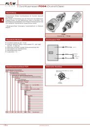
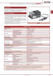
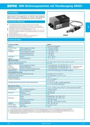
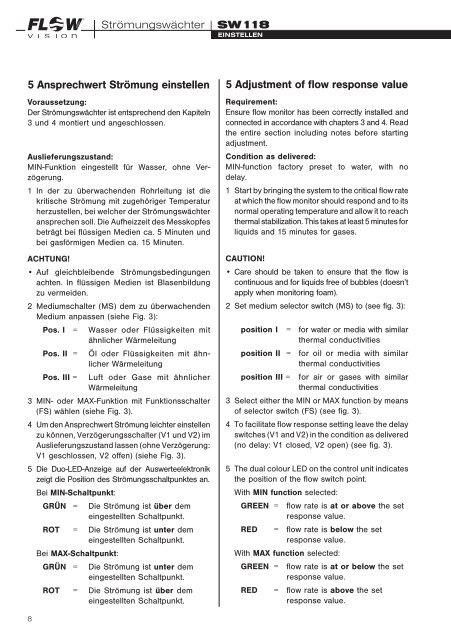
GMBHStrömungswächter| <strong>SW118</strong>Einstellen5 Ansprechwert Strömung einstellenVoraussetzung:Der Strömungswächter ist entsprechend den Kapiteln3 und 4 montiert und angeschlossen.Auslieferungszustand:MIN-Funktion eingestellt für Wasser, ohne Verzögerung.1 In der zu überwachenden Rohrleitung ist diekritische Strömung mit zugehöriger Tempe raturherzustellen, bei welcher der Strö mungs wächteransprechen soll. Die Aufheizzeit des Messkopfesbeträgt bei flüssigen Medien ca. 5 Minuten undbei gasförmigen Medien ca. 15 Minuten.ACHTUNG!• Auf gleichbleibende Strö mungs bedingungenachten. In flüssigen Medien ist Blasenbildungzu vermeiden.2 Mediumschalter (MS) dem zu überwachen denMedium anpassen (siehe Fig. 3):Pos. I =Pos. II =Pos. III =Wasser oder Flüssigkeiten mitähnlicher WärmeleitungÖl oder Flüssigkeiten mit ähnlicherWärmeleitungLuft oder Gase mit ähnlicherWärmeleitung3 MIN- oder MAX-Funktion mit Funktions schalter(FS) wählen (siehe Fig. 3).4 Um den Ansprechwert Strömung leichter einstellenzu können, Verzögerungsschalter (V1 und V2) imAuslieferungszustand lassen (ohne Verzögerung:V1 geschlossen, V2 offen) (siehe Fig. 3).5 Die Duo-LED-Anzeige auf der Auswerte elektronikzeigt die Position des Strömungs schaltpunktes an.Bei MIN-Schaltpunkt:GRÜN =Die Strömung ist über demeingestellten Schaltpunkt.ROT = Die Strömung ist unter demeingestellten Schaltpunkt.Bei MAX-Schaltpunkt:GRÜN =Die Strömung ist unter demeingestellten Schaltpunkt.ROT = Die Strömung ist über demeingestellten Schaltpunkt.5 Adjustment of flow response valueRequirement:Ensure flow monitor has been correctly installed andconnected in accordance with chapters 3 and 4. Readthe entire section including notes before startingadjustment.Condition as delivered:MIN-function factory preset to water, with nodelay.1 Start by bringing the system to the critical flow rateat which the flow monitor should respond and to itsnormal operating tempe rature and allow it to reachthermal stabilization. This takes at least 5 minutes forliquids and 15 minutes for gases.CAUTION!• Care should be taken to ensure that the flow iscontinuous and for liquids free of bubbles (doesn’tapply when monitoring foam).2 Set medium selector switch (MS) to (see fig. 3):position I = for water or media with similarthermal conductivitiesposition II = for oil or media with similarthermal conductivitiesposition III = for air or gases with similarthermal conductivities3 Select either the MIN or MAX function by meansof selector switch (FS) (see fig. 3).4 To facilitate flow response setting leave the delayswitches (V1 and V2) in the condition as delivered(no delay: V1 closed, V2 open) (see fig. 3).5 The dual colour LED on the control unit indicatesthe position of the flow switch point.With MIN function selected:GREEN = flow rate is at or above the setresponse value.RED= flow rate is below the setresponse value.With MAX function selected:GREEN = flow rate is at or below the setresponse value.RED= flow rate is above the setresponse value.8