MIXO modular inserts for multipole connectors
MIXO modular inserts for multipole connectors
MIXO modular inserts for multipole connectors

You also want an ePaper? Increase the reach of your titles
YUMPU automatically turns print PDFs into web optimized ePapers that Google loves.
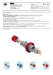
<strong>MIXO</strong> <strong>modular</strong> <strong>inserts</strong> <strong>for</strong> <strong>multipole</strong> <strong>connectors</strong><br />
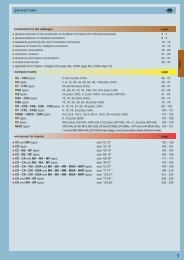
<strong>MIXO</strong> <strong>inserts</strong> <strong>for</strong> <strong>multipole</strong> <strong>connectors</strong> <strong>for</strong> fibre optic and coaxial contacts.<br />
LWL contacts according to CECC 78 001-801 (<strong>for</strong>mer DIN 41 626 part 3) <strong>for</strong> 1 / 2.2 mm POF (Polymer Optical Fibre) and 1.5 / 2.3 MOST<br />
(Media Oriented System Transport) optical fibre.<br />
Coaxial contacts (DIN 41 626) 50 ohm and 75 ohm.<br />
The new <strong>MIXO</strong> insert allows the use of contacts <strong>for</strong> fibre optic and contacts <strong>for</strong> coaxial<br />
cables.<br />
To protect against EMC-problems (electromagnetic interference) and <strong>for</strong> the realization of<br />
galvanic separations on BUS applications of PROFINET/Ethernet fields, solutions with optical<br />
fibres are recommended.<br />
Fibre optic <strong>connectors</strong> are many industrial applications, particularly, modern railway vehicles,<br />
converters, wind energy, naval equipments and robots.<br />
The new <strong>connectors</strong> can be used in applications from -40 °C up to +85°C even in case of<br />
frequent temperature variability.<br />
The <strong>inserts</strong> can be mounted in CX .. TF/TM frames and in the relative enclosures <strong>for</strong> industrial<br />
applications to achieve IP65/66/68/69K degree of protection (according to the required<br />
versions). The realization of mixed <strong>connectors</strong> electrical/optical are also possible.<br />
These new <strong>inserts</strong> keep the same features of our usual <strong>MIXO</strong> series that has an easy<br />
module fixing system.<br />
On request we may provide also POF (Ø 2.2 mm external diameter, Ø 1.0 mm fibre) and<br />
MOST-POF (Ø 2,3 mm external diameter, Ø 1.0 mm fibre) contacts <strong>for</strong> use at higher<br />
temperatures and high temperature variations.<br />
For further optical fibre versions, please contact us.<br />
To assemble the contacts it is needed to cut and strip the cable, to crimp the contact (even<br />
gluing is possible) and then to grind the fibre tip protruding from the contact.<br />
In the same <strong>MIXO</strong> insert it is also possible to use coaxial <strong>connectors</strong> <strong>for</strong> 50 ohm (RG 316/U,<br />
RG 174/U and RG 188 A/U) and 75 ohm (RG 179 B/U, RG 187 A/U and TZC 75 101) cables.<br />
To remove both male and female contacts please use the correct extraction tool.<br />
CECC 78 001-801 contacts<br />
(DIN 41 626, part 3)<br />
Mixo insert<br />
<strong>for</strong> 4 optical fibre contacts<br />
DIN 41 626 contacts<br />
1
<strong>MIXO</strong> <strong>modular</strong> units <strong>for</strong> <strong>multipole</strong> <strong>connectors</strong><br />
Characteristics<br />
<br />
electric contacts in silver-plated or gold-plated brass with<br />
connections to the conductors via crimping.<br />
<br />
pneumatic contacts in plastic with insertion tube connection.<br />
<strong>modular</strong> <strong>inserts</strong> of identical size with insertion system <strong>for</strong><br />
<strong>for</strong>ming the complete module and frame lock tab.<br />
<strong>inserts</strong> in self-extinguishing thermosplastic material, rein<strong>for</strong>ced<br />
with glass fibre, UL 94-V0 approved, with a working<br />
temperature range of -40 °C to +125 °C.<br />
<strong>inserts</strong> in con<strong>for</strong>mance with the requirements of the<br />
EN 61984 standard and certified and marked with the UL,<br />
CSA, CCC, GL marks.<br />
<strong>inserts</strong> with asymmetric guide rails to prevent incorrect<br />
coupling.<br />
position of contacts identified with numbers or codes on both<br />
sides of every insert.<br />
<br />
<br />
<br />
<br />
<br />
<br />
<br />
male/female module carrier frames with mandatory housings<br />
and polarity, in die-cast zinc alloy.<br />
<br />
module lock tab, may be divided according to the number of<br />
modules used; guarantees a perfect stability of the modules<br />
during wiring and coupling/uncoupling of the <strong>connectors</strong>.<br />
asymmetric earth contacts (two <strong>for</strong> frame) with wide contact<br />
surface prevent incorrect coupling; when two or more identical<br />
<strong>connectors</strong> of the <strong>MIXO</strong> series are used, coded pins prevent<br />
incorrect coupling (see Catalogue CN.07).<br />
<br />
<br />
<br />
captive frame fastening screws, with flexible spring washer.<br />
dummy module <strong>for</strong> unused frame slots.<br />
<strong>inserts</strong> contact signal <strong>connectors</strong> and tubes rated rated No. of frame<br />
type type connections current A voltage V slots<br />
CX 01 YF/M main electric crimp 200 1000 2<br />
CX 02 GF/M main electric crimp 100 1000 2<br />
CX 02 4AF/M main electric axial screw 40 1000 1<br />
CX 03 4F/M main electric crimp 40 400/690 1<br />
CX 05 SF/M main electric spring 16 400 1<br />
CX 06 CF/M main electric crimp 16 500 1<br />
CX 08 CF/M main electric crimp 16 400 1<br />
CX 20 CF/M main electric crimp 16 500 2<br />
CX 12 DF/M main / auxiliary electric crimp 10 250 1<br />
CX 17 DF/M main / auxiliary electric crimp 10 160 1<br />
CX 02 HF/M main electric crimp 16 2900/5000 2<br />
CX 02 BF/M multiaxial <strong>connectors</strong> see CX 04 B --- --- --- 2<br />
CX 01 BF/M main / auxiliary + shield electric crimp 10 50 ---<br />
CX 04 BF/M main / auxiliary + shield electric crimp 10 50 ---<br />
CX 03 P pneumatic Ø 1.6 - 3.0 - 4.0 mm gas / liquid ** insertion --- --- 1<br />
CX 02 P pneumatic Ø 6.0 mm gas / liquid ** insertion --- --- 1<br />
CX FM none (dummy module) --- --- --- --- 1<br />
CX 01 JF/M RJ45 + auxiliary electric crimp --- --- 2<br />
CX 02 JF/M RJ45 + auxiliary electric crimp --- --- 3<br />
CX 01 UF/M USB electric --- --- --- 1<br />
CX 04 LF/M POF / MOST / coaxial DIN 41626 optic / electric crimp --- --- 1<br />
** Warning: For obvious reasons of safety, the VDE standard does not permit electric contacts to be present within the same connector group together with contacts <strong>for</strong> the<br />
transmission of liquids. In addition, the use of pneumatic air contacts requires an appropriate filtering and dehydration system to prevent dangerous condensation.<br />
Contacts may be used <strong>for</strong> pressure values of up to a maximum of 8 bar/116 psi.<br />
We remind always to check the correct air flow and/or the electrical/optical conduction in the actual working condition on mated and coupled <strong>connectors</strong>.<br />
2
<strong>MIXO</strong> <strong>modular</strong> units <strong>for</strong> POF and MOST contacts DIN 41626<br />
the <strong>modular</strong> <strong>inserts</strong> must be installed in suitable<br />
frames which are then mounted in traditional<br />
housings or COB panel support<br />
frames <strong>for</strong> <strong>modular</strong> units .......... page: 151**<br />
<strong>modular</strong> units,<br />
crimp connections<br />
POF / MOST crimp contacts<br />
- to crimp contacts CX PLF / PLM and CX MLF / MLM<br />
please use tool CLPZ R<br />
- max external diameter: 2.2 mm (POF)<br />
2.3 mm (MOST)<br />
- polymer fibre diameter: 1.0 mm (POF)<br />
1/1.5 mm (MOST)<br />
- attenuation: < 2.5 dB<br />
- temperature range: -40 °C ÷ +85 °C<br />
** refer to catalogue page CN.07<br />
NEW<br />
description part No. part No.<br />
NEW<br />
without contacts (to be ordered separately)<br />
- female <strong>inserts</strong> <strong>for</strong> female contacts CX 04 LF<br />
- male <strong>inserts</strong> <strong>for</strong> male contacts CX 04 LM<br />
female contacts POF * 1.0 mm<br />
male contacts POF * 1.0 mm<br />
female contacts MOST *** 1/1.5 mm<br />
male contacts MOST *** 1/1.5 mm<br />
CX PLF<br />
CX PLM<br />
CX MLF<br />
CX MLM<br />
* POF = POLYMER OPTICAL FIBRE dimensions in mm dimensions in mm<br />
*** MOST = MEDIA ORIENTED SYSTEM TRANSPORT<br />
CX 04 LF / LM<br />
We recommend to use CLASS enclosures with two<br />
levers or V-Type enclosures (with one or two levers)<br />
that provides a higher coupling depth due to the higher<br />
locking <strong>for</strong>ce they produce. We further suggest the use<br />
of code pins CRF CX / CRM CX.<br />
34 14.7<br />
34.3<br />
M<br />
21.7<br />
10<br />
ø 3<br />
ø 6<br />
M (CX PLM / MLM)<br />
ø 4.6<br />
F<br />
F (CX PLF / MLF)<br />
34<br />
26.2<br />
9.8<br />
ø 6<br />
contacts side (front view)<br />
side with reference arrow ▲<br />
cable stripping <strong>for</strong> fibre optic<br />
min. 12 mm<br />
1<br />
F<br />
1<br />
M<br />
male contact<br />
2<br />
2<br />
3<br />
3<br />
4<br />
4<br />
min. 15 mm<br />
- 1 frame slot<br />
female contact<br />
dimensions shown are not binding<br />
and may be changed without notice<br />
3
tools and accessories <strong>for</strong> crimp contacts<br />
<strong>for</strong> contacts series:<br />
page<br />
CX PLF/PLM .............................................. 3<br />
CX MLF/MLM.............................................. 3<br />
manual crimping tool<br />
polishing disc - polish paper - removal tool<br />
jacket stripper and fibre stripper<br />
cable cutter<br />
description part No. part No.<br />
crimping tool <strong>for</strong> POF CX PL and MOST CX ML contacts<br />
RENNSTEIG model **<br />
CLPZ R<br />
polishing disc (RATIOPLAST 910 PS 0SC 00 001)<br />
- <strong>for</strong> POF * and MOST *** contacts CLDL<br />
polish paper:<br />
- grain size 1000 (RATIOPLAST 910 PB 001 00 001) CLC1<br />
- grain size 4000 (RATIOPLAST 910 PB 001 40 250) CLC4<br />
removal tool<br />
<strong>for</strong> the extraction of contacts from the CX L <strong>inserts</strong><br />
- jacket stripper (RATIOPLAST 910 AZ 001 00 PA1) CLSG<br />
<strong>for</strong> POF * and MOST *** fibre optic with PA jacket<br />
- fibre stripper (RATIOPLAST 910 AB 001 00 001) CLSP<br />
<strong>for</strong> POF * fibre optic<br />
CLES<br />
cable cutter (RATIOPLAST 910 SW 001 00 001)<br />
<strong>for</strong> Ø 2.3 mm max, <strong>for</strong> POF * and MOST *** fibre optic<br />
CLTE<br />
** on request tool CLPZ RATIOPLAST<br />
910 CZ 001 00 005 <strong>for</strong> contacts POF * crimping on<br />
the back<br />
CLPZ R<br />
CLDL<br />
CLC1 /CLC4<br />
* POF = POLYMER OPTICAL FIBRE<br />
*** MOST = MEDIA ORIENTED SYSTEM TRANSPORT<br />
Note:<br />
as alternative to crimping please use glue UHU<br />
PLUS ENDFEST 300 (BICOMPONENT), part No.<br />
“CL GL”<br />
1) mix the two components on a sheet (just a drop/each)<br />
2) the stripped ca. 5 mm POF * (that means the inner<br />
fibre) has to be dipped in the glue (just 5 mm)<br />
3) the POF * has to be pushed now in the contact/ferrule<br />
4) min. one night to hard/dry the glue<br />
5) finally the POF * has to be polished (polishing disc)<br />
CLES<br />
CLSG<br />
CLSP<br />
CLTE<br />
4
use and maintenance instructions<br />
General specifications<br />
Strip the fibre about 12 mm <strong>for</strong> male contact and about 15 mm <strong>for</strong> female contact (see<br />
Figures 1 and 2).<br />
min. 12 mm<br />
indenters<br />
adjustment knob with 1/100 mm<br />
units <strong>for</strong> fine adjustment<br />
closure stop<br />
Fig. 1 - Example of cable stripping <strong>for</strong> male crimp contact<br />
min. 15 mm<br />
metric scale with 2/10 mm units <strong>for</strong><br />
approximate adjustments.<br />
Fig. 2 - Example of cable stripping <strong>for</strong> female crimp contact<br />
crimp depth -<br />
Crimping instructions<br />
- The data sheet <strong>for</strong> crimping tool CLPZ R explains how the crimping tool works<br />
and how to adjust the crimping depth and locator <strong>for</strong> the contacts to be crimped.<br />
Position the turret on 3, push and turn of 90° the knob of turret. Adjust the crimping<br />
depth on 2 (unscrew the allen screw, after adjusting refix the screw).<br />
For the female contact: unscrew the back of the contact, pull out the internal central<br />
part; on Figure 3 is indicated the crimping area (front part of contact).<br />
For male contact: crimp the front part of contact.<br />
- Push the stripped fiber as far as possible into the contact sleeve so that it protrudes<br />
approx. 1 mm from the tip of the contact.<br />
scale in mm,<br />
with 2/10 mm units<br />
Fig. 5 - Manual crimping tool<br />
adjustment knob with 1/100 mm<br />
units <strong>for</strong> fine adjustment<br />
crimp depth +<br />
Back of contact<br />
Finishing the front surface<br />
- Insert the contact into the polishing disc (CLDL) as shown in Figure 6.<br />
Work on a smooth surface (such as a sheet of glass), use grade 1000 polishing<br />
paper to grind off the protruding fibre and polish it with grade 4000 polishing paper.<br />
- Wipe away any residue remaining after grinding.<br />
The best optical attenuation values are achieved when a wet grinding method is<br />
used.<br />
Contact/fibre crimping area<br />
Fig. 3 - Female contact/fibre crimping area<br />
Polishing disc<br />
Fig. 4 - Male contact/fibre crimping area<br />
- Insert the contact together with the fibre optic cable as far as possible into the<br />
crimping opening of the crimping tool (CLPZ R, see Figure 5) while applying gentle<br />
pressure to the fibre optic cable and connector, close the tool until you hear it<br />
disengages.<br />
Protruding fibre end<br />
Fig. 6 - Polishing Disc with Guide <strong>for</strong> Connector Sleeve<br />
Final mounting instructions<br />
Screw the back female part contact.<br />
Put inside the insert CX 04 LF/ CX 04 LM.<br />
5
<strong>MIXO</strong> <strong>modular</strong> units <strong>for</strong> coaxial contacts DIN 41626<br />
the <strong>modular</strong> <strong>inserts</strong> must be installed in suitable<br />
frames which are then mounted in traditional<br />
housings or COB panel support<br />
<strong>modular</strong> units,<br />
crimp / solder connections<br />
crimp / solder coaxial contacts<br />
frames <strong>for</strong> <strong>modular</strong> units .......... page: 151*<br />
- to crimp contacts CX 50 M/F, CX 75 M/F use tool<br />
COPZ<br />
- in accordance with standard DIN 41625 part 2<br />
- finishing: contact surfaces and body gold plated, back<br />
end and ferrule nickel plated<br />
- frequency range: ≤ 2 GHz<br />
- reflection coefficient: ≤ 0,1<br />
- rated voltage: 50V<br />
- rated current: 1.5A<br />
* refer to catalogue page CN.07<br />
NEW<br />
description part No. part No.<br />
NEW<br />
without contacts (to be ordered separately)<br />
- female <strong>inserts</strong> <strong>for</strong> female contacts CX 04 LF<br />
- male <strong>inserts</strong> <strong>for</strong> male contacts CX 04 LM<br />
female coaxial contacts 50Ω<br />
male coaxial contacts 50Ω<br />
CX 50 F<br />
CX 50 M<br />
female coaxial contacts 75Ω<br />
male coaxial contacts 75Ω<br />
CX 75 F<br />
CX 75 M<br />
dimensions in mm<br />
dimensions in mm<br />
CX 04 LF / LM<br />
34 14.7<br />
ø 3.8<br />
M<br />
M (CX 50 M / CX 75 M )<br />
34.3<br />
23.8<br />
9.35<br />
ø 5.8<br />
ø 4.75<br />
F<br />
ø 4.15<br />
34<br />
9.65<br />
F (CX 50 F / CX 75 F )<br />
23.8<br />
ø 5.8<br />
ø 3.8<br />
contacts side (front view)<br />
side with reference arrow ▲<br />
conductor stripping<br />
7<br />
2,5 ± 0,2<br />
F<br />
M<br />
1<br />
2<br />
2<br />
1<br />
5<br />
3<br />
3<br />
4<br />
4<br />
- 1 frame slot<br />
coaxial <strong>for</strong> cables ø external part No.<br />
contacts<br />
50Ω RG 316/U 2,49 ±0,1 CX 50 F<br />
RG 174/U 2,79 ±0,127 CX 50 M<br />
RG 188 A/U 2,79 max<br />
75Ω RG 179 B/U 2,54 ±0,127 CX 75 F<br />
RG 187 A/U 2,79 max<br />
CX 75 M<br />
TZC 75 101 2,79 max<br />
dimensions shown are not binding<br />
and may be changed without notice<br />
6
tools and accessories <strong>for</strong> crimp contacts<br />
<strong>for</strong> contacts series:<br />
page<br />
CX 50 F/M .................................................. 6<br />
CX 75 F/M .................................................. 6<br />
manual crimping tool<br />
removal tool<br />
description part No. part No.<br />
crimping tool<br />
<strong>for</strong> CX 50 F/M and CX 75 F/M coaxial contacts<br />
COPZ<br />
removal tool<br />
<strong>for</strong> the extraction of contacts from the CX L <strong>inserts</strong><br />
CLES<br />
Crimping instructions<br />
1) strip the cable as per drawing (page 6)<br />
2) crimp the central contact of coaxial connector with the position 0.7 of crimping tool<br />
3) insert the central contact in the coaxial connector, put the braid shield around the back cylinder of contact<br />
4) insert the brass back end on the braid shield<br />
5) crimp the ferrule with position 3.25 of crimping tool<br />
We recommend the use of code pins CRF CX / CRM CX.<br />
As alternative to crimping, it is possible to solder the central contact.<br />
CX 50 F/M and CX 75 F/M coaxial contacts<br />
7
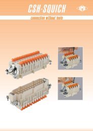
<strong>MIXO</strong><br />
frames <strong>for</strong> <strong>modular</strong> units<br />
● die-cast zinc alloy frames<br />
● with VDE ground contacts<br />
● possibility of mounting female and male <strong>modular</strong> units<br />
on the same frame<br />
● frames supplied with lock-in tab to attach units<br />
● polarisation on frames<br />
● code pins CR..CX<br />
Warning<br />
the module support frames are marked:<br />
- with upper-case letters A-B, A-C, A-D and A-F<br />
(<strong>for</strong> use in hoods)<br />
- with lower-case letters a-b, a-c, a-d and a-f<br />
(<strong>for</strong> use in housings)<br />
Positioning the modules in the frames according to the<br />
respective letters is ensuring the specular assembly of<br />
modules, <strong>for</strong> which the hood will be coupled correctly to<br />
the housing.<br />
frames <strong>for</strong> <strong>modular</strong> units<br />
frames <strong>for</strong> <strong>modular</strong> units with<br />
lock-in tabs<br />
description part No. part No. part No.<br />
<strong>for</strong> CZ enclosures, size 49.16<br />
CX 01 T<br />
frames <strong>for</strong> <strong>modular</strong> units type <strong>for</strong> hoods type <strong>for</strong> housings<br />
(module lock-in tabs included)<br />
- <strong>for</strong> 2 <strong>modular</strong> units CX 02 TM CX 02 TF<br />
- <strong>for</strong> 3 <strong>modular</strong> units CX 03 TM CX 03 TF<br />
- <strong>for</strong> 4 <strong>modular</strong> units CX 04 TM CX 04 TF<br />
- <strong>for</strong> 6 <strong>modular</strong> units CX 06 TM CX 06 TF<br />
lock-in tabs <strong>for</strong> <strong>modular</strong> units<br />
(6 units) dividable CX CFM<br />
polarisation of frames with relative identification<br />
letters and couplings<br />
frame <strong>for</strong> hoods 1) frames <strong>for</strong> housings 1)<br />
dimensions in mm<br />
49.5 16<br />
dimensions in mm<br />
A 27<br />
part No. A (mm) <strong>for</strong> housings size<br />
CX 02 TM / TF 44 44.27<br />
CX 03 TM / TF 57 57.27<br />
CX 04 TM / TF 77.5 77.27<br />
CX 06 TM / TF 104 104.27<br />
- large earth terminal <strong>for</strong> cables from 4-6 mm 2 , AWG 12-10<br />
- small earth terminal <strong>for</strong> cables from 1-2,5 mm 2 , AWG 18-14<br />
position of modules (contact side view)<br />
side with reference arrow ▲<br />
22.3 *)<br />
*) distance <strong>for</strong> electric contacts: max 24 mm<br />
distance <strong>for</strong> pneumatic contacts: max 23.5 mm<br />
frames <strong>for</strong> hoods<br />
frames <strong>for</strong> housings<br />
19.5 2)<br />
side with reference arrow ▲<br />
When two or more identical <strong>connectors</strong> of the <strong>MIXO</strong><br />
1) the frames can be used either in hoods or housings,<br />
series are used, coded pins are used prevent incorrect<br />
<strong>for</strong> a correct coupling please use both frame types<br />
coupling (CR...CX series).<br />
(one with upper-case letters and the other with<br />
lower-case letters)<br />
CX CFM<br />
2) distance <strong>for</strong> electric and fibre optic contacts:<br />
5<br />
max 21 mm<br />
distance <strong>for</strong> pneumatic contacts: max 20.5 mm 88.2<br />
dimensions shown are not binding<br />
and may be changed without notice<br />
4<br />
8
IMPORTANT NOTES<br />
The products in this catalogue cannot guarantee the best functionality on installation, as this depends mainly on their<br />
correct "installation into service" which must be per<strong>for</strong>med in compliance with the applicable system safety standards and<br />
according to the "rule of the art".<br />
The products shown in this catalogue are deemed to <strong>for</strong>m connections mainly <strong>for</strong> electrical circuits, there<strong>for</strong>e they have<br />
to be assembled according to the user's best choice <strong>for</strong> the different applications.<br />
For such choices, as well as <strong>for</strong> uses of single components and/or <strong>for</strong> uses with purposes other than those herein<br />
declared, I.L.M.E. SpA refuses any liability <strong>for</strong> the application results and/or <strong>for</strong> product incorrect use and/or<br />
unsuccessful per<strong>for</strong>mances.<br />
The <strong>connectors</strong> must not be connected or disconnected when live or under load.<br />
After wiring the <strong>inserts</strong> we recommend to verify the protective earth terminals continuity.<br />
The connector <strong>inserts</strong> operation is guaranteed only if mounted by four screws on a rigid plane (provided by<br />
hoods/housings).<br />
I.L.M.E. SpA is not responsible <strong>for</strong> any different application.<br />
The installer must verify and ensure the correct coupling and operation of the protective earth connection.<br />
For all <strong>inserts</strong> with screw-type terminals it is important that the correct torque is applied to the screws in order to prevent<br />
damage to the conductor, the screw or the terminal.<br />
Crimping tools and contacts should be supplied by the same manufacturer.<br />
The termination of spring-clamp connector <strong>inserts</strong> is guaranteed only when the specified screwdriver is correctly used <strong>for</strong><br />
actuating the spring (see indication in the specific catalogue and, where applied, on the insert) and the operating<br />
principles are followed.<br />
To prevent incorrect coupling please respect the polarity drawing (contacts side view) when two similar <strong>inserts</strong> are<br />
mounted in double-sized hood or housing. To avoid coupling mismatch we recommend the use of coding pins when two<br />
or more similar <strong>connectors</strong> are mounted close together.<br />
The complete <strong>connectors</strong> (enclosures and <strong>inserts</strong>) guarantee the IP degree of protection when coupled and locked with<br />
their closing levers. In order to ensure the same degree of protection provided by the connector housings, the cable<br />
glands or other accessories used to close cable outlets must also have at least an equivalent IP degree of protection.<br />
In order to prevent stress on the contacts, the <strong>connectors</strong> must be coupled and uncoupled in the axial direction with<br />
respect to the contacts, without bending and pulling the attached conductor bundles or cables.<br />
ILME <strong>connectors</strong>, <strong>inserts</strong> and enclosures are generally compatible with similar/equivalent products from other<br />
manufacturers, according to the last samples we tested.<br />
The full interchangeability cannot be granted by ILME as we cannot be considered responsible <strong>for</strong> technical changes<br />
made by other manufacturers.<br />
In particular, ILME cannot guaranteed the full per<strong>for</strong>mances of our IP68 enclosures (Series CG) if coupled with other<br />
manufacturers’ products.<br />
I.L.M.E. SpA takes no responsibility in verifying whether the components herein contained comply with the specific<br />
regulations of fields of application.