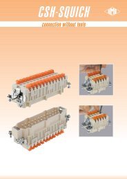
TM Interlocked Socket Outlets - AP Technology
TM Interlocked Socket Outlets - AP Technology
TM Interlocked Socket Outlets - AP Technology
- No tags were found...

You also want an ePaper? Increase the reach of your titles
YUMPU automatically turns print PDFs into web optimized ePapers that Google loves.
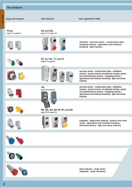
the productsoverviewplugs and couplerswith interlockmain application fieldsPlusopage 11 to page 37SQ and SQ...page 131 to page 143domestic - services sector - construction sites -shopping centres - agriculture and livestockbreeding - light industryPK, KI, PB...T1 and T2page 67 to page 87services sector - construction sites - exhibitioncentres - tourist resorts, recreational centres, sportsand entertainment centres - shopping centres -agriculture and livestock breeding - light and heavyindustry<strong>TM</strong>page 39 to page 65services sector - construction sites - exhibitioncentres - tourist resorts, recreational centres, sportsand entertainment centres - shopping centres -agriculture and livestock breeding - light and heavyindustryBE, BK, BA, BP, BI, BT and BCpage 150 to page 156hospitals - large-scale catering - harbour and navalworks - agriculture and livestock breeding -chemical industry - light and heavy industrysteel industry - large works -shipyards - large industries2
FMcases for distribution boardslight, resistant, compact and easyto handle structures with a largenumber of possible combinationspage 105 to page 129may be combined with:the Pluso seriesthe SQ and SQ... seriessystemsoverviewFCsupports and cases for distributionboardsstrong, modular and articulated structure,supports for the groupspage 89 to page 104may be combined with:the Pluso seriesthe SQ and SQ... seriesthe PK, KI series, PB...T1 and T2BKmodular system for distributionboardsespecially strong structures for usein severe, highly aggressive conditionswith degree of protection IP67page 145 to page 161may be combined with:the Pluso seriesPK...PB5, PK...LL,PB...A1 and A2socket-outlets in die-cast metallicenclosuresstrong structures for use in extremelysevere ambientspages 78-79-81-82may be combined with:the Pluso series<strong>TM</strong>interlocked switched socket-outletsand accessories for distributionboards and batteriesstrong structures for use in extremelysevere ambients withdegree of protection IP66/IP67page 39 to page 65may be combined with:the Pluso series3
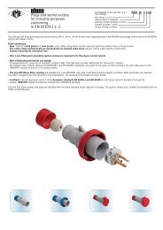
standards for low voltage plugs, socket-outlets and distribution boardsstandardsEN 60309-1 and EN 60309-2 standardsIn 1990, CENELEC (European Electrotechnical Standards Committee) introduced the provisions of the international publications IEC 60309-1 and IEC 60309-2 into the two correspondingEuropean standards EN 60309-1 and EN 60309-2 (classification CEI 23-12/1 and 23-12/2). IEC (International Electrotechnical Commission), the worldwide organisation forelectrotechnical standardisation had adopted these publications basing them almost entirely on the EEC 17 Publication of 1958, now withdrawn, issued by the now dissolved organisationCEEel, This is why still today this system of industrial sockets and plugs is traditionally called by many ”EEC”. The European standards EN 60309-1 and -2 were then compulsorilyadopted as national standards by all the CENELEC member states (which as from 1 May 2004, with the expansion of the EU, include Austria, Belgium, Cyprus, Denmark, Estonia,Finland, France, Germany, Greece, Ireland, Iceland, Iceland, Italy, Latvia, Lithuania, Luxembourg, Malta, Norway, Holland, Poland, Portugal, United Kingdom, Czech Republic, Slovakia,Slovenia, Spain, Sweden, Switzerland and Hungary). All conflicting national standards have at the same time been abolished.Today, therefore, the manufacture of plugs and socket-outlets for industrial use has been harmonised throughout Europe. Before its termination, CEEel’s members also includedBulgaria, Israel, former Yugoslavia (today Bosnia, Croatia, Macedonia, Serbia with Montenegro, Slovenia) and the former Soviet Union (today the Russian Federation).In virtue of the correspondence with the IEC publications, this industrial plugs and socket-outlets system is widely known and appreciated in leading non-European countries such asArgentina, Australia, Brazil, Canada, China, Korea, Egypt, Japan, India, South Africa, Turkey and the USA. In Italy the above harmonisation is regulated by standards EN 60309-1 andEN 60309-2. In 1999 the fourth editions of the IEC publications were adopted as EN by the CENELEC and published in Italy in 2000.The technical notes below and the products illustrated in the present booklet refer to series 1 versions, used in Europe on the basis of said European Standards and in countries ofEuropean technical-cultural origin (e.g.: most of Latin America, Australia, South Africa). A series 2 also exists, which differs for its rated current, voltage and frequency values and forits polarity and pole marking, adapting to North American installation standards and those of countries that have adopted this system (e.g. Mexico, Japan).The Provisions of the StandardsEach model of plug and socket is unique and hasa specific use. Each model has safety devicesthat make it impossible to insert a plug into asocket made for a different capacity, voltage, frequencyand number of poles.In the “low voltage” versions, the safety system isbased on two references:- a guiding groove on the socket that correspondsto a nib on the plug;- an earthing contact of increased capacity withrespect to the other contacts, and located in differenthour positions according to the voltagesused.The 63A and 125A plugs have a pilot contact foroperating an electric interlock.Hour Position (h)This position is determined by looking at the frontof the socket and placing the major guidinggroove at the 6 o’clock position and noting thehour position of the earthing contact.Following are examples of three different polaritieswith the earth contact at the 6 o’clock position.<strong>Socket</strong> - front viewL/+L1L1L2 major keyL2L3L3 major keyN major keyLow voltage over 50V up to 690VNumber frequency rated operating hour position (h) colourof poles voltage earthing contact (*)3P+N+m 3P+m2P+mHz V 16A and 32A 63A and 125A50 and 60 100 - 130 4 450 and 60 200 - 250 6 650 and 60 380 - 415 9 950 and 60 480 - 500 7 750 and 60 supply from isol. transf. 12 12100 ÷ 300 > 50 - -> 300 ÷ 500 > 50 2 -direct current > 50 - 250 3 3direct current > 250 8 850 and 60 100 - 130 4 450 and 60 200 - 250 9 950 and 60 380 - 415 6 660 440 - 460 ✰ 11 1150 and 60 480 - 500 7 750 and 60 600 - 690 5 55060380440 ❄3 -100 ÷ 300 > 50 10 -> 300 ÷ 500 > 50 2 -50 and 60 57/100 - 75/130 4 450 and 60 120/208 - 144/250 9 950 and 60 200/346 - 240/415 6 650 and 60 277/480 - 288/500 7 750 and 60 347/600 - 400/690 5 560 250/440 - 265/460 ✰ 11 115060220/380250/440 ❄3 -100 ÷ 300 > 50 - -> 300 ÷ 500 > 50 2 -all rated operating voltages and/or frequenciesall types not covered by other configurations 1 1✰ Mainly for marine installations❄ Only for refrigerated containers (standardised by ISO)(*) The positions indicated with dashes “-” are not standardised(**) Colour according to voltage(***) If necessary, green may be used together with the colour of the operating voltage for frequenciesof over 60 Hz up to 500 Hz inclusiveyellowblueredblack(**)(***)(***)(**)(**)yellowblueredredblackblackred(***)(***)yellowblueredblackblackredred(***)(***)(**)4
standards for low voltage plugs, socket-outlets and distribution boardsstandardsThe Provisions of the StandardsEach model of plug and socket is unique and hasa specific use. Each model has safety devicesthat make it impossible to insert a plug into asocket made for a different capacity, voltage, frequencyand number of poles.In the “extra-low voltage” versions with no earthingcontact, the safety system is based on tworeferences:- a guiding groove (key way) on the plug that correspondsto a nib on the socket (major key) thatis fixed at the 6 o’clock position- another groove on the plug (minor key) and anib on the socket (minor key) that can be positionedon different hours, according to the operatingrequirements.Hour Position (h)This position is determined by looking at the frontof the socket and placing the major key way atthe 6 o’clock position and noting the hour positionof the minor key. Following are examples of twodifferent polarities with the minor key at the 12o’clock position.Extra low voltage up to 50VNumber frequency rated operating hour position (h) colourof poles voltage minor key position (*)2PHz V 16A and 32A50 and 60 20 - 25 no key way50 and 60 40 - 50 12> 100 ÷ 200 20 - 25 and 40 - 50 4300 20 - 25 and 40 - 50 2400 20 - 25 and 40 - 50 3> 400 ÷ 500 20 - 25 and 40 - 50 11d.c. 20 - 25 and 40 - 50 1050 and 60 20 - 25 no key way50 and 60 40 - 50 12violetwhite(**)(**)(**)(**)whitevioletwhite<strong>Socket</strong> - front view3P> 100 ÷ 200 20 - 25 and 40 - 50 4300 20 - 25 and 40 - 50 2(**)(**) minor key400 20 - 25 and 40 - 50 3(**)L/+ major key> 400 ÷ 500 20 - 25 and 40 - 50 11(*) Positions 1, 8 and 9 are reserved for future standardisation. For constructional reasons, positions 5, 6 and 7 cannotbe used.(**) If necessary, green may be used together with the colour of the operating voltage for frequencies higher than 60 Hzup to 500 Hz inclusive.(**) minor keyL1L2L3 major keySize of connectable conductors according to EN 60309-1Conductor cross-sections in mm 2 usable in socket-outlets and plugsrated rated fixed plugs* (rigid or semi plugs and couplers (rigid or semi fixedoperating current rigid conductors) plugs rigid conductors)voltage min max min max16A 1. 5 4 1 2.5over 50V 32A 2.5 10 2.5 6up to 690V 63A 6 25 6 16125A 25 70 16 50up to 50V16A 4 10 4 1032A 4 10 4 10For pilot contacts (63A ad 125A socket-outlets and plugs), refer to the conductors which can beused in the 16A socket-outlets and plugs with a rated voltage of over 50V.* It is also possible to connect flexible conductors to fixed sockets and plugs. The equivalent sectionof the flexible conductor is generally one size smaller than the rigid or the semi rigid conductor.Please refer to EN 60309-1 and -2 norms.Use of multipolar cables according to EN 60309-1Min. and max. diameters of cables which clamped in couplers and plugsrated rated approximate external cable ø in mmoperating current (cables type HO5 RR-F and HO7 RN-F)voltage min max16A 8.1 15.3over 50V 32A 11.5 21.3up to 690V 63A 17.3 31.3125A 26.0 48.8up to 50V16A 13.5 22.832A 13.5 22.85
standards for low voltage plugs, socket-outlets and distribution boardsstandardsEN 60439-1 1) and EN 60439-3 standardsThe low voltage distribution boards, known as “assemblies” by the definitions in EN60439 standard, contain the switchgear (for isolation, switching), protective devices(automatic circuit-breakers, fuses), and controlgear (for command, control and measurement),and are rarely suitable for mass-production.The mass-production of these boards is not cost-effective, given the great number ofinstallation possibilities which are unlikely to fall within a limited number of models.In the past the board (defined a gswitchgear and controlgear assemblyh) used to bemore often a typical custom-built production. The electrical, thermal and mechanicalcoordination requirements, with the exception of the implementation of anti-accidentmeasures, were completely neglected, given the lack of technical standards whichwould define the state of the art.The concept of state of the art was introduced as a legal term of reference (in Italy bylaw no. 186 of 1968) but for gassembliesh it was left to the free judgement of thedesigner, the manufacturer and the installer of the board itself.The Technical Committee 17 (Switchgear and Controlgear) of the Italian NationalElectrotechnical Committee (CEI) tried to compensate for this lack of reference withthe first edition of the CEI 17-13 (1980) Italian standard, although this one only coveredthe “factory-built assemblies”, i.e. those mass-produced assemblies for which itwas technically feasible and economically acceptable to introduce a series of typetests. For the first time. the board was considered a product and not a miniature system.The standardisation of the board equipment (switchgear and controlgear such asswitches, disconnectors, automatic circuit-breakers, contactors, etc.) has in themeantime reached such level as to make the “modular” construction of the boardspossible. The electrical, thermal and mechanical performance of these structures canbe estimated by calculation within acceptable limits, thus avoiding costly tests andcertifications.Hence the need for a detailed standard, also applicable to custom-built boards,obtained by assembling components whose behaviour can be inferred by what isdeclared by their manufacturers or may refer to a prototype submitted to a full cycleof type tests.The second edition of the Italian standard for gassembliesh CEI-17-13 of 1991 is nowa harmonised European Norm known as EN 60439-1. It introduced the classificationof boards into TTA type-tested assemblies (more likely mass-produced 2) ) and PTTA,partially type-tested assemblies (more likely custom-built in small quantity or in a singleunit 3) ). For the first of these (TTA), the standard prescribed costly and technicallydifficult laboratory tests, while for the second (PTTA), it prescribed checks consistingof simple instrumental measurements accessible to small manufacturers and/orinstallers, and of deductions gathered from the data of the manufacturers of the components(switchgear and controlgear devices and enclosures). The third edition of theEN 60439-1 standard (CEI 17-13/1, 1995), and more recently the fourth edition,improved this strategy 4) . At the same time deductive methods were introduced for thePTTA boards to avoid carrying out the most difficult tests (technical report CEI17-52 5) ,short-circuit withstand; publication CEI 17-43 6) , heating) starting from data of similarsystems which have been submitted to type-tests (TTA boards). The standardbestows equal value to the boards tested by the manufacturer using type tests andthose deriving from the latter, verified via calculations.For the a.c. enclosed distribution boards (DBU) to be used indoors, with voltage toearth up to 300V a.c., which are stationary, intended to be used either in domestic(household) applications or in places where unskilled persons have access for theiruse, the particular prescriptions of standard EN 60439-3 of 1992 are applied, integratedby amendment EN 60439-3 A1 of 1995 and by the more recent amendmentEN 60439-3/A2: 2001-10.This norm deals with small and medium distribution boards of the type referred toabove with input rated current up to 250A and currents on single output circuits up to125A, and only of the fully type-tested type (also referred to as mass-produced) withtype tests (TTA), but declared itself not applicable to PTTA boards.If the general standard EN 60439-1 therefore allows fully type-tested assemblies(TTA) and partially type-tested assemblies (PTTA), the particular standard EN 60439-3 is stricter for DBU distribution boards with the aim of enhancing the safety of“unskilled persons”, or (IEC 64 8/2) those classified as instructed (with the necessaryknowledge to prevent risk from an electric system) and advised (who have receivedthe necessary information from an instructed person with the aim of preventing risk).A distribution board to be classified as DBU, which may be used by a person who hasnot been instructed or advised, loses this negative feature simply by preventing itsuse by locking it up and giving the key to a trained person.In this way, in homes and similar places, where a DBU board would be necessary, itis possible to install a PTTA board with suitably restricted access to the controls.But the manufacturer of PTTA distribution boards lacks a set of reference standardsexcept for EN 60439-1, that is, the general part.The experimental Italian standard CEI 23-51Given the need to define safety prescriptions for PTTA distribution boards in order forthem to be considered as gstate of the arth in accordance with the Italian law (a needthat in Italy has stemmed from law no. 46 of 1990 dealing with the safety of installationsof any kind in buildings) SC23B/C of the Italian National ElectrotechnicalCommittee CEI, based upon standard CEI 23-48 8) drew up two experimental standards,namely CEI 23-49 9) and CEI 23-51 10) .With CEI 23-51, in force in Italy since April 1st 1996 and recently extended to its secondedition, the scope of CEI 23-48 is widened than in the original one whichincludes shunt boxes and flush-mounting boxes to hold switches and household socket-outlets,to cover also boxes for the so-called exchanges for household and similarinstallations (Inq < 32A) and distribution boards with three-phase power greater than90 kW.In fact, this standard applies to switchgear and controlgear assemblies with inputrated current Ine not greater than 125A 11) , to be used in alternate current with ratedvoltage no greater than 440V, with prospective rated short-circuit current not exceeding10 kA, or protected by current limiters with limited current not exceeding 15 kA attheir rated breaking capacity.This standard establishes the prescriptions for the production, checking and testingof stationary distribution boards for household and similar use, consisting of an enclosureand one or more devices. In particular, it provides a deductive method for thecheck of the temperature-rise limits (30˚K) knowing the maximum power dissipatedby the enclosure Pinv and that dissipated by the devices incorporated.To make boards which include equipment with non-negligible thermal dissipation, thestandard entails the use of enclosures complying with the experimental Italian standardCEI 23-49.Standard CEI 23-49 adds to the safety prescriptions of the general standard CEI 23-48 12) on enclosures for boards for household or similar use, the performance prescriptions,which oblige the manufacturer of the enclosure to verify and declare themaximum dissipating power of the enclosure Pinv for the 30˚C maximum permissibletemperature gradient.1)A radical review of the IEC 60439 standards is already at an advanced stage,and will be allocated the numbering IEC 61439 .2)TTA = type-tested assemblies3)PTTA = partially type-tested assemblies4)The fourth edition of standard CEI EN 60439-1 has been in force since 1January 2001, but up to 1 August 2002 it remained in force together with the 3 rdedition. The few changes made relate to:- details of the four segregation forms, useful to differentiate cases of access tothe board for maintenance purposes, thus improving protection against directcontacts;- specification of the direction of manoeuvre of the equipment to be determinedon the basis of the risk of manoeuvring errors;- exemption from the short circuit test for board circuits whose top current is limited to below 17 kA (previously 15 kA) with regard to the assumed maximumshort circuit current at the terminals of the board’s entry circuit;- resistance between the protective earthing circuit and the board’s exposed conductive parts below 0.1 Ω5)CEI 17-52 (1994, reprinted in 1997-08) A method of assessing the ability of partiallytype-tested assemblies (PTTA) to withstand short-circuits. It is equivalent toIEC 61117: 1992-2.6)CEI 17-43 (2000-08) A method of temperature-rise assessment by extrapolationfor partially type-tested assemblies (PTTA) of low voltage switchgear and controlgear.It is equivalent to technical report IEC/TR3 60890:1987-07 + IEC/TR360890 EC:1988-03 + IEC/TR3 60890/A1:1995-05 and to document CENELECHD 528 S2:1997-01.7)Reprinted by CEI in consolidated form as CEI EN 60439-3 (1997-07), booklet 3445 C.8)CEI 23-48 (1998-02) Enclosures for stationary equipment for household and similaruse - Part 1: General prescriptions. This is the non-amended reprint of thefirst edition 1995-12. It was published in Italy, with the authorisation of CEN-ELEC, owing to the delay in the advancement of the European project prEN60670 (equivalent to IEC 60670:1989-11 + IEC 60670/A1:1994-07). It wasrecently ratified by CENELEC, and therefore the new, equivalent standard EN60670-1: 2004 will soon be published with amendments to standard IEC 60670-1:2002-12.9)CEI 23-49 (1996-03) Enclosures for stationary equipment for household and similaruse - Part 2: Specific prescriptions for enclosures designed to contain protectiondevices and equipment which disperse considerable power during normal use.It is integrated by amendments CEI 23-49;V1 (2001-12) and CEI 23-49;V2 (2003-06).10)CEI 23-51 (2004-02, 2 a Ed.) Prescriptions for the production, checking and testingof stationary distribution boards for household and similar use. Published experimentallydue to the CENELEC prohibition to publish autonomous national standardswithout prior notification to CENELEC. The regulations it contains are thereforevalid only in Italy.11)Sum of the rated current of all the protective and/or switching devices placed at theinput, intended to be used simultaneously, multiplied by the simultaneity factorK e assumed equal to 0.85.12)In the interest of safety, therefore of the presumed conformity to the Low Voltagedirective 73/23/EEC and further modifications, conformity to standard CEI 23-48 issufficient.6
standards for low voltage plugs, socket-outlets and distribution boardsNormal service conditions for electrical equipmentThe standard EN 60439-1 applies to low-voltage switchgear and controlgear assemblies,commonly known as low-voltage boards, with rated voltage not exceeding1000V (with frequency not exceeding 1 kHz, although boards for greater frequenciesare allowed under further specific prescriptions) or 1500V in d.c.This standard defines the equipment (boards) for indoor and outdoor use in accordancewith the installation conditions. The normal service conditions are in factdefined for indoor and outdoor use.These normal conditions are also used as reference in standard EN 60664-1 (basicsafety publication) for the coordination of insulation. This coordination consists of thedefinition of the rated insulation values of electrical equipment and the correspondingcomponents relating to:- dielectric characteristics of the insulating materials used- degree of pollution in the environment where they are to be used- overvoltage category of the point at which they are connected to the network (distancefrom the generating centres).1. Ambient air temperatureIn normal indoor service conditions the temperature should not be lower than -5 ˚Cor greater than +40 ˚C and the average value over 24 h should not exceed +35 ˚C.For outdoor installations the minimum value is -25 ˚C in mild climates and -50 ˚C inarctic climates (with the possibility of an agreement between manufacturer and userin the latter case).2. AltitudeThe altitude of the installation site should not exceed 2000 m. For equipment to beused at higher altitudes it is necessary to consider the reduction of dielectric rigidityand the cooling effect of the air. For installations in different conditions refer to themanufacturer.3. Atmospheric conditions:humidity and pollutionThe relative humidity of the air should not exceed 50% at a maximum temperature of40 ˚C. Higher relative humidity values are allowed at lower temperatures, for example:90% at +20 ˚C. For outdoor installations the relative humidity may reach 100% ata maximum temperature of +25 ˚C.Degrees of pollutionIP degree of protection and the EN 60529 standardThe minimum IP degree of protection is regulated by the CEI 64-8 installation standards(inclusion of the harmonisation documents of the CENELEC HD384 series andthe IEC 60364 publication) which, in part 7, cover a number of special environments:construction and demolition sites, structures designed for agricultural or livestockbreeding use, restricted conductor areas, caravans and caravan sites, environmentswith a greater risk in case of fire, public performance and entertainment areas, poolsand, in the future, fountains and marinas and harbour areas. The standard is applicableto enclosures for electric materials with a rated power no greater than 72.5 kW.All the equipment must be installed according to gstate of the arth rules and mustcomply with any manufacturer’s assembly instructions. When components of differentdegrees of protection are assembled, the resulting board or distribution system willassume the lowest degree of protection of the mounted components.This has been assessed and applies:- socket-outlets, when a plug of the same degree of protection is inserted or whenthe cover is closed (with counternuts tightened for IP67).- plugs (with counternuts tightened for IP67).- for cases, when all the covers are adequately closed.The range of ILME products presented in this catalogue offers the following range ofprotection:IP44: protection against the penetration of solid foreign objects with a diameterequal to or greater than 1 mm for protection against the intrusion of dangerousparts with an access calibre of Ø 1 mm (1 st digit), and protectedagainst the dangerous effects of water spray from all directions(2 nd digit).IP55: Protection against the penetration of harmful quantities of powder andagainst access to dangerous parts with an access calibre of Ø 1 mm (1 st digit)and protected against the dangerous effects of water jets with a nozzle fromall directions (2 nd digit).IP66: total protection against dust and access to dangerous parts with an accessibilitycalibre of Ø 1 mm (1 st digit), and protected against powerful waterjets such as sea waves (2 nd digit).IP67: Total protection against powder and against access to dangerous parts withan access calibre of Ø 1 mm (1 st digit) and protected against the effects of temporaryimmersion (30’) in water at a maximum depth of 1 meter (2 nd digit).The socket-outlets with IP55 degree of protection and those with double degree ofprotection IP66/IP67 14) have a bayonet jointed lid, traditionally defined as “water-tight”and require plugs with IP67 degree of protection (with counternut and gasket) to preservethe degree of protection marked on the apparatus.standardsThe pollution degrees define the environmental conditions. To go in more detail, standardIEC 60664-1 clarifies that pollution is defined as any contribution of foreign matter,whether a solid, liquid or gaseous (ionised gas), that may negatively affect thedielectric strength of the surface resistivity of the insulating material. Four degrees ofpollution are defined and are described by conventional numbers based on the quantityof polluting agent or on the frequency with which the phenomenon occurs thatreduces the dielectric strength and/or the surface resistivity.pollution degree 1: no pollution or only dry non-conductive pollution. The pollutionhas no influence.pollution degree 2: only non-conductive pollution except that occasionally a temporaryconductivity caused by condensation is to be expected.pollution degree 3: conductive pollution occurs or dry non conductive pollutionoccurs which becomes conductive due to condensation which is to be expected 13) .The pollution degree 3 refers to an industrial or similar environment.The pollution degree 2 refers to a household or similar environment.The third edition and the forthcoming fourth edition of EN 60309-1 standard (IEC60309-1) specifies that the normal use environment for the industrial plugs andsocket-outlets complying with this standard has a pollution degree 3 according tostandard IEC 60664-1.13)Pollution degree 4 was eliminated in the new standard edition as clearly illogical:conditions of persistent conductivity caused for example by conductive dust, rainor snow are definitely to be avoided throughout the project, and no isolating distanceis capable of withstanding them.14)The IP66/IP67 degree of protection will officially be introduced in the next amendment1 of the standards EN 60309-1 and EN 60309-2 (and of the relating IECstandards). It is already accounted for in the IP degree of protection standard EN60529 as a ”versatile” form of protection, covering the fact that the temporaryimmersion resistance test (protection IPX7) does not automatically comply with thetwo lower degrees of protection IPX6 and IPX5, tested with the respective jet tests.If the end user requires the equipment to resist both against temporary immersionsand pressurized water jets, declaredly IP66/IP67 devices with double markingmust be selected.1 st characteristic numeralPersonal protection against contact withhazardous partsIP External solid Protectionforeign bodiesnone0123456against solid foreignobjects with Ø greateror equal to 50 mm(e.g. hand)against solid foreignobjects with Ø greateror equal to 12 mm(e.g. finger)against solid foreignobjects with Ø greateror equal to 2.5 mm(e.g. tools and wires)against solid foreignobjects with Ø greateror equal to 1 mm (e.g.fine tools and wires)dust-protecteddust-tight2 nd characteristic numeralProtection of materials against harmfulpenetration of waterIP Tests Protection012345678noneagainstvertical dropsof wateragainstdrops of waterat an angle of 15°againstdrops of waterat an angle of 60°against water sprayedfrom all directionsagainst jets of waterfrom all directionsagainst powerful jets ofwater (such as seawaves)against the effect oftemporary immersion inwater at a depth of 1metreagainst the effects ofcontinuous immersion inwater7
guide to the selection of the socket-outlets, plugs and distribution board enclosuresselection guideResistance to chemical agentsThe information given below is valid for conditions of application at environmental temperatures no greater than 40 °C.The data provided in the table should be considered merely as a guide because the resistance of technopolymers that come upon contact with chemical agents depends uponthe concentration of the agent, the temperature at the time of contact, the mechanical stress involved and the duration of the contact.If the accessories and equipments are to be used in the presence of acids, bases, solvents or high concentration oils, contact our Technical Service. DepartmentTable of reactions to chemical agentschemical agentsAcids Bases Solvents Oils Fats FuelsitemsH 2 O (t up to 23 °C)Watery saline solutionConcentratesDiluted 15% maxConcentratedDiluted 15% maxAliphatic hydrocarbons(hexane)Aromatic hydrocarbon(benzene)Chlorinated hydrocarbonsand acetone (ketones)Ethyl alcohol (ethanol)SiliconeMineralVegetableAnimalSyntheticAnimal organic solutionUnleadedDieselPluso plugs and socket-outletsprecode PE, PEW, PB X X X X precode SIP, SIPW X X X precode PEM X X X X interlocked switched socket outlets SQ, SQx series, socket-outlets with safety transformer SQTprecodes SQ and SQx and SQT interlocked switched socket outlets in insulated enclosure, PK, KI series , and plugs with safety transformer in insulated enclosure PBseries PK...EB X X X Xseries KI...RI5 and KI...IB5 series PK...IA series PB...T1 and T2 X X X Xinterlocked switched socket outlets in metallic enclosure, PK series, and plugs with safety transformer in metallic enclosure PBseries PK...PB5 X X series PK...LL X X series PB...A1 and A2 X X group support platescodes FC...TB X X X X Xdistribution enclosures and FC modular equipment for groupscodes FC...DB / DB5 and GB5 FC board componentsFC series enclosures X X X X XFM board componentsFM series enclosures BK board componentsitems of the BK series , except 1) <strong>TM</strong> seriesall the items of the <strong>TM</strong> series 1)BP, BPR, Q, Q2 and RQ type modules (see reactions of the Pluso socket-outlets); BC 1734 R3T (see reactions of FM series).Legend = resistant = limited resistanceX = not resistantCorrosion and resistance to rustThe new edition of standard EN 60309-1 recommends for corrosion and resistance to rust the use of IP67 plugs and socket-outlets wherever corrosion could create problemson electrical parts and advises the manufacturer to consider the product specifically in terms of resistance to corrosion under specific operating conditions.To this end, socket-outlets and plugs with nickel-plated contacts are available upon request for applications in permanently dusty environments (e.g. cement and tile factories) or inenvironments with animal organic liquids (e.g. farms, agricultural and food processing industries). These socket-outlets and plugs and sockets have a greater resistance tocorrosion and greater sliding capacity, allowing the plug to be removed from the socket even under difficult conditions.Contact our sales offices for availability and price quotes.8
guide to the selection of the socket-outlets, plugs and distribution board enclosuresUse in electric systems in areas at risk of explosionThe electric systems which have come into existence since 1-7-2003 in work areas at risk of explosion due to the presence of gas, fumes, smoke or dangerous powders (excludingmines) must comply with European Directive 99/92/EC (a.k.a. ATEX 137). This is the so called ”social” part of the ATEX Directive 1) , adopted within the general directive89/391/EC on the subject of safety at work, implemented in Italy as the well know Law Decree n. 626/94 which merged with Law Decree n. 233/03 under Title VIII-bis.According to this directive (art. 8) employers must, among other things, develop and keep up to date the “Document regarding protection against explosions” in which they muststate:- that all explosion risks have been identified;- what measures will be taken to avoid the danger of explosions;- that the zones have been identified and classified (table A);- that the work equipment is suited to the type of area and that it is used and maintained in adequate working order. The Directive specifies (art. 9) the implementation timescale:The minimum provisions of Attachment II, part A apply to any equipment already existing as at 30-6-2003; as regards work areas already in use as at 30-6-2003, said minimumprovisions must be adapted by 30-6-2006. Finally, compliance with the provisions of Attachment II, Part A + B 2) is required as regards equipment purchased after 30-6-2003 andnew work areas in which explosive atmospheres may form.The Directive does not apply to medical areas, gas equipment, explosive substances, mines and land, river or air transport vehicles (vehicles intended for use in explosive atmospheresare not excluded).As regards equipment installed in the abovementioned locations, as from 1-7-2003 these must comply with Directive 94/9/EC (a.k.a. ATEX 95 and implemented in Italy asPresidential Decree n. 126 dated 23-3-1998). This applies to all equipment and protection systems intended for use in potentially explosive atmospheres (including mines). Twoequipment groups are envisaged: group 1, intended for underground mine use or for overground mine works (firedamp and/or combustible dust); group 2, all other locations.Attachment 1 of Directive 94/9/EC defines categories M 1 and M 2 for group 1 equipment, and the following three categories for group 2 equipment:- category 1 equipment (very high level of protection - zones 0 or 20);- category 2 equipment (high level of protection - zones 1 or 21);- category 3 equipment (normal level of protection - zones 2 or 22);Ex material sold or installed after 30-6-2003 must be marked EC and be accompanied by the EC conformity declaration, on the basis of this directive.selection guideStandard CEI 64-2 (1990-11, 4 th edition, Booklet 1431) governed applications in locations at risk of explosions in a mainly industrial context. So far the following EuropeanStandards have been published in an effort to harmonise said standard throughout Europe:HAZARDOUS AREAS DUE TO THE PRESENCE OF INFLAMMABLE FUMES OR GAS (ex class C1 and C3 areas)- CEI EN 60079-10 (2004-01, class CEI 31-30, 2 rd Ed.) “Electrical assemblies aimed at explosive atmospheres due to the presence of gas - Part 10: Classification of hazardouslocations”, in force, regarding the classification of hazardous places due to the presence of inflammable fumes or gas 3) ;- CEI EN 60079-14 (2004-05, class CEI 31-33) ”Electrical assemblies aimed at explosive atmospheres due to the presence of gas - Part 14: Electrical systems in areas at riskof explosions due to the presence of gas (other than mines)” in force, regarding provisions concerning electrical systems in areas at risk of explosion due to the presence ofgas (other than mines) 4) ;HAZARDOUS AREAS DUE TO THE PRESENCE OF COMBUSTIBLE DUST (ex class C2 areas)- CEI EN 50281-3 (2003-06, class CEI 31-52) ”Assemblies aimed at explosive atmospheres due to the presence of combustible dust - Part 3: Classification of areas where combustibledust is or could be present”, in force since 1-7-2003, regarding the ex class C2 areas of standard CEI 64-2 5)- CEI EN 50281-1-2 (1999-09, class CEI 31-36) called “Electrical assemblies aimed at explosive atmospheres due to the presence of combustible dust - Part 1-2: Electricalassemblies protected by enclosures - Selection, installation and maintenance”, definitively in force since 1-7-2003 6)These are the first of a large collection of CENLEC standards regarding electrical systems in areas at risk of explosion. They will be followed by other standards regarding theclassification of actually or potentially explosive areas due to the presence of explosives (ex class C0 area of standard CEI 64-2) and by standards regarding the safety requirementsof relating electrical systems, currently being developed by IEC and CENELEC. In particular, as from 1-1-1998 the definition of class C1 and C3 areas containing inflammablesubstances such as gas or inflammable liquids - i.e. excluding inflammable dust (class C2) and explosives (class C0) - is no longer in force: the relating chapters 3 and 5of standard CEI 64-2 have been abolished and replaced by the abovementioned standard CEI EN 60079-10. This introduces zone classifications, thus replacing the existingquantitative differentiation by a more analytical approach based on the degree of emission (three levels: continuous, primary or secondary) and on the degree of ventilation (threelevels: high, medium or low, with three further sublevels: good, average or poor). Zone extensions are determined through application guidelines and calculations.Zone 0: area with a continuous or prolonged explosive atmosphere due to the presence of gasZone 1: area where an explosive atmosphere due to the presence of gas may occur in normal operational conditionsZone 2: area where it is impossible for an explosive atmosphere due to the presence of gas to occur in normal operational conditions or where, should this occur, it may onlyoccur infrequently and for short spaces of time. Standard CEI EN 60079-14 replaced standard CEI 64-2 as regards the requirements of the electrical systems installed in areascontaining gas or inflammable liquids. In particular, since 30-11-1999 it has abolished chapters VII (AD-PE systems), VIII (AD-SI systems), IX (AD-I systems), XI (AD-FE systems)and XIII (AD-S systems), resulting therefore in the disappearance of the above types of safety electrical systems as described and defined by standard CEI 64-2. StandardCEI EN 50281-3 (2003-06, 1 st ed.) resulted in the further abolishment of chapter IV of standard CEI 64-2 7) , with standard EN 50281-1-2 (1999-09, 1 st ed.) substituting all parts ofthe chapters I, II, VI, X, XII and XIV regarding provisions for areas where combustible dust is or may be present (class C2 areas). Therefore only chapters I, II, VI, X, XII and XIVof standard CEI 64-2 remain in force, concerning specific provisions for the presence or development of explosive substances (class C0) while awaiting corresponding Europeanstandards.Standard CEI 64-2/A was abolished in 1-9-2001 with the publication of Guides CEI 31-35 (2001-01, 2 nd ed.) and CEI 31-35/A (2001-01, 2 nd ed.).Therefore it is no longer possible to use withstanding functional safety systems (AD-FT) in ex C2 areas (ex chapter XII).Most of the situations that used to allow this installation solution are classified as non-explosive (NE), in line with the new area classification. Therefore, in thesecases no particular adjustment is required either for new systems or for those existing before 30-6-2003, as these do not fall within Ex zone classifications in linewith the latest ATEX directives.As regards areas that would now need to be classified as Ex in line with the abovementioned ATEX Directive 137 (99/92/EC) in force since 1-7-2003, such as zone 2 or 22, newsystems require category 3 Ex electrical material, whereas systems existing before 30-6-2003 need to be adapted using said ATEX certified material by 30-6-2006.Given that in any case existing electrical systems constructed in line with the provisions of standard CEI 64-2 provide the same level of safety as those constructed in line withthe new standard CEI EN 60079-14, the table below contains indications for selecting AD-FT system components, exclusively for class C0 areas (presence of explosive substances),as inferred from standard CEI 64-2. Said table will remain valid until the publication of standards that abolish chapters I, II, VI, X, XII and XIV regarding said areas.1) ATEX = ATmosphere Explosive.2) Attachment II - Part B = equipment category selection criteria on the basis of the zone classification: zones 0 or 20 require category 1 equipment; zones 1 or 21 require category1 or 2 equipment; zones 2 or 22 require category 1, 2, or 3 equipment.3) The 1 st 1996-10 edition, in force since 1-11-1996, will remain simultaneously in force until 1-10-05.4) The 1 st 1998-01 edition, in force since 1-03-1998, will remain simultaneously in force until 1-6-06.5) Should be replaced with the European Standard prEN 61241-10 project ”Electrical apparatus for use in the presence of combustible dust - Part 10: Classification of areaswhere combustible dust is or may be present”, based on a similar IEC project.6) Integrated by amendment EN 50281-1-2/A1 (2004-06), it should be replaced by the European Standard prEN 61241-14 project ”Electrical apparatus for use in the presenceof combustible dust - Part 14: Selection and installation”7) Already reprinted by the CEI in March 2001, once again as 4 th edition, Booklet 5964 C.9
guide to the selection of the socket-outlets, plugs and distribution board enclosuresselection guideTables for selecting the type of environmentclass of the hazardous area(Italian standard CEI 64-2, Edition IV, 2001-03)qualification of the “AD” area 1)Minimum IP required by the standardC0C0ZRIP44product series degree of protection items product eligibility (see notes)PLUSO socket-outlets IP44 precode PE, SIP *)IP67 precode PEW, SIPW *)SQ... interlocked switched socket-outlets IP44 precode SQ, SQE, SQV, SQA IP55 code SQE....5, SQV...5, SQA...5 PK / KI interlocked switched socket-outlets IP44 code PK..EB IP55 code KI..RI5, KI..IB5, PK..PB5 BK interlocked switched socket-outlets IP67 precode BK, BE, BA <strong>TM</strong> interlocked switched socket-outlets IP66/IP67 code <strong>TM</strong>...IT/IS/IR/SP/KIS/KIR/KSP <strong>TM</strong> interlocked switched socket-outlets IP66/IP67 code <strong>TM</strong>...SIT/SIS/SIR/SSP/KSIS/KSIR/KSSP 2) PK socket-outlets with electric interlock IP55 code PK...IA, PK...LL socket-outlets with safety transformer IP44 code PB...T, PB...A IP55 code SQT 16220 IP67 code BT 16220, BT 16380 IP66/IP67 code <strong>TM</strong> 16220 T1/ST1 2) FC distribution enclosures IP44 code FC 1114 DB, FC 1414 DB IP55 code FC 1114 DB5, FC 1414 DB5 cases for modular equipment IP55 code FC...GB5 FC series cases and components IP55 all **)FM series cases and components IP55 all **)BK series cases and modules IP67 codes BC... <strong>TM</strong> series cases and modules IP66/IP67 codes <strong>TM</strong>... 1) Locations with explosion risks and the relating AD areas are classified by standard CEI 64-2, 4 th edition.2) When assembled on <strong>TM</strong> series ILME box (single, double or triple).NotesLegend*) plugs usable together with interlocked sockets = eligibleof eligible degree of protection = greater than the requirement**) only types for assembling interlocked socket-outlets, in the event of X = not eligiblecreating distribution boards with socketsAccording to standard CEI 64-2, so far devices with degree of protection IP44 or IP55 have been used in class 2 locations (presence of dust). In line with the new standards,we have introduced further requirements, such as thermal constraints, and the manufacturer must certify the device as an Ex product, according to the procedure indicated inthe latest ATEX directive (94/9/CE, implemented in Italy as DPR 23-3-1998 no. 126).Standard EN 50281-1-2(class. CEI 31-36) relates to electrical assemblies protected by enclosures, due to the presence of dust, and contains the following zone classification:Zone 20: area where an explosive atmosphere, in the form of a combustible dust cloud in the air, is present permanently or for long periods of timeZone 21: area where an explosive atmosphere, in the form of a combustible dust cloud in the air, is likely to be occasionally present during normal operationsZone 22: area where an explosive atmosphere, in the form of a combustible dust cloud in the air, is not likely to be occasionally present during normal operations but where, ifthis were to occur, it would only be present for a short space of timeConstruction selectionElectric systems in ex class 3 areasAs we have already mentioned, class 3 locations (presence of gas or of inflammable liquids in small quantities) are no longer covered by the above new European standards.The standards EN 60079-14 (gas) and EN 50281-3 (dust) do not include systems of type AD-FT. With the new classification criteria, all well ventilated areas with seconddegree emission sources (most of the ex C3Z2 areas, for which the AD-FT system was allowed) are now considered non hazardous areas in terms of explosions (area 2 NE);for these areas all ILME material indicated in the table is suitable with the new standard.The electrical systems in the ex C1ZR areasThe ex C1ZR areas, areas compliant (ZR) with class 1 locations containing gas or inflammable liquids, are no longer envisaged by the European Standard EN 60079-10.In most cases, as these areas are many metres away from the second degree emission sources (ex hazardous centres), in line with the new classification they are now nonhazardousareas in terms of explosions (area 2 NE); as regards these areas, all ILME material is suitable with the new standard.The electrical systems in the ex C1Z2 areasWith the new classification, ex C1Z2 areas surrounding the second degree emission sources often become 2 NE areas. As a result, with the exception of the immediate areassurrounding the point of emission, the area is only dangerous because of “its increased fire risks” (standard CEI 64-8/7 Sez. 751). In this case, all the ILME material indicatedin the table is suitable with the new standard.Electric systems in vast areas containing gas or inflammable liquid emission sourcesUnlike the old standard CEI 64-2, the latest European Standard EN 60079-10 does not envisage the extension of the AD area to the entire internal area. It specifies dilutionvolume calculations. As a result, at a certain distance from the emission centres the environment in these vast areas is no longer considered explosive. Here, where previouslyEEx assemblies were required, now the ILME materials indicated in the table are suitable with the new standard.10
<strong>TM</strong> interlocked switched socket-outlets for industrial useGeneral characteristicsThis chapter illustrates the characteristics of <strong>TM</strong> series interlocked socket-outlets.These socket-outlets offer tested reliability and can be used, in combination with specialcomplementary parts and PLUSO industrial plugs, as modular integrated systemsto configure distribution systems with industrial socket-outlets.These socket-outlets are designed to be used for:- Industrial applications- Service applications (trade fairs, exhibitions, etc.)- Agricultural and livestock breeding applications- Residential and similar applications (i.e. common areas of condominiums, cellars,garages, community buildings, kitchens, etc.)<strong>Socket</strong>-outlets and plugs for industrial use should be selected according to the followingparameters:• Rated current of the device to supply with the plug and socket-outlet coupling• Rated supply voltage, type of current (AC or CD), rated frequency, and type of distribution(single or three-phase, with or without neutral) to determine the numberof poles and hour positionThe 1 hour position is available for all 50V voltages and voltage ranges > and forfrequencies and frequency ranges not covered by standards• Type of installation (fixed or mobile) to determine the construction type of plugsand socket-outlets (flush-mounting, straight or inclined, wall-mounting, mobile,mobile angled)• The site of installation to determine the degree of protection (IP44 or IP67) andvoltage (in some areas installation standardsrequire very low safety voltage) <strong>TM</strong> socket-outlets come with base box for flush- orwall-mounting or without box for the assembly on single or multiple <strong>TM</strong> ILMEboxes (available on request). This enables to configure distribution boards at alater stage. The following types of socket-outlets are available:with insulating enclosure with base box:- <strong>TM</strong>..IT types with interlock and plug-type fuse carrier- <strong>TM</strong>..IS/KIS types with interlock and sectionable fuse carrier- <strong>TM</strong>..IR/KIR types with interlock and compartment for modular units- <strong>TM</strong>..SP/KSP types with interlock (without fuse carrier)- <strong>TM</strong>..T1 types with safety transformer (for extra-low voltage, SELV 24V AC)with insulating enclosure without base box (only for 16A and 32A socket-outlets):- <strong>TM</strong>..SIT types with interlock and plug-type fuse carrier- <strong>TM</strong>..SIS/KSIS types with interlock and sectionable fuse carrier- <strong>TM</strong>..SIR/KSIR types with interlock and compartment for modular units- <strong>TM</strong>..SSP/KSSP types with interlock (without fuse carrier)- <strong>TM</strong>..ST1 types with safety transformer (for extra-low voltage, SELV 24V AC)The type references of these last types is the same as those of models with boxes.Types with base box can be wall-mounted or flush-mounted, if required.The high solidity of boxes and materials used enable these products to be installedin reinforced concrete casts.Installers shall be responsible for performing the electric connections, preparing theentry holes on the boxes using the centering points on the sides, and for completingthe installation using hardware with a suitable degree of protection.The class of IP protection of the equipment will be equivalent to that resulting fromthe compliance with workmanship procedures and from the use of cable entries withan equivalent or higher IP degree of protection.The degree of protection of the equipment is always equivalent to the lowest one ofthe installed units.Types without base boxes can be mounted on existing and installed single or multipleboxes or on new ones, which can be purchased separately.<strong>Socket</strong>-outlets can also be fitted with specifically designed complementary parts toconfigure group distribution systems suitable to meet all possible installation needs.<strong>Socket</strong>-outlets can be fitted with:- Back plates in two sizes (depending on the size of the socket-outlet enclosure), suitablefor the assembly of socket-outlets with boxes or boxes for future expansion- Boxes for modular units like protection and control equipment- Junction boxes for socket-outlets or boxes- Modular pre-assembled bases- Single or multiple boxes for the subsequent installation of <strong>TM</strong> socket-outlets forboard mounting<strong>Socket</strong>-outlets and boxes for modular units (boxes with compartment for modularunits) are suitable to be used to spring-lock modular units (17.5 mm base modules)with sized DIN-rail EN 60715 TH 35-7.5.For information on the number of modules and maximum power that can be dissipated,see Table 1.<strong>Socket</strong>-outlet electric characteristicsrated frequency:0 Hz (direct current), and from 50 Hz to 500 Hzrated operating voltage:the standard identifies two main types of use:- Extra-low voltage socket-outlets (and related plugs), (SELV safety requirements, inaccordance with the CEI 64-8 installation standard), for max. rms voltage values of50V- Low voltage socket-outlets (plugs) for rms voltage values above 50V, up to a maximumof 690Vpolarity:models are designed with:- 2 poles (extra-low voltage, 2P)- 3, 4 and 5 poles (low voltage, 2P+m, 3P+m, 3P+N+m);63A socket-outlets (and related plugs) also have an additional pilot contactrated current:with 16A, 32A and 63A values (low voltage)rated insulation voltage:- 690V for low voltage socket-outlets parts. The rated insulating voltage of the wholeassembly generally corresponds to that of the lowest component and is limited to500V thanks to the presence of IS/SIS and IT/SIT fuse carriers.- 50V for extra-low voltage parts (T1/ST1 types always have an insulated transformerwith a rated insulation voltage of 230V on the primary circuit)minimum surface insulation distance:6 mm for max. rated operating voltages of 500V (EN 60309-1)minimum air insulation distance:6 mm for maximum rated operating voltages of 500Vbreaking capacity:socket-outlets have mechanical interlocks that prevent the plug being removed whilevoltage is present or from being inserted when the socket-outlet is live. This explainswhy no breaking capacity is required. The socket-outlets parts (inserts and holes) arethe same as those of the Pluso series and have therefore a breaking power 1.25times the rated current and 1.1 times the rated operating voltage.rated shortcircuit current based on fuse:10kAelectromagnetic compatibility:these units do not fall within the field of application of the EMC Directive, except forsocket-outlets with safety transformer (T1/ST1 types).- Immunity: in ordinary operating conditions, these units are not affected by electromagneticnoise. This may not apply if the installer has fitted devices that are sensitiveto electromagnetic noise in ordinary operating conditions.- Emissions: all units are designed for continuous use and do not generate electromagneticnoise in ordinary operating conditions. This may not apply if the installerhas fitted devices that generate electromagnetic noise in ordinary operating conditions.Mechanical characteristics- mechanical resistance to impacts20J (IK10 in accordance with EN 50102)- resistance to chemical agentssee Table on page 8- degree of protectionIP66/IP67 according to EN 60529 (see information note on pages 7 and 40)- maximum dissipating power of the enclosuresee table on page 40- resistance to glow-wireself-extinguishing capacity compliant with IEC 695-2-1 (glow-wire) for enclosures650 °C; for inserts 960 °C (value specified in standard: 850 °C)- temperatureambient: -25 °C - +40 °C; limit of materials: -40 °C - +125 °C- self-extinguishing capacityUL 94 classification- for enclosures (boxes and/or covers of fixed socket-outlets, enclosures of mobileplugs and socket-outlets): 94V-2 and 94HB- for 16A and 32A inserts (socket-outlet and plug): 94V-2- for 63A and 125A inserts (socket-outlet and plug): 94-5VA and 94V-0Materials- Inserts in insulating self-extinguishing thermoplastic material- Enclosures in insulating self-extinguishing thermoplastic material MIL.BOX ® , printedwith BC-MUL ® system, RAL 7012 grey- Anti-aging elastomer gaskets- Self-centering elastic brass contact tubes with zinc-plated steel spring- Fixing retainer screws in stainless steel with cylindrical head and mixed slots for 8x1screwdrivers and Ph2 cross screwdrivers- Terminals with zinc-plated screws retained in their seats when unscrewed- 32A, 63A and 125A socket-outlets with two fixing screws in the terminals as protectionagainst accidental loss- Terminals of 63A and 125A socket-outlets fitted with lead protection plate in zincplatedsteel <strong>TM</strong> socket-outlets, compliant with the European harmonized safetystandards EN 60309-1 and EN 60309-2 satisfy the law requirements of applicabledirectives (73/23/EEC and subsequent amendments). Types for low voltage(V>50V), that fall within the field of application of the above-mentioned directives,are marked EC. This marking was introduced as compulsory on January 1st 1997.Supply extension<strong>Socket</strong>-outlets without box can be supplied with:- Boxes for the assembly of simple, double or triple socket-outlets (purchasableseparately), insulating separators for the entry/shunting area and a panel withalveolated base<strong>Socket</strong>-outlets with boxes can be supplied with:- Standard back plates- Junction boxes- Boxes for modular units- Modular pre-assembled bases (with box for modular units)general39
<strong>TM</strong> interlocked socket-outlets for industrial useDegree of protectionThe degree of protection should be chosen according to installation standard CEI 64-8 (that implements harmonized documents CENELEC series HD 384 and IEC 60364),whose section 7 refers to specific types of installations, such as: construction and demolition sites, structures designed for agricultural or livestock breeding use, restricted conductorareas, caravans and caravan sites, environments with higher fire hazards, public performance and entertainment areas, pools and, in the future, fountains and marinasand harbour areas.<strong>TM</strong> interlocked socket-outlets have a double IP6/IP67 degree of protection. <strong>Socket</strong>-outlets with IP66/IP67 degree of protection have a bayonet fastening cover, traditionallydefined as “water-tight”, and must be used with with IP67 plugs (with locking ring and gasket) to guarantee a high protection of the connected equipment. To be able to performthe required electric connections, it is necessary to drill holes on the boxes, using the centering holes, and use appropriate hardware for assembly purposes.The class of IP protection of the equipment will be equivalent to that resulting from the compliance with workmanship procedures and from the use of cable entries with an equivalentor higher IP degree of protection. If components with different degrees of protection are installed, the degree of protection of the distribution board or system shall be equivalentto that of the component with the lowest degree of protection. If the degree of protection of cable entries (cable, pipe and gasket glands) is equivalent or above the onemarked on the socket-outlets, the IP degree of protection shall be assessed and applies:- To socket-outlets when a plug with equivalent class is inserted or the cover is closed- To enclosures, when all covers are closedILME accessories for <strong>TM</strong> socket-outletsgeneral<strong>TM</strong> socket-outlets can be used with the following range of plugs, back plates and enclosures:- Pluso industrial socket-outlets in two standard versions with IP44 and IP67 degree of protection: PE and PEW, SIP and SIPW (phase inverters), PEM types (monobloc with 5poles)- Ordinary back plates (<strong>TM</strong> 1145 TB and <strong>TM</strong> 1456 TB types)- Junction boxes (<strong>TM</strong>…DB types) in 5 sizes- Boxes for modular units (<strong>TM</strong>…GB types) in 5 sizes- Modular pre-assembled bases with two back plates and box for modular units (<strong>TM</strong>…DT types)- Boxes for single socket-outlets (<strong>TM</strong> 1125 CS types), double boxes (<strong>TM</strong> 2344 T2 types) and triple boxes (<strong>TM</strong> 3444 T3 types).All socket-outlets, back plates and enclosures cover the installation requirements specified in standard CEI 64-8 (series CENELEC HD 384, IEC 60364).Application of draft standard CEI 23-51The maximum power that can be dissipated, Pinv, has been tested for each box in the most severe operating conditionsusing the method described in draft standard CEI 23-49. Results are shown in Table 1.Maximum dissipating power of enclosure Pinv (CEI 23-49)Table 1Item Description Number of Pinv 1) (W) Pinv (W)modules wall-mounting flush-mounting<strong>TM</strong> 1114 GB 115 x 144 mm box 4 units 8 10<strong>TM</strong> 1414 GB 144 x 144 mm box 5.5 units 10 13<strong>TM</strong> 2314 GB 230 x 144 mm box 10 units 13 16<strong>TM</strong> 2614 GB 260 x 144 mm box 12 units 15 19<strong>TM</strong> 2914 GB 290 x 144 mm box 13.5 units 17 22<strong>TM</strong> 2344 T2 double box 10 units 13 18<strong>TM</strong> 3444 T3 triple box 16.5 units 20 26NOTE: the maximum power that can be dissipated, P inv , is identified with suffix GB “box formodular units”, specifically designed to house modular units that can be assessed from the hinged door. Thesame amount of power can also be dissipated in models with DB suffix “junction box”.1)Determined for each enclosure size under the most severe load conditions provided for in the standard.40
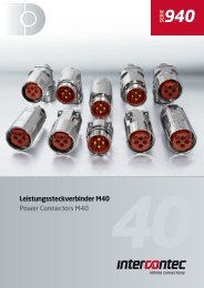
overview of <strong>TM</strong> socket-outlets with mechanical interlockWall-mounting, withsingle boxFor assembly insingle or multiple boxesoverview32A / 63A 16A<strong>TM</strong>...IT16A<strong>TM</strong>...SIT32A / 63A 16A / 32A<strong>TM</strong>...IS<strong>TM</strong>...IS/KIS16A / 32A<strong>TM</strong>...SIS/KSIS32A / 63A 16A / 32A<strong>TM</strong>...IR<strong>TM</strong>...IR/KIR16A / 32A<strong>TM</strong>...SIR/KSIR32A / 63A 16A / 32A<strong>TM</strong>...SP<strong>TM</strong>...SP/KSP16A / 32A<strong>TM</strong>...SSP/KSSP<strong>TM</strong>...T1With transformer<strong>TM</strong>...ST1With transformer<strong>TM</strong>...K..= 32A socket-outlets with 255 x 114 mm fixing base42
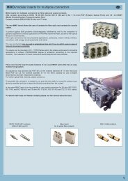
overview of <strong>TM</strong> interlocked socket-outlets and accessories for group mounting51214471113156101239overview18817162120A192422231 = <strong>TM</strong> 1145 TB (page 58)2 = <strong>TM</strong> 1456 TB (page 58)3 = <strong>TM</strong> TXT (page 58)4 = <strong>TM</strong> 1114 DB (page 60)5 = <strong>TM</strong> 1414 DB (page 60)6 = <strong>TM</strong> 1114 GB (page 61)7 = <strong>TM</strong> 1414 GB (page 61)8 = <strong>TM</strong> 1125 CS (page 62)9 = <strong>TM</strong> 2344 T2 (page 62)10 = <strong>TM</strong> 3444 T3 (page 62)11 = <strong>TM</strong> 1125 P (page 63)12 = <strong>TM</strong> 2318 P2 (page 63)13 = <strong>TM</strong> 2318 R2 (page 63)14 = <strong>TM</strong> 3418 P3 (page 63)15 = <strong>TM</strong> 3418 R3 (page 63)<strong>TM</strong> accessories16 = <strong>TM</strong> 2314 DB (page 60)17 = <strong>TM</strong> 2614 DB (page 60)18 = <strong>TM</strong> 2914 DB (page 60)19 = <strong>TM</strong> 2314 GB (page 61)20 = <strong>TM</strong> 2614 GB (page 61)21 = <strong>TM</strong> 2914 GB (page 61)22 = <strong>TM</strong> 2345 DT (page 58)23 = <strong>TM</strong> 2656 DT (page 59)24 = <strong>TM</strong> 2956 DT (page 59)LegendThe list above shows all the possible combinations of socket-outlets, back plates and enclosures that can be used to configure distribution systems.The coloured point near to the socket-outlets indicates their size, while the arrows (in the matching colour) indicate the assembly options.A = <strong>Socket</strong>-outlets with 255 x 114 mm fixing baseB = <strong>Socket</strong>-outlets with 370 x 144 mm fixing baseAB43
<strong>TM</strong>.. IT interlocked switched socket-outlets with fuse-carrier for screw-type fuses● Compliant with EN 60309 -1 and -2● Enclosures in insulating self-extinguishing thermoplasticmaterial MIL.BOX ® , printed with BC-MUL ® ,RAL 7012 grey● Inserts in insulating self-extinguishing thermoplasticmaterial, RAL 7035 grey● <strong>Socket</strong>-outlets with bayonet fastening cover● Factory installed internal wiring● Cable entry with drilling template● “Zeta” switch with I th = 32A rating (in air) and I the =32A (in enclosure) for 16A and 32A socket-outlets● Mechanical interlock that prevents:the switch from being turned on without the pluginserted and the plug from being removed while theswitch is on● Knob lockable in positions O and I● Compartment with plug-type fuse carrier (fuses notsupplied) and inspection panel openable only whenthe switch is off● q With Italian Quality Mark16AIP66/IP67 degree of protection<strong>TM</strong>..ITPoles Frequency Voltage Earthing contact Part No. ColourHz V position h2P+m 50 and 60 100 - 130 4 <strong>TM</strong> 1643 IT q50 and 60 200 - 250 6 <strong>TM</strong> 1663 IT q50 and 60 380 - 415 9 <strong>TM</strong> 1693 IT q50 and 60 480 - 500 7 <strong>TM</strong> 1673 IT q50 and 60 ins. transformer 12 <strong>TM</strong> 16123 IT q A.V.> 300 - 500 > 50 2 <strong>TM</strong> 1623 IT q * )d.c. > 50 - 250 3 <strong>TM</strong> 1633 IT q A.V.3P+m 50 and 60 100 - 130 4 <strong>TM</strong> 1644 IT q50 and 60 200 - 250 9 <strong>TM</strong> 1694 IT q50 and 60 380 - 415 6 <strong>TM</strong> 1664 IT q60 440 - 460 11 <strong>TM</strong> 16114 IT q50 and 60 480 - 500 7 <strong>TM</strong> 1674 IT q50 380 3 <strong>TM</strong> 1634 IT q60 440 3 <strong>TM</strong> 1634 IT q100 - 300 > 50 10 <strong>TM</strong> 16104 IT q * )> 300 - 500 > 50 2 <strong>TM</strong> 1624 IT q * ) )3P+N+m 50 and 60 57/100 - 75/130 4 <strong>TM</strong> 1645 IT q50 and 60 120/208 - 144/250 9 <strong>TM</strong> 1695 IT q50 and 60 200/346 - 240/415 6 <strong>TM</strong> 1665 IT q50 and 60 277/480 - 288/500 7 <strong>TM</strong> 1675 IT q60 250/440 - 265/460 11 <strong>TM</strong> 16115 IT q50 220/380 3 <strong>TM</strong> 1635 IT q60 250/440 3 <strong>TM</strong> 1635 IT q> 300 - 500 > 50 2 <strong>TM</strong> 1625 IT q * ) )LegendA.V. = Colour according to voltage*) Green may be used together with the colour of theoperating range for frequencies above 60 Hz and upto a maximum of 500 HzDimensions in mmCenter for holeRated Maximum Fuse carriercurrent operating typesocket part current16A 16A E16 - 25A-500V255 B114 A205Ø 597Poles A B2P + m 133 2763P + m 135 2763P+N+m 140 277Dimensions indicated are not binding and may bechanged without prior notice.44
<strong>TM</strong>.. IT interlocked switched socket-outlets with fuse-carrier for screw-type fuses● Compliant with EN 60309 -1 and -2● Enclosures in insulating self-extinguishing thermoplasticmaterial MIL.BOX ® , printed with BC-MUL ® ,RAL 7012 grey● Inserts in insulating self-extinguishing thermoplasticmaterial, RAL 7035 (32A) grey and white (63A)● <strong>Socket</strong>-outlets with bayonet fastening cover● 63A types with pilot contact● Factory installed internal wiring● Cable entry with drilling template● “Zeta” switch I th = 80A (in air) and I the = 63A (inenclosure) for 32A and 63A socket-outlets● Mechanical interlock that prevents:the switch from being turned on without the pluginserted and the plug from being removed while theswitch is on● Knob lockable in positions O and I● Compartment with plug-type fuse carrier (fuses notsupplied) and inspection panel openable only whenthe switch is off● q With Italian Quality Mark32AIP66/IP67 degree of protection63AIP66/IP67 degree of protectionPoles Frequency Voltage Earthing contact Part No. Colour Part No. ColourHz V position h2P+m 50 and 60 100 - 130 4 <strong>TM</strong> 3243 IT q <strong>TM</strong> 6343 IT q50 and 60 200 - 250 6 <strong>TM</strong> 3263 IT q <strong>TM</strong> 6363 IT q50 and 60 380 - 415 9 <strong>TM</strong> 3293 IT q <strong>TM</strong> 6393 IT q50 and 60 480 - 500 7 <strong>TM</strong> 3273 IT q <strong>TM</strong> 6373 IT q50 and 60 ins. transformer 12 <strong>TM</strong> 32123 IT q A.V. <strong>TM</strong> 63123 IT q A.V.> 300 - 500 > 50 2 <strong>TM</strong> 3223 IT q * )d.c. > 50 - 250 3 <strong>TM</strong> 3233 IT q A.V.<strong>TM</strong>..IT3P+m 50 and 60 100 - 130 4 <strong>TM</strong> 3244 IT q <strong>TM</strong> 6344 IT q50 and 60 200 - 250 9 <strong>TM</strong> 3294 IT q <strong>TM</strong> 6394 IT q50 and 60 380 - 415 6 <strong>TM</strong> 3264 IT q <strong>TM</strong> 6364 IT q60 440 - 460 11 <strong>TM</strong> 32114 IT q <strong>TM</strong> 63114 IT q50 and 60 480 - 500 7 <strong>TM</strong> 3274 IT q <strong>TM</strong> 6374 IT q50 380 3 <strong>TM</strong> 3234 IT q60 440 3 <strong>TM</strong> 3234 IT q100 - 300 > 50 10 <strong>TM</strong> 32104 IT q * )> 300 - 500 > 50 2 <strong>TM</strong> 3224 IT q * )3P+N+m 50 and 60 57/100 - 75/130 4 <strong>TM</strong> 3245 IT q <strong>TM</strong> 6345 IT q50 and 60 120/208 - 144/250 9 <strong>TM</strong> 3295 IT q <strong>TM</strong> 6395 IT q50 and 60 200/346 - 240/415 6 <strong>TM</strong> 3265 IT q <strong>TM</strong> 6365 IT q50 and 60 277/480 - 288/500 7 <strong>TM</strong> 3275 IT q <strong>TM</strong> 6375 IT q60 250/440 - 265/460 11 <strong>TM</strong> 32115 IT q <strong>TM</strong> 63115 IT q50 220/380 3 <strong>TM</strong> 3235 IT q60 250/440 3 <strong>TM</strong> 3235 IT q> 300 - 500 > 50 2 <strong>TM</strong> 3225 IT q * )LegendA.V. = Colour according to voltage*) Green may be used together with the colour of theoperating range for frequencies above 60 Hz and upto a maximum of 500 HzDimensions in mmCenter for holeDimensions in mmCenter for holeRatedcurrent32A63AFuse carriertypeE33 - DIII - 35A-500VE33 - DIII - 63A-500V370 398370 415144 A144 178Ø 5320Poles A2P + m 1623P + m 1623P+N+m 169Ø 5320Dimensions indicated are not binding and may bechanged without prior notice.12712745
<strong>TM</strong>.. IS/KIS interlocked socket-outlets and sectionable fuse carrier● Compliant with EN 60309 -1 and -2● Enclosures in insulating self-extinguishing thermoplasticmaterial MIL.BOX ® , printed with BC-MUL ® ,RAL 7012 grey● Inserts in insulating self-extinguishing thermoplasticmaterial, RAL 7035 grey● <strong>Socket</strong>-outlets with bayonet fastening cover● Factory installed internal wiring● Cable entry with drilling template● “Zeta” switch with I th = 32A rating for 16A and 32Asocket-outlets● Mechanical interlock that prevents:the switch from being turned on without the pluginserted and the plug from being removed while theswitch is on● Knob lockable in positions O and I● Compartment with sectionable fuse carrier (fusesnot supplied) and inspection panel openable onlywhen the switch is off● q With Italian Quality Mark16AIP66/IP67 degree of protection32AIP66/IP67 degree of protection<strong>TM</strong>..IS/KISPoles Frequency Voltage Earthing contact Part No. Colour Part No. ColourHz V position h2P+m 50 and 60 100 - 130 4 <strong>TM</strong> 1643 IS q <strong>TM</strong> 3243KIS q50 and 60 200 - 250 6 <strong>TM</strong> 1663 IS q <strong>TM</strong> 3263KIS q50 and 60 380 - 415 9 <strong>TM</strong> 1693 IS q <strong>TM</strong> 3293KIS q50 and 60 480 - 500 7 <strong>TM</strong> 1673 IS q50 and 60 ins. transformer 12 <strong>TM</strong> 16123 IS q A.V. <strong>TM</strong> 32123KIS q A.V.> 300 - 500 > 50 2 <strong>TM</strong> 1623 IS q * ) <strong>TM</strong> 3223KIS q (up to 400V) * )d.c. > 50 - 250 3 <strong>TM</strong> 1633 IS q A.V. <strong>TM</strong> 3233KIS q A.V.3P+m 50 and 60 100 - 130 4 <strong>TM</strong> 1644 IS q <strong>TM</strong> 3244KIS q50 and 60 200 - 250 9 <strong>TM</strong> 1694 IS q <strong>TM</strong> 3294KIS q50 and 60 380 - 415 6 <strong>TM</strong> 1664 IS q <strong>TM</strong> 3264KIS q60 440 - 460 11 <strong>TM</strong> 16114 IS q50 and 60 480 - 500 7 <strong>TM</strong> 1674 IS q50 380 3 <strong>TM</strong> 1634 IS q <strong>TM</strong> 3234KIS q60 440 3 <strong>TM</strong> 1634 IS q100 - 300 > 50 10 <strong>TM</strong> 16104 IS q * ) <strong>TM</strong> 32104KIS q (up to 400V) * )> 300 - 500 > 50 2 <strong>TM</strong> 1624 IS q * ) <strong>TM</strong> 3224KIS q (up to 400V) * )3P+N+m 50 and 60 57/100 - 75/130 4 <strong>TM</strong> 1645 IS q <strong>TM</strong> 3245KIS q50 and 60 120/208 - 144/250 9 <strong>TM</strong> 1695 IS q <strong>TM</strong> 3295KIS q50 and 60 200/346 - 240/415 6 <strong>TM</strong> 1665 IS q <strong>TM</strong> 3265KIS q50 and 60 277/480 - 288/500 7 <strong>TM</strong> 1675 IS q60 250/440 - 265/460 11 <strong>TM</strong> 16115 IS q50 220/380 3 <strong>TM</strong> 1635 IS q <strong>TM</strong> 3235KIS q60 250/440 3 <strong>TM</strong> 1635 IS q> 300 - 500 > 50 2 <strong>TM</strong> 1625 IS q * ) <strong>TM</strong> 3225KIS q (up to 400V) * )LegendA.V. = Colour according to voltage*) Green may be used together with the colour of theoperating range for frequencies above 60 Hz and upto a maximum of 500 HzDimensions in mmCenter for holeDimensions in mmCenter for holeRated Maximum Fuse carriercurrent operating typesocket part current16A 16A 10 x 3832A 32A 10 x 38255 B255 285114 A114 A205205Ø 597Poles A B2P + m 133 2763P + m 135 2763P+N+m 140 277Ø 597Poles A2P + m 1463P + m 1463P+N+m 151Dimensions indicated are not binding and may bechanged without prior notice.46
<strong>TM</strong>.. IS interlocked socket-outlets and sectionable fuse carrier● Compliant with EN 60309 -1 and -2● Enclosures in insulating self-extinguishing thermoplasticmaterial MIL.BOX ® , printed with BC-MUL ® ,RAL 7012 grey● Inserts in insulating self-extinguishing thermoplasticmaterial, RAL 7035 (32A) grey and white (63A)● <strong>Socket</strong>-outlets with bayonet fastening cover● 63A types with pilot contact● Factory installed internal wiring● Cable entry with drilling template● “Zeta” switch I th = 80A (in air) and I the = 63A (inenclosure) for 32A and 63A socket-outlets● Mechanical interlock that prevents:the switch from being turned on without the pluginserted and the plug from being removed while theswitch is on● Knob lockable in positions O and I● Compartment with sectionable fuse carrier (fusesnot supplied) and inspection panel openable onlywhen the switch is off● q With Italian Quality Mark32AIP66/IP67 degree of protection63AIP66/IP67 degree of protectionPoles Frequency Voltage Earthing contact Part No. Colour Part No. ColourHz V position h2P+m 50 and 60 100 - 130 4 <strong>TM</strong> 3243 IS q <strong>TM</strong> 6343 IS q50 and 60 200 - 250 6 <strong>TM</strong> 3263 IS q <strong>TM</strong> 6363 IS q50 and 60 380 - 415 9 <strong>TM</strong> 3293 IS q <strong>TM</strong> 6393 IS q50 and 60 480 - 500 7 <strong>TM</strong> 3273 IS q <strong>TM</strong> 6373 IS q50 and 60 ins. transformer 12 <strong>TM</strong> 32123 IS q A.V. <strong>TM</strong> 63123 IS q A.V.> 300 - 500 > 50 2 <strong>TM</strong> 3223 IS q * )d.c. > 50 - 250 3 <strong>TM</strong> 3233 IS q A.V.<strong>TM</strong>..IS3P+m 50 and 60 100 - 130 4 <strong>TM</strong> 3244 IS q <strong>TM</strong> 6344 IS q50 and 60 200 - 250 9 <strong>TM</strong> 3294 IS q <strong>TM</strong> 6394 IS q50 and 60 380 - 415 6 <strong>TM</strong> 3264 IS q <strong>TM</strong> 6364 IS q60 440 - 460 11 <strong>TM</strong> 32114 IS q <strong>TM</strong> 63114 IS q50 and 60 480 - 500 7 <strong>TM</strong> 3274 IS q <strong>TM</strong> 6374 IS q50 380 3 <strong>TM</strong> 3234 IS q60 440 3 <strong>TM</strong> 3234 IS q100 - 300 > 50 10 <strong>TM</strong> 32104 IS q * )> 300 - 500 > 50 2 <strong>TM</strong> 3224 IS q * )3P+N+m 50 and 60 57/100 - 75/130 4 <strong>TM</strong> 3245 IS q <strong>TM</strong> 6345 IS q50 and 60 120/208 - 144/250 9 <strong>TM</strong> 3295 IS q <strong>TM</strong> 6395 IS q50 and 60 200/346 - 240/415 6 <strong>TM</strong> 3265 IS q <strong>TM</strong> 6365 IS q50 and 60 277/480 - 288/500 7 <strong>TM</strong> 3275 IS q <strong>TM</strong> 6375 IS q60 250/440 - 265/460 11 <strong>TM</strong> 32115 IS q <strong>TM</strong> 63115 IS q50 220/380 3 <strong>TM</strong> 3235 IS q60 250/440 3 <strong>TM</strong> 3235 IS q> 300 - 500 > 50 2 <strong>TM</strong> 3225 IS q * )LegendA.V. = Colour according to voltage*) Green may be used together with the colour of theoperating range for frequencies above 60 Hz and upto a maximum of 500 HzDimensions in mmCenter for holeDimensions in mmCenter for holeRated Fuse carriercurrent type32A 14 x 5163A 22 x 58370 398370 415144 A144 178Ø 5320Poles A2P + m 1623P + m 1623P+N+m 169Ø 5320Dimensions indicated are not binding and may bechanged without prior notice.12712747
<strong>TM</strong>.. IR/KIR interlocked socket-outlets with compartment for modular units● Compliant with EN 60309 -1 and -2● Enclosures in insulating self-extinguishing thermoplasticmaterial MIL.BOX ® , printed with BC-MUL ® ,RAL 7012 grey● Inserts in insulating self-extinguishing thermoplasticmaterial, RAL 7035 grey● <strong>Socket</strong>-outlets with bayonet fastening cover● Factory installed internal wiring● Cable entry with drilling template● “Zeta” switch with I th = 32A rating for 16A and 32Asocket-outlets● Mechanical interlock that prevents:the switch from being turned on without the pluginserted and the plug from being removed while theswitch is on● Knob lockable in positions O and I● Compartment for modular units with DIN-rail EN60715 (CEI 17-78) TH 35-7,5 and inspection panelthat can be opened only when the switch is off● q With Italian Quality Mark16AIP66/IP67 degree of protection32AIP66/IP67 degree of protection<strong>TM</strong>..IR/KIRPoles Frequency Voltage Earthing contact Part No. Colour Part No. ColourHz V position h2P+m 50 and 60 100 - 130 4 <strong>TM</strong> 1643 IR q <strong>TM</strong> 3243KIR q50 and 60 200 - 250 6 <strong>TM</strong> 1663 IR q <strong>TM</strong> 3263KIR q50 and 60 380 - 415 9 <strong>TM</strong> 1693 IR q <strong>TM</strong> 3293KIR q50 and 60 480 - 500 7 <strong>TM</strong> 1673 IR q <strong>TM</strong> 3273KIR q50 and 60 ins. transformer 12 <strong>TM</strong> 16123 IR q A.V. <strong>TM</strong> 32123KIR q A.V.> 300 - 500 > 50 2 <strong>TM</strong> 1623 IR q * ) <strong>TM</strong> 3223KIR q * )d.c. > 50 - 250 3 <strong>TM</strong> 1633 IR q A.V. <strong>TM</strong> 3233KIR q A.V.3P+m 50 and 60 100 - 130 4 <strong>TM</strong> 1644 IR q <strong>TM</strong> 3244KIR q50 and 60 200 - 250 9 <strong>TM</strong> 1694 IR q <strong>TM</strong> 3294KIR q50 and 60 380 - 415 6 <strong>TM</strong> 1664 IR q <strong>TM</strong> 3264KIR q60 440 - 460 11 <strong>TM</strong> 16114 IR q <strong>TM</strong> 32114KIR q50 and 60 480 - 500 7 <strong>TM</strong> 1674 IR q <strong>TM</strong> 3274KIR q50 380 3 <strong>TM</strong> 1634 IR q <strong>TM</strong> 3234KIR q60 440 3 <strong>TM</strong> 1634 IR q <strong>TM</strong> 3234KIR q100 - 300 > 50 10 <strong>TM</strong> 16104 IR q * ) <strong>TM</strong> 32104KIR q * )> 300 - 500 > 50 2 <strong>TM</strong> 1624 IR q * ) <strong>TM</strong> 3224KIR q * )3P+N+m 50 and 60 57/100 - 75/130 4 <strong>TM</strong> 1645 IR q <strong>TM</strong> 3245KIR q50 and 60 120/208 - 144/250 9 <strong>TM</strong> 1695 IR q <strong>TM</strong> 3295KIR q50 and 60 200/346 - 240/415 6 <strong>TM</strong> 1665 IR q <strong>TM</strong> 3265KIR q50 and 60 277/480 - 288/500 7 <strong>TM</strong> 1675 IR q <strong>TM</strong> 3275KIR q60 250/440 - 265/460 11 <strong>TM</strong> 16115 IR q <strong>TM</strong> 32115KIR q50 220/380 3 <strong>TM</strong> 1635 IR q <strong>TM</strong> 3235KIR q60 250/440 3 <strong>TM</strong> 1635 IR q <strong>TM</strong> 3235KIR q> 300 - 500 > 50 2 <strong>TM</strong> 1625 IR q * ) <strong>TM</strong> 3225KIR q * )LegendA.V. = Colour according to voltage*) Green may be used together with the colour of theoperating range for frequencies above 60 Hz and upto a maximum of 500 HzDimensions in mmCenter for holeDimensions in mmCenter for holeRated of Maximum operating N. of modulessocket part current DIN-rail16A 16A 4.532A 32A 4.5255 B255 285114 A114 A205205Ø 597Poles A B2P + m 133 2763P + m 135 2763P+N+m 140 277Ø 597Poles A2P + m 1463P + m 1463P+N+m 151Dimensions indicated are not binding and may bechanged without prior notice.48
<strong>TM</strong>.. IR interlocked socket-outlets with compartment for modular units● Compliant with EN 60309 -1 and -2● Enclosures in insulating self-extinguishing thermoplasticmaterial MIL.BOX ® , printed with BC-MUL ® ,RAL 7012 grey● Inserts in insulating self-extinguishing thermoplasticmaterial, RAL 7035 (32A) grey and white (63A)● <strong>Socket</strong>-outlets with bayonet fastening cover● 63A types with pilot contact● Factory installed internal wiring● Cable entry with drilling template● “Zeta” switch I th = 80A (in air) and I the = 63A (inenclosure) for 32A and 63A socket-outlets● Mechanical interlock that prevents:the switch from being turned on without the pluginserted and the plug from being removed while theswitch is on● Knob lockable in positions O and I● Compartment for modular units with DIN-rail EN60715 (CEI 17-78) TH 35-7,5 and inspection panelthat can be opened only when the switch is off● q With Italian Quality Mark32AIP66/IP67 degree of protection63AIP66/IP67 degree of protectionPoles Frequency Voltage Earthing contact Part No. Colour Part No. ColourHz V position h2P+m 50 and 60 100 - 130 4 <strong>TM</strong> 3243 IR q <strong>TM</strong> 6343 IR q50 and 60 200 - 250 6 <strong>TM</strong> 3263 IR q <strong>TM</strong> 6363 IR q50 and 60 380 - 415 9 <strong>TM</strong> 3293 IR q <strong>TM</strong> 6393 IR q50 and 60 480 - 500 7 <strong>TM</strong> 3273 IR q <strong>TM</strong> 6373 IR q50 and 60 ins. transformer 12 <strong>TM</strong> 32123 IR q A.V. <strong>TM</strong> 63123 IR q A.V.> 300 - 500 > 50 2 <strong>TM</strong> 3223 IR q * )d.c. > 50 - 250 3 <strong>TM</strong> 3233 IR q A.V.<strong>TM</strong>..IR3P+m 50 and 60 100 - 130 4 <strong>TM</strong> 3244 IR q <strong>TM</strong> 6344 IR q50 and 60 200 - 250 9 <strong>TM</strong> 3294 IR q <strong>TM</strong> 6394 IR q50 and 60 380 - 415 6 <strong>TM</strong> 3264 IR q <strong>TM</strong> 6364 IR q60 440 - 460 11 <strong>TM</strong> 32114 IR q <strong>TM</strong> 63114 IR q50 and 60 480 - 500 7 <strong>TM</strong> 3274 IR q <strong>TM</strong> 6374 IR q50 380 3 <strong>TM</strong> 3234 IR q60 440 3 <strong>TM</strong> 3234 IR q100 - 300 > 50 10 <strong>TM</strong> 32104 IR q * )> 300 - 500 > 50 2 <strong>TM</strong> 3224 IR q * )3P+N+m 50 and 60 57/100 - 75/130 4 <strong>TM</strong> 3245 IR q <strong>TM</strong> 6345 IR q50 and 60 120/208 - 144/250 9 <strong>TM</strong> 3295 IR q <strong>TM</strong> 6395 IR q50 and 60 200/346 - 240/415 6 <strong>TM</strong> 3265 IR q <strong>TM</strong> 6365 IR q50 and 60 277/480 - 288/500 7 <strong>TM</strong> 3275 IR q <strong>TM</strong> 6375 IR q60 250/440 - 265/460 11 <strong>TM</strong> 32115 IR q <strong>TM</strong> 63115 IR q50 220/380 3 <strong>TM</strong> 3235 IR q60 250/440 3 <strong>TM</strong> 3235 IR q> 300 - 500 > 50 2 <strong>TM</strong> 3225 IR q * )LegendA.V. = Colour according to voltage*) Green may be used together with the colour of theoperating range for frequencies above 60 Hz and upto a maximum of 500 HzDimensions in mmCenter for holeDimensions in mmCenter for holeRated of N. of modulessocket part DIN-rail32A 663A 6370 398370 415144 A144 178Ø 5320Poles A2P + m 1623P + m 1623P+N+m 169Ø 5320Dimensions indicated are not binding and may bechanged without prior notice.12712749
<strong>TM</strong>.. SP/KSP interlocked socket-outlets● Compliant with EN 60309 -1 and -2● Enclosures in insulating self-extinguishing thermoplasticmaterial MIL.BOX ® , printed with BC-MUL ® ,RAL 7012 grey● Inserts in insulating self-extinguishing thermoplasticmaterial, RAL 7035 grey● <strong>Socket</strong>-outlets with bayonet fastening cover● Factory installed internal wiring● Cable entry with drilling template● “Zeta” switch with I th = 32A rating for 16A and 32Asocket-outlets● Mechanical interlock that prevents:the switch from being turned on without the pluginserted and the plug from being removed while theswitch is on● Knob lockable in positions O and I● q With Italian Quality Mark16AIP66/IP67 degree of protection32AIP66/IP67 degree of protection<strong>TM</strong>..SP/KSPPoles Frequency Voltage Earthing contact Part No. Colour Part No. ColourHz V position h2P+m 50 and 60 100 - 130 4 <strong>TM</strong> 1643 SP q <strong>TM</strong> 3243KSP q50 and 60 200 - 250 6 <strong>TM</strong> 1663 SP q <strong>TM</strong> 3263KSP q50 and 60 380 - 415 9 <strong>TM</strong> 1693 SP q <strong>TM</strong> 3293KSP q50 and 60 480 - 500 7 <strong>TM</strong> 1673 SP q <strong>TM</strong> 3273KSP q50 and 60 ins. transformer 12 <strong>TM</strong> 16123 SP q A.V. <strong>TM</strong> 32123KSP q A.V.> 300 - 500 > 50 2 <strong>TM</strong> 1623 SP q * ) <strong>TM</strong> 3223KSP q * )d.c. > 50 - 250 3 <strong>TM</strong> 1633 SP q A.V. <strong>TM</strong> 3233KSP q A.V.3P+m 50 and 60 100 - 130 4 <strong>TM</strong> 1644 SP q <strong>TM</strong> 3244KSP q50 and 60 200 - 250 9 <strong>TM</strong> 1694 SP q <strong>TM</strong> 3294KSP q50 and 60 380 - 415 6 <strong>TM</strong> 1664 SP q <strong>TM</strong> 3264KSP q60 440 - 460 11 <strong>TM</strong> 16114 SP q <strong>TM</strong> 32114KSP q50 and 60 480 - 500 7 <strong>TM</strong> 1674 SP q <strong>TM</strong> 3274KSP q50 380 3 <strong>TM</strong> 1634 SP q <strong>TM</strong> 3234KSP q60 440 3 <strong>TM</strong> 1634 SP q <strong>TM</strong> 3234KSP q100 - 300 > 50 10 <strong>TM</strong> 16104 SP q * ) <strong>TM</strong> 32104KSP q * )> 300 - 500 > 50 2 <strong>TM</strong> 1624 SP q * ) <strong>TM</strong> 3224KSP q * )3P+N+m 50 and 60 57/100 - 75/130 4 <strong>TM</strong> 1645 SP q <strong>TM</strong> 3245KSP q50 and 60 120/208 - 144/250 9 <strong>TM</strong> 1695 SP q <strong>TM</strong> 3295KSP q50 and 60 200/346 - 240/415 6 <strong>TM</strong> 1665 SP q <strong>TM</strong> 3265KSP q50 and 60 277/480 - 288/500 7 <strong>TM</strong> 1675 SP q <strong>TM</strong> 3275KSP q60 250/440 - 265/460 11 <strong>TM</strong> 16115 SP q <strong>TM</strong> 32115KSP q50 220/380 3 <strong>TM</strong> 1635 SP q <strong>TM</strong> 3235KSP q60 250/440 3 <strong>TM</strong> 1635 SP q <strong>TM</strong> 3235KSP q> 300 - 500 > 50 2 <strong>TM</strong> 1625 SP q * ) <strong>TM</strong> 3225KSP q * )LegendA.V. = Colour according to voltage*) Green may be used together with the colour of theoperating range for frequencies above 60 Hz and upto a maximum of 500 HzDimensions in mmCenter for holeDimensions in mmCenter for hole255 B255 285114 A114 A205205Ø 597Poles A B2P + m 133 2763P + m 135 2763P+N+m 140 277Ø 597Poles A2P + m 1463P + m 1463P+N+m 151Dimensions indicated are not binding and may bechanged without prior notice.50
<strong>TM</strong>.. SP interlocked socket-outlets● Compliant with EN 60309 -1 and -2● Enclosures in insulating self-extinguishing thermoplasticmaterial MIL.BOX ® , printed with BC-MUL ® ,RAL 7012 grey● Inserts in insulating self-extinguishing thermoplasticmaterial, RAL 7035 (32A) grey and white (63A)● <strong>Socket</strong>-outlets with bayonet fastening cover● 63A types with pilot contact● Factory installed internal wiring● Cable entry with drilling template● “Zeta” switch I th = 80A (in air) and I the = 63A (inenclosure) for 32A and 63A socket-outlets● Mechanical interlock that prevents:the switch from being turned on without the pluginserted and the plug from being removed while theswitch is on● Knob lockable in positions O and I● q With Italian Quality Mark32AIP66/IP67 degree of protection63AIP66/IP67 degree of protectionPoles Frequency Voltage Earthing contact Part No. Colour Part No. ColourHz V position h2P+m 50 and 60 100 - 130 4 <strong>TM</strong> 3243 SP q <strong>TM</strong> 6343 SP q50 and 60 200 - 250 6 <strong>TM</strong> 3263 SP q <strong>TM</strong> 6363 SP q50 and 60 380 - 415 9 <strong>TM</strong> 3293 SP q <strong>TM</strong> 6393 SP q50 and 60 480 - 500 7 <strong>TM</strong> 3273 SP q <strong>TM</strong> 6373 SP q50 and 60 ins. transformer 12 <strong>TM</strong> 32123 SP q A.V. <strong>TM</strong> 63123 SP q A.V.> 300 - 500 > 50 2 <strong>TM</strong> 3223 SP q * )d.c. > 50 - 250 3 <strong>TM</strong> 3233 SP q A.V.<strong>TM</strong>..SP3P+m 50 and 60 100 - 130 4 <strong>TM</strong> 3244 SP q <strong>TM</strong> 6344 SP q50 and 60 200 - 250 9 <strong>TM</strong> 3294 SP q <strong>TM</strong> 6394 SP q50 and 60 380 - 415 6 <strong>TM</strong> 3264 SP q <strong>TM</strong> 6364 SP q60 440 - 460 11 <strong>TM</strong> 32114 SP q <strong>TM</strong> 63114 SP q50 and 60 480 - 500 7 <strong>TM</strong> 3274 SP q <strong>TM</strong> 6374 SP q50 380 3 <strong>TM</strong> 3234 SP q60 440 3 <strong>TM</strong> 3234 SP q100 - 300 > 50 10 <strong>TM</strong> 32104 SP q * )> 300 - 500 > 50 2 <strong>TM</strong> 3224 SP q * )3P+N+m 50 and 60 57/100 - 75/130 4 <strong>TM</strong> 3245 SP q <strong>TM</strong> 6345 SP q50 and 60 120/208 - 144/250 9 <strong>TM</strong> 3295 SP q <strong>TM</strong> 6395 SP q50 and 60 200/346 - 240/415 6 <strong>TM</strong> 3265 SP q <strong>TM</strong> 6365 SP q50 and 60 277/480 - 288/500 7 <strong>TM</strong> 3275 SP q <strong>TM</strong> 6375 SP q60 250/440 - 265/460 11 <strong>TM</strong> 32115 SP q <strong>TM</strong> 63115 SP q50 220/380 3 <strong>TM</strong> 3235 SP q60 250/440 3 <strong>TM</strong> 3235 SP q> 300 - 500 > 50 2 <strong>TM</strong> 3225 SP q * )LegendA.V. = Colour according to voltage*) Green may be used together with the colour of theoperating range for frequencies above 60 Hz and upto a maximum of 500 HzDimensions in mmCenter for holeDimensions in mmCenter for hole370 398370 415144 A144 178Ø 5320Poles A2P + m 1623P + m 1623P+N+m 169Ø 5320Dimensions indicated are not binding and may bechanged without prior notice.12712751
<strong>TM</strong>.. SIT interlocked socket-switches, with plug-type fuse carrier and without base box● Compliant with EN 60309 -1 and -2● Enclosures in insulating self-extinguishing thermoplasticmaterial MIL.BOX ® , printed with BC-MUL ® ,RAL 7012 grey● Inserts in insulating self-extinguishing thermoplasticmaterial, RAL 7035 grey● <strong>Socket</strong>-outlets with bayonet fastening cover● Factory installed internal wiring● “Zeta” switch with I th = 32A rating (in air) and I the =32A (in enclosure) for 16A and 32A socket-outlets● Mechanical interlock that prevents:the switch from being turned on without the pluginserted and the plug from being removed while theswitch is on● Knob lockable in positions O and I● Compartment with plug-type fuse carrier (fuses notsupplied) and inspection panel openable only whenthe switch is off● q With Italian Quality Mark16AIP66/IP67 degree of protection<strong>TM</strong>..SITPoles Frequency Voltage Earthing contact Part No. ColourHz V position h2P+m 50 and 60 100 - 130 4 <strong>TM</strong> 1643 SIT q50 and 60 200 - 250 6 <strong>TM</strong> 1663 SIT q50 and 60 380 - 415 9 <strong>TM</strong> 1693 SIT q50 and 60 480 - 500 7 <strong>TM</strong> 1673 SIT q50 and 60 ins. transformer 12 <strong>TM</strong> 16123 SIT q A.V.> 300 - 500 > 50 2 <strong>TM</strong> 1623 SIT q * )d.c. > 50 - 250 3 <strong>TM</strong> 1633 SIT q A.V.3P+m 50 and 60 100 - 130 4 <strong>TM</strong> 1644 SIT q50 and 60 200 - 250 9 <strong>TM</strong> 1694 SIT q50 and 60 380 - 415 6 <strong>TM</strong> 1664 SIT q60 440 - 460 11 <strong>TM</strong> 16114 SIT q50 and 60 480 - 500 7 <strong>TM</strong> 1674 SIT q50 380 3 <strong>TM</strong> 1634 SIT q60 440 3 <strong>TM</strong> 1634 SIT q100 - 300 > 50 10 <strong>TM</strong> 16104 SIT q * )> 300 - 500 > 50 2 <strong>TM</strong> 1624 SIT q * )3P+N+m 50 and 60 57/100 - 75/130 4 <strong>TM</strong> 1645 SIT q50 and 60 120/208 - 144/250 9 <strong>TM</strong> 1695 SIT q50 and 60 200/346 - 240/415 6 <strong>TM</strong> 1665 SIT q50 and 60 277/480 - 288/500 7 <strong>TM</strong> 1675 SIT q60 250/440 - 265/460 11 <strong>TM</strong> 16115 SIT q50 220/380 3 <strong>TM</strong> 1635 SIT q60 250/440 3 <strong>TM</strong> 1635 SIT q> 300 - 500 > 50 2 <strong>TM</strong> 1625 SIT q * )LegendA.V. = Colour according to voltage*) Green may be used together with the colour of theoperating range for frequencies above 60 Hz and upto a maximum of 500 HzDimensions in mm255 BRated Maximum Fuse carriercurrent operating typesocket part current16A 16A E16 - 25A-500V114 <strong>AP</strong>oles A B2P + m 83 2763P + m 85 2763P+N+m 90 277Dimensions indicated are not binding and may bechanged without prior notice.52
<strong>TM</strong>.. SIS/KSIS interlocked socket-switches, with sectionable fuse carrier and without base box● Compliant with EN 60309 -1 and -2● Enclosures in insulating self-extinguishing thermoplasticmaterial MIL.BOX ® , printed with BC-MUL ® ,RAL 7012 grey● Inserts in insulating self-extinguishing thermoplasticmaterial, RAL 7035 grey● <strong>Socket</strong>-outlets with bayonet fastening cover● Factory installed internal wiring● “Zeta” switch with I th = 32A rating for 16A and 32Asocket-outlets● Mechanical interlock that prevents:the switch from being turned on without the pluginserted and the plug from being removed while theswitch is on● Knob lockable in positions O and I● Compartment with sectionable fuse carrier (fusesnot supplied) and inspection panel openable onlywhen the switch is off● q With Italian Quality Mark16AIP66/IP67 degree of protection32AIP66/IP67 degree of protectionPoles Frequency Voltage Earthing contact Part No. Colour Part No. ColourHz V position h2P+m 50 and 60 100 - 130 4 <strong>TM</strong> 1643 SIS q <strong>TM</strong> 3243KSIS q50 and 60 200 - 250 6 <strong>TM</strong> 1663 SIS q <strong>TM</strong> 3263KSIS q50 and 60 380 - 415 9 <strong>TM</strong> 1693 SIS q <strong>TM</strong> 3293KSIS q50 and 60 480 - 500 7 <strong>TM</strong> 1673 SIS q50 and 60 ins. transformer 12 <strong>TM</strong> 16123 SIS q A.V. <strong>TM</strong> 32123KSIS q A.V.> 300 - 500 > 50 2 <strong>TM</strong> 1623 SIS q * ) <strong>TM</strong> 3223KSIS q (up to 400V) * )d.c. > 50 - 250 3 <strong>TM</strong> 1633 SIS q A.V. <strong>TM</strong> 3233KSIS q A.V.<strong>TM</strong>..SIS/KSIS3P+m 50 and 60 100 - 130 4 <strong>TM</strong> 1644 SIS q <strong>TM</strong> 3244KSIS q50 and 60 200 - 250 9 <strong>TM</strong> 1694 SIS q <strong>TM</strong> 3294KSIS q50 and 60 380 - 415 6 <strong>TM</strong> 1664 SIS q <strong>TM</strong> 3264KSIS q60 440 - 460 11 <strong>TM</strong> 16114 SIS q50 and 60 480 - 500 7 <strong>TM</strong> 1674 SIS q50 380 3 <strong>TM</strong> 1634 SIS q <strong>TM</strong> 3234KSIS q60 440 3 <strong>TM</strong> 1634 SIS q100 - 300 > 50 10 <strong>TM</strong> 16104 SIS q * ) <strong>TM</strong> 32104KSIS q (up to 400V) * )> 300 - 500 > 50 2 <strong>TM</strong> 1624 SIS q * ) <strong>TM</strong> 3224KSIS q (up to 400V) * )3P+N+m 50 and 60 57/100 - 75/130 4 <strong>TM</strong> 1645 SIS q <strong>TM</strong> 3245KSIS q50 and 60 120/208 - 144/250 9 <strong>TM</strong> 1695 SIS q <strong>TM</strong> 3295KSIS q50 and 60 200/346 - 240/415 6 <strong>TM</strong> 1665 SIS q <strong>TM</strong> 3265KSIS q50 and 60 277/480 - 288/500 7 <strong>TM</strong> 1675 SIS q60 250/440 - 265/460 11 <strong>TM</strong> 16115 SIS q50 220/380 3 <strong>TM</strong> 1635 SIS q <strong>TM</strong> 3235KSIS q60 250/440 3 <strong>TM</strong> 1635 SIS q> 300 - 500 > 50 2 <strong>TM</strong> 1625 SIS q * ) <strong>TM</strong> 3225KSIS q (up to 400V) * )LegendA.V. = Colour according to voltage*) Green may be used together with the colour of theoperating range for frequencies above 60 Hz and upto a maximum of 500 HzDimensions in mmDimensions in mmRated Maximum Fuse carriercurrent operating typesocket part current16A 16A 10 x 3832A 32A 10 x 38255 B255 285114 A114 <strong>AP</strong>oles A B2P + m 83 2763P + m 85 2763P+N+m 90 277Poles A2P + m 963P + m 963P+N+m 101Dimensions indicated are not binding and may bechanged without prior notice.53
<strong>TM</strong>.. SIR/KSIR interlocked socket-outlets, with compartment for modular units, without base box● Compliant with EN 60309 -1 and -2● Enclosures in insulating self-extinguishing thermoplasticmaterial MIL.BOX ® , printed with BC-MUL ® ,RAL 7012 grey● Inserts in insulating self-extinguishing thermoplasticmaterial, RAL 7035 grey● <strong>Socket</strong>-outlets with bayonet fastening cover● Factory installed internal wiring● “Zeta” switch with I th = 32A rating for 16A and 32Asocket-outlets● Mechanical interlock that prevents:the switch from being turned on without the pluginserted and the plug from being removed while theswitch is on● Knob lockable in positions O and I● Compartment for modular units with DIN-rail EN60715 (CEI 17-78) TH 35-7,5 and inspection panelthat can be opened only when the switch is off● q With Italian Quality Mark16AIP66/IP67 degree of protection32AIP66/IP67 degree of protection<strong>TM</strong>..SIR/KSIRPoles Frequency Voltage Earthing contact Part No. Colour Part No. ColourHz V position h2P+m 50 and 60 100 - 130 4 <strong>TM</strong> 1643 SIR q <strong>TM</strong> 3243KSIR q50 and 60 200 - 250 6 <strong>TM</strong> 1663 SIR q <strong>TM</strong> 3263KSIR q50 and 60 380 - 415 9 <strong>TM</strong> 1693 SIR q <strong>TM</strong> 3293KSIR q50 and 60 480 - 500 7 <strong>TM</strong> 1673 SIR q <strong>TM</strong> 3273KSIR q50 and 60 ins. transformer 12 <strong>TM</strong> 16123 SIR q A.V. <strong>TM</strong> 32123KSIR q A.V.> 300 - 500 > 50 2 <strong>TM</strong> 1623 SIR q * ) <strong>TM</strong> 3223KSIR q * )d.c. > 50 - 250 3 <strong>TM</strong> 1633 SIR q A.V. <strong>TM</strong> 3233KSIR q A.V.3P+m 50 and 60 100 - 130 4 <strong>TM</strong> 1644 SIR q <strong>TM</strong> 3244KSIR q50 and 60 200 - 250 9 <strong>TM</strong> 1694 SIR q <strong>TM</strong> 3294KSIR q50 and 60 380 - 415 6 <strong>TM</strong> 1664 SIR q <strong>TM</strong> 3264KSIR q60 440 - 460 11 <strong>TM</strong> 16114 SIR q <strong>TM</strong> 32114KSIR q50 and 60 480 - 500 7 <strong>TM</strong> 1674 SIR q <strong>TM</strong> 3274KSIR q50 380 3 <strong>TM</strong> 1634 SIR q <strong>TM</strong> 3234KSIR q60 440 3 <strong>TM</strong> 1634 SIR q <strong>TM</strong> 3234KSIR q100 - 300 > 50 10 <strong>TM</strong> 16104 SIR q * ) <strong>TM</strong> 32104KSIR q * )> 300 - 500 > 50 2 <strong>TM</strong> 1624 SIR q * ) <strong>TM</strong> 3224KSIR q * )3P+N+m 50 and 60 57/100 - 75/130 4 <strong>TM</strong> 1645 SIR q <strong>TM</strong> 3245KSIR q50 and 60 120/208 - 144/250 9 <strong>TM</strong> 1695 SIR q <strong>TM</strong> 3295KSIR q50 and 60 200/346 - 240/415 6 <strong>TM</strong> 1665 SIR q <strong>TM</strong> 3265KSIR q50 and 60 277/480 - 288/500 7 <strong>TM</strong> 1675 SIR q <strong>TM</strong> 3275KSIR q60 250/440 - 265/460 11 <strong>TM</strong> 16115 SIR q <strong>TM</strong> 32115KSIR q50 220/380 3 <strong>TM</strong> 1635 SIR q <strong>TM</strong> 3235KSIR q60 250/440 3 <strong>TM</strong> 1635 SIR q <strong>TM</strong> 3235KSIR q> 300 - 500 > 50 2 <strong>TM</strong> 1625 SIR q * ) <strong>TM</strong> 3225KSIR q * )LegendA.V. = Colour according to voltage*) Green may be used together with the colour of theoperating range for frequencies above 60 Hz and upto a maximum of 500 HzDimensions in mmDimensions in mmRated of Maximum operating N. of modulessocket part current DIN-rail16A 16A 4.532A 32A 4.5255 B255 285114 A114 <strong>AP</strong>oles A B2P + m 83 2763P + m 85 2763P+N+m 90 277Poles A2P + m 963P + m 963P+N+m 101Dimensions indicated are not binding and may bechanged without prior notice.54
<strong>TM</strong>.. SSP/KSSP interlocked socket-outlets without base box● Compliant with EN 60309 -1 and -2● Enclosures in insulating self-extinguishing thermoplasticmaterial MIL.BOX ® , printed with BC-MUL ® ,RAL 7012 grey● Inserts in insulating self-extinguishing thermoplasticmaterial, RAL 7035 grey● <strong>Socket</strong>-outlets with bayonet fastening cover● Factory installed internal wiring● “Zeta” switch with I th = 32A rating for 16A and 32Asocket-outlets● Mechanical interlock that prevents:the switch from being turned on without the pluginserted and the plug from being removed while theswitch is on● Knob lockable in positions O and I● q With Italian Quality Mark16AIP66/IP67 degree of protection32AIP66/IP67 degree of protectionPoles Frequency Voltage Earthing contact Part No. Colour Part No. ColourHz V position h2P+m 50 and 60 100 - 130 4 <strong>TM</strong> 1643 SSP q <strong>TM</strong> 3243KSSP q50 and 60 200 - 250 6 <strong>TM</strong> 1663 SSP q <strong>TM</strong> 3263KSSP q50 and 60 380 - 415 9 <strong>TM</strong> 1693 SSP q <strong>TM</strong> 3293KSSP q50 and 60 480 - 500 7 <strong>TM</strong> 1673 SSP q <strong>TM</strong> 3273KSSP q50 and 60 ins. transformer 12 <strong>TM</strong> 16123 SSP q A.V. <strong>TM</strong> 32123KSSP q A.V.> 300 - 500 > 50 2 <strong>TM</strong> 1623 SSP q * ) <strong>TM</strong> 3223KSSP q * )d.c. > 50 - 250 3 <strong>TM</strong> 1633 SSP q A.V. <strong>TM</strong> 3233KSSP q A.V.<strong>TM</strong>..SSP/KSSP3P+m 50 and 60 100 - 130 4 <strong>TM</strong> 1644 SSP q <strong>TM</strong> 3244KSSP q50 and 60 200 - 250 9 <strong>TM</strong> 1694 SSP q <strong>TM</strong> 3294KSSP q50 and 60 380 - 415 6 <strong>TM</strong> 1664 SSP q <strong>TM</strong> 3264KSSP q60 440 - 460 11 <strong>TM</strong> 16114 SSP q <strong>TM</strong> 32114KSSP q50 and 60 480 - 500 7 <strong>TM</strong> 1674 SSP q <strong>TM</strong> 3274KSSP q50 380 3 <strong>TM</strong> 1634 SSP q <strong>TM</strong> 3234KSSP q60 440 3 <strong>TM</strong> 1634 SSP q <strong>TM</strong> 3234KSSP q100 - 300 > 50 10 <strong>TM</strong> 16104 SSP q * ) <strong>TM</strong> 32104KSSP q * )> 300 - 500 > 50 2 <strong>TM</strong> 1624 SSP q * ) <strong>TM</strong> 3224KSSP q * )3P+N+m 50 and 60 57/100 - 75/130 4 <strong>TM</strong> 1645 SSP q <strong>TM</strong> 3245KSSP q50 and 60 120/208 - 144/250 9 <strong>TM</strong> 1695 SSP q <strong>TM</strong> 3295KSSP q50 and 60 200/346 - 240/415 6 <strong>TM</strong> 1665 SSP q <strong>TM</strong> 3265KSSP q50 and 60 277/480 - 288/500 7 <strong>TM</strong> 1675 SSP q <strong>TM</strong> 3275KSSP q60 250/440 - 265/460 11 <strong>TM</strong> 16115 SSP q <strong>TM</strong> 32115KSSP q50 220/380 3 <strong>TM</strong> 1635 SSP q <strong>TM</strong> 3235KSSP q60 250/440 3 <strong>TM</strong> 1635 SSP q <strong>TM</strong> 3235KSSP q> 300 - 500 > 50 2 <strong>TM</strong> 1625 SSP q * ) <strong>TM</strong> 3225KSSP q * )LegendA.V. = Colour according to voltage*) Green may be used together with the colour of theoperating range for frequencies above 60 Hz and upto a maximum of 500 HzDimensions in mmDimensions in mm255 B255 285114 A114 <strong>AP</strong>oles A B2P + m 83 2763P + m 85 2763P+N+m 90 277Poles A2P + m 963P + m 963P+N+m 101Dimensions indicated are not binding and may bechanged without prior notice.55
<strong>TM</strong>.. T1/ST1 socket-outlets with safety transformer● Compliant with CEI EN 60309 -1 and -2● Enclosures in insulating self-extinguishing thermoplasticmaterial MIL.BOX ® , printed with BC-MUL ® ,RAL 7012 grey● Inserts in insulating self-extinguishing thermoplasticmaterial, RAL 7035 grey● <strong>Socket</strong>-outlets with bayonet fastening cover● Toroid safety transformer with self-resetting thermalprotection, 230V/24V~, forthe supply of Class III portable lamps, compliantwith EN 60742● Electric interlock with button to disconnect the primarycircuit of the transformer if the plug is off● Factory installed internal wiring● The cable entry of models with base boxrequires the drilling of holes● q With Italian Quality MarkWith base boxIP66/IP67 degree of protectionWithout base boxIP66/IP67 degree of protection<strong>TM</strong>..T1/ST1Description Part No. Colour Part No. Colour<strong>Socket</strong>-outlet with base box16A - 2P - 24V~ - 144VA - Continuous duty<strong>Socket</strong>-outlet without base box16A - 2P - 24V~ - 144VA - Continuous duty<strong>TM</strong> 16220 T1 q<strong>TM</strong> 16220 ST1 qDimensions in mmCenter for holeDimensions in mm255 277255 277114 125114 75205Ø 597Dimensions indicated are not binding and may bechanged without prior notice.56
<strong>TM</strong> complementary parts and accessories for groups● Enclosures and parts of enclosures compliant withIEC 60670 (Italian standard CEI 23-48) and withItalian draft standard CEI 23-49● In insulating self-extinguishing thermoplastic materialMIL.BOX ® , printed with BC-MUL ® , RAL 7012 grey● Plates with fixing plugs and fixing screws for socketoutlets● Boxes for modular units with sized DIN-rail EN 60715TH 35-7,5 with closing plates and fittings● q With Italian Quality Mark (CEI 23-48)Modular back platesfor the assembly of groups of socket-outlets“Small” assembled modular base for twosocket-outlets and enclosure for modular units<strong>TM</strong> groupsDescription Part No. Part No.Plates with fixing plugs- Small (115 x 415 x 30 mm) 1) <strong>TM</strong> 1145 TB- Large (145 x 532 x 30 mm) 2) <strong>TM</strong> 1456 TBFixing plugs for plates<strong>TM</strong> TXTIncludes:- 2 <strong>TM</strong> 1145 TB plates 1)- 1 <strong>TM</strong> 2314 GB box for modular unites (10.5 units)<strong>TM</strong> 2345 DT qLegendDimensions in mmDimensions in mm1) For socket-outlets with <strong>TM</strong> box, 114x255 mm2) For socket-outlets with <strong>TM</strong> box, 144x370 mm<strong>TM</strong> 1145 TB15Center for hole450420450ø 5115 18851523018120<strong>TM</strong> 1456 TB15Panel cut-out in mm420565535ø 5ø 5200145 1811515Dimensions indicated are not binding and may bechanged without prior notice.58
<strong>TM</strong> complementary parts and accessories for groups● Enclosures and parts of enclosures compliant withIEC 60670 (Italian standard CEI 23-48) and withItalian draft standard CEI 23-49● In insulating self-extinguishing thermoplastic materialMIL.BOX ® , printed with BC-MUL ® , RAL 7012 grey● Plates with fixing plugs and fixing screws for socketoutlets● Boxes for modular units, with sized DIN-rail EN 60715TH 35-7.5, closing plates, fittings and fixing screws● q With Italian Quality Mark (CEI 23-48)“Mixed” assembled modular base for twosocket-outlets and enclosure for modular units“Large” assembled modular base for twosocket-outlets and enclosure for modular unitsDescription Part No. Part No.Includes:- 1 <strong>TM</strong> 1456 TB plate 2)- 1 <strong>TM</strong> 1145 TB plate 1)- 1 <strong>TM</strong> 2614 GB box for modular unites (12 units)<strong>TM</strong> 2656 DT q<strong>TM</strong> groupsIncludes:- 2 <strong>TM</strong> 1456 TB plates 2)- 1 <strong>TM</strong> 2914 GB box for modular units (13.5 units)LegendDimensions in mm<strong>TM</strong> 2956 DT qDimensions in mm1) For socket-outlets with <strong>TM</strong> box, 114x255 mm2) For socket-outlets with <strong>TM</strong> box, 144x370 mmCenter for holeCenter for hole5655652601812029018120Panel cut-out in mmPanel cut-out in mm420535535ø 5ø 5230260Dimensions indicated are not binding and may bechanged without prior notice.59
<strong>TM</strong> complementary parts and accessories for groupsJunction boxes - IP66/IP67Junction boxes - IP66/IP67● Compliant with international standard IEC 60670(Italian standard CEI 23-48)● In insulating self-extinguishing thermoplastic materialMIL.BOX ® , printed with BC-MUL ® , RAL 7012 grey● Junction boxes suitable for the assembly of fixingplates or DIN-rail● Fixing plates in zinc-plated steel with fixing screws● Blind plug-type, fixed cover● q With Italian Quality Mark (CEI 23-48)accessoriesDescription Part No. Part No.For <strong>TM</strong> 1145 TB plate- IP66/67 degree of protection (EN 60529) <strong>TM</strong> 1114 DB qFor <strong>TM</strong> 1456 TB plate- IP66/67 degree of protection (EN 60529) <strong>TM</strong> 1414 DB qFor 2 <strong>TM</strong> 1145 TB plates- IP66/67 degree of protection (EN 60529) <strong>TM</strong> 2314 DB qFor 1 <strong>TM</strong> 1145 TB plate + 1 <strong>TM</strong> 1456 TB plate- IP66/67 degree of protection (EN 60529) <strong>TM</strong> 2614 DB qFor 2 <strong>TM</strong> 1456 TB plates- IP66/67 degree of protection (EN 60529) <strong>TM</strong> 2914 DB qDimensions in mm<strong>TM</strong> 1114 DB<strong>TM</strong> ... DBCenter for holeCenter for holes144Center forhole144115Center forhole94.5CenterA forhole94.5ø 594ø 59498B<strong>TM</strong> 1414 DB144Centerfor holeCenter for holePart No. A B<strong>TM</strong> 2314 DB 230 213<strong>TM</strong> 2614 DB 260 243<strong>TM</strong> 2914 DB 290 273145Centerfor hole94.5ø 594128Dimensions indicated are not binding and may bechanged without prior notice.60
<strong>TM</strong> complementary parts and accessories for groupsBoxes for modular units - IP66/IP67Boxes for modular units - IP66/IP67● Compliant with international standard IEC 60670(Italian standard CEI 23-48)● In insulating self-extinguishing thermoplastic materialMIL.BOX ® , printed with BC-MUL ® , RAL 7012 grey● Boxes for modular units with DIN-rail EN 60715● Fixing plates in zinc-plated steel with fixing screws● Cover with hinged tilting door● q With Italian Quality Mark (CEI 23-48)Description Part No. Part No.For <strong>TM</strong> 1145 TB plate- IP66/67 degree of protection (EN 60529) <strong>TM</strong> 1114 GB qFor <strong>TM</strong> 1456 TB plate- IP66/67 degree of protection (EN 60529) <strong>TM</strong> 1414 GB qFor 2 <strong>TM</strong> 1145 TB plates- IP66/67 degree of protection (EN 60529) <strong>TM</strong> 2314 GB qFor 1 <strong>TM</strong> 1145 TB plate + 1 <strong>TM</strong> 1456 TB plate- IP66/67 degree of protection (EN 60529) <strong>TM</strong> 2614 GB qFor 2 <strong>TM</strong> 1456 TB plates- IP66/67 degree of protection (EN 60529) <strong>TM</strong> 2914 GB qaccessoriesDimensions in mmDimensions in mmPart No.<strong>TM</strong> 1114 GB<strong>TM</strong> 1414 GB<strong>TM</strong> 2314 GB<strong>TM</strong> 2614 GB<strong>TM</strong> 2914 GBN. of modules17.5 mm4 units5.5 units10 units12 units13.5 units<strong>TM</strong> 1114 GB144Center forholeCenter for hole<strong>TM</strong> ... GBCenter for holes144115Center forhole120A Center 120forholeø 594ø 59498B<strong>TM</strong> 1414 GB144Centerfor holeCenter for holePart No. A B<strong>TM</strong> 2314 GB 230 213<strong>TM</strong> 2614 GB 260 243<strong>TM</strong> 2914 GB 290 273145Centerfor hole120ø 594128Dimensions indicated are not binding and may bechanged without prior notice.61
<strong>TM</strong> complementary parts and accessories for groupsSingle boxDouble and triple boxes● Compliant with international standard IEC 60670(Italian standard CEI 23-48)● Boxes in insulating self-extinguishing thermoplasticmaterial MIL.BOX ® , printed with BC-MUL ® , RAL 7012grey● Boxes can be wall- or flush-mounted● Closed walls with drilling template for cable entry● Threaded seats in brass for assembly of covers andsocket-outlets● IP66/IP67 degree of protection (CEI EN 60529)● q With Italian Quality Mark (CEI 23-48)● For <strong>TM</strong> socket-outlets without box, 114x255 mmboxesDescription Part No. Part No.Single box<strong>TM</strong> 1125 CS qDouble boxTriple boxSuitable for the assembly of DIN-railsand bases<strong>TM</strong> 2344 T2 q<strong>TM</strong> 3444 T3 qPanel cut-out in mm Dimensions in mm Dimensions in mmCenter for hole<strong>TM</strong> 2344 T2<strong>TM</strong> 2344 T2Center for holes25539044011450Ø 5213Panel cut-out in mm23075Center forholes<strong>TM</strong> 3444 T3<strong>TM</strong> 3444 T3Center for holes205Ø 539097440Ø 532834575CenterforholesDimensions indicated are not binding and may bechanged without prior notice.62
<strong>TM</strong> complementary parts and accessories for groups● Compliant with international standard IEC 60670(Italian standard CEI 23-48)● Covers in insulating self-extinguishing thermoplasticmaterial MIL.BOX ® , printed with BC-MUL ® , RAL 7012grey● Stainless steel retained fixing screws● External metallic parts (pins, springs, etc.) in stainlesssteel● Oil resistant and anti-aging soft rubber gaskets● The covers mounted on the boxes guarantee thecompliance with IP67 degree of protection requirements(CEI EN 60529)● q With Italian Quality Mark (CEI 23-48)Cover with closing plates for boxesunused compartmentsCovers to close compartmentsto close cable entries/shuntsfor double and triple boxesDescription Part No. Part No.Smooth coverfor closing unused spaces or as supportfor accessories outside the box<strong>TM</strong> 1125 P qcoversSmooth coverFor double boxFor triple boxCloses the upper section of the boxesSupplied with sized DIN-rail EN 60715 TH 35-7.5Cover with hinged tilting doorFor double boxFor triple boxFor the assembly of modular units (10 and 16.5 units),a sized DIN-rail EN 60715 TH 35-7.5 and closingplates for unused spaces are provided<strong>TM</strong> 2318 P2 q<strong>TM</strong> 3418 P3 q<strong>TM</strong> 2318 R2 q<strong>TM</strong> 3418 R3 qDimensions in mm<strong>TM</strong> 1125 PDimensions in mm<strong>TM</strong> 2318 P2 - <strong>TM</strong> 3418 P325518423046.511424.518434546.5<strong>TM</strong> 2318 R2 - <strong>TM</strong> 3418 R318423046,518434546.5Dimensions indicated are not binding and may bechanged without prior notice.63
<strong>TM</strong> complementary parts and accessories for groups● Assembly plate in zinc-plated steel with earth connectionsand fixing screws on the bottom of the boxesAssembly plate DIN-rail EN 60715fixing platesclosing plates● Closing plates including half modules(6 3 / 4 + 2 1 / 4 of module)● DIN-rail EN 60715 TH 35-7.5, in zinc-platedsteel, sized, with fixing screwsaccessoriesDescription Part No. Part No.Assembly plateFor double or triple boxes<strong>TM</strong> 1125 PFFixing platesFor <strong>TM</strong> 1114 DB junction boxesFor <strong>TM</strong> 1414 DB junction boxesFor <strong>TM</strong> 2314 DB junction boxesFor <strong>TM</strong> 2614 DB junction boxFor <strong>TM</strong> 2914 DB junction box<strong>TM</strong> 1114 PF<strong>TM</strong> 1414 PF<strong>TM</strong> 2314 PF<strong>TM</strong> 2614 PF<strong>TM</strong> 2914 PFDIN-rail EN 60715 TH 35-7.5For <strong>TM</strong> 1114 DB junction boxesFor <strong>TM</strong> 1414 DB junction boxesFor <strong>TM</strong> 2314 DB junction boxesFor <strong>TM</strong> 2614 DB junction boxesFor <strong>TM</strong> 2914 DB junction boxes<strong>TM</strong> GD8<strong>TM</strong> GD10<strong>TM</strong> GD18<strong>TM</strong> GD21<strong>TM</strong> GD24Closing plates BC FR 62For unused modular openingsDimensions in mm<strong>TM</strong> 1125 PF1.5 ≠ø 4.5107 1196678<strong>TM</strong> xx14 PF≠ 1.2ø 4.593105BADimensions indicated are not binding and may bechanged without prior notice.Part A BNo.<strong>TM</strong> 1114 PF 70 58<strong>TM</strong> 1414 PF 100 88<strong>TM</strong> 2314 PF 180 168<strong>TM</strong> 2614 PF 210 198<strong>TM</strong> 2914 PF 240 22864
<strong>TM</strong> complementary parts and accessories for groups● BC CHT- Safety padlock that prevents access to the doorclosing screws- Supplied with two sets of keysSafety padlock with keyDescriptionSafety padlockFor the doors of <strong>TM</strong> 2318 R2 and <strong>TM</strong> 3418 R3 coversPart No.BC CHTaccessoriesDimensions in mmBC CHTDimensions indicated are not binding and may bechanged without prior notice.65