Autohelm - Equipment instruments mounted in vulnerable areas such
Autohelm - Equipment instruments mounted in vulnerable areas such
Autohelm - Equipment instruments mounted in vulnerable areas such

You also want an ePaper? Increase the reach of your titles
YUMPU automatically turns print PDFs into web optimized ePapers that Google loves.
<strong>Autohelm</strong><br />
SPEED<br />
Operation and<br />
Installation
<strong>Autohelm</strong> and SeaTalk are registered Trade Marks of Nautech Limited<br />
<strong>Autohelm</strong>s policy of cont<strong>in</strong>uous improvement and updat<strong>in</strong>g may change product specifications<br />
without prior notice<br />
Copyright Nautech 1993
Package Contents<br />
The follow<strong>in</strong>g items are <strong>in</strong>cluded <strong>in</strong> the ST50 Plus Speed package :<br />
1 . ST50 Plus Speed control head<br />
2 . Fix<strong>in</strong>g studs (2 off)<br />
3 . Thumb nuts (2 off)<br />
4 . Fitt<strong>in</strong>g template<br />
5 . Power cable<br />
6 . Paddle transducer (through hull) with 14m (45ft) of cable<br />
7 . Control head cover<br />
8 . Operation and Installation handbook<br />
9 . Worldwide Service Centre handbook<br />
10 . Warranty document<br />
11 . Security sticker
Contents<br />
Introduction . . . . . . . . . . . . . . . . . . . . . . . . . . . . . . . . . . . . . . . . . . . . . . . . . . . . . . . . . . . . . . . . . . . . . . . .1<br />
Chapter 1 : Control Head Installation . . . . . . . . . . . . . . . . . . . . . . . . . . . . . . . . . . . . . . . 3<br />
1.1 Sit<strong>in</strong>g . . . . . . . . . . . . . . . . . . . . . . . . . . . . . . . . . . . . . . . . . . . . . . . . . . . . . . . . . . . . . . . . . . . . . . . . . .3<br />
1.2 Mount<strong>in</strong>g Procedure . . . . . . . . . . . . . . . . . . . . . . . . . . . . . . . . . . . . . . . . . . . . . . . . . . . . . . . 4<br />
Bracket Mount<strong>in</strong>g . . . . . . . . . . . . . . . . . . . . . . . . . . . . . . . . . . . . . . . . . . . . . . . . . . . . . . . . . 5<br />
Flush Mount<strong>in</strong>g . . . . . . . . . . . . . . . . . . . . . . . . . . . . . . . . . . . . . . . . . . . . . . . . . . . . . . . . . . . . . 5<br />
1.3 Power Supply (stand-alone operation) . . . . . . . . . . . . . . . . . . . . . . . . . . . . . . . . 6<br />
1 .4 Power Supply (SeaTalk operation) . . . . . . . . . . . . . . . . . . . . . . . . . . . . . . . . . . . . . 6<br />
1 .5 Connection of Separated Instruments . . . . . . . . . . . . . . . . . . . . . . . . . . . . . . . . 7<br />
1 .6 R<strong>in</strong>g Connection . . . . . . . . . . . . . . . . . . . . . . . . . . . . . . . . . . . . . . . . . . . . . . . . . . . . . . . . . . . . 8<br />
1 .7 Connection to SeaTalk Compatible Autopilots . . . . . . . . . . . . . . . . . . . . . . 8<br />
Chapter 2: Transducer Installation . . . . . . . . . . . . . . . . . . . . . . . . . . . . . . . . . . . . . . . . . .9<br />
2.1 Connection to Control Head . . . . . . . . . . . . . . . . . . . . . . . . . . . . . . . . . . . . . . . . . . . . . 9<br />
2.2 Transducer Selection . . . . . . . . . . . . . . . . . . . . . . . . . . . . . . . . . . . . . . . . . . . . . . . . . . . . . 9<br />
2.3 Transducer Installation . . . . . . . . . . . . . . . . . . . . . . . . . . . . . . . . . . . . . . . . . . . . . . . . . . . . 9<br />
Sit<strong>in</strong>g . . . . . . . . . . . . . . . . . . . . . . . . . . . . . . . . . . . . . . . . . . . . . . . . . . . . . . . . . . . . . . . . . . . . . ..10<br />
Cabl<strong>in</strong>g . . . . . . . . . . . . . . . . . . . . . . . . . . . . . . . . . . . . . . . . . . . . . . . . . . . . . . . . . . . . . . . . . . . ..10<br />
Chapter 3: Fault F<strong>in</strong>d<strong>in</strong>g and Ma<strong>in</strong>tenance . . . . . . . . . . . . . . . . . . . . . . . . . . . ..11<br />
3.1 Fault F<strong>in</strong>d<strong>in</strong>g . . . . . . . . . . . . . . . . . . . . . . . . . . . . . . . . . . . . . . . . . . . . . . . . . . . . . . . . . . . . . ..11<br />
3.2 Ma<strong>in</strong>tenance . . . . . . . . . . . . . . . . . . . . . . . . . . . . . . . . . . . . . . . . . . . . . . . . . . . . . . . . . . . . . ..12<br />
Instrument . . . . . . . . . . . . . . . . . . . . . . . . . . . . . . . . . . . . . . . . . . . . . . . . . . . . . . . . . . . . . . . ..12<br />
Transducer . . . . . . . . . . . . . . . . . . . . . . . . . . . . . . . . . . . . . . . . . . . . . . . . . . . . . . . . . . . . . . . .12<br />
Cabl<strong>in</strong>g . . . . . . . . . . . . . . . . . . . . . . . . . . . . . . . . . . . . . . . . . . . . . . . . . . . . . . . . . . . . . . . . . . . . .12<br />
Advice . . . . . . . . . . . . . . . . . . . . . . . . . . . . . . . . . . . . . . . . . . . . . . . . . . . . . . . . . . . . . . . . . . . . . .12<br />
Chapter 4: Operation . . . . . . . . . . . . . . . . . . . . . . . . . . . . . . . . . . . . . . . . . . . . . . . . . . . . . . . . ..13<br />
4.1 Speed Key . . . . . . . . . . . . . . . . . . . . . . . . . . . . . . . . . . . . . . . . . . . . . . . . . . . . . . . . . . . . . . . . . .14<br />
Speed Notes . . . . . . . . . . . . . . . . . . . . . . . . . . . . . . . . . . . . . . . . . . . . . . . . . . . . . . . . . . . . .15<br />
4.2 Trip Key . . . . . . . . . . . . . . . . . . . . . . . . . . . . . . . . . . . . . . . . . . . . . . . . . . . . . . . . . . . . . . . . . . . . .16<br />
Trip Notes . . . . . . . . . . . . . . . . . . . . . . . . . . . . . . . . . . . . . . . . . . . . . . . . . . . . . . . . . . . . . . . . .17
4.3 Timer Key . . . . . . . . . . . . . . . . . . . . . . . . . . . . . . . . . . . . . . . . . . . . . . . . . . . . . . . . . . . . . . . . . ..18<br />
Timer Notes . . . . . . . . . . . . . . . . . . . . . . . . . . . . . . . . . . . . . . . . . . . . . . . . . . . . . . . . . . . . . .19<br />
4.4 Display Contrast . . . . . . . . . . . . . . . . . . . . . . . . . . . . . . . . . . . . . . . . . . . . . . . . . . . . . . . . . . 20<br />
Chapter 5: CODE Lock Security . . . . . . . . . . . . . . . . . . . . . . . . . . . . . . . . . . . . . . . . . . . 21<br />
Mode 1 : Off . . . . . . . . . . . . . . . . . . . . . . . . . . . . . . . . . . . . . . . . . . . . . . . . . . . . . . . . . . . . . . . 21<br />
Mode 2 : CODE Lock Once-Only Entry . . . . . . . . . . . . . . . . . . . . . . . . . . . . . . 21<br />
Mode 3: CODE Lock <strong>in</strong>put at Power-0n . . . . . . . . . . . . . . . . . . . . . . . . . . . 22<br />
Sett<strong>in</strong>g Upthe Security Code . . . . . . . . . . . . . . . . . . . . . . . . . . . . . . . . . . . . . . . . 22<br />
Once Only Entry . . . . . . . . . . . . . . . . . . . . . . . . . . . . . . . . . . . . . . . . . . . . . . . . . . . 23<br />
Your Code Number . . . . . . . . . . . . . . . . . . . . . . . . . . . . . . . . . . . . . . 23<br />
Operation . . . . . . . . . . . . . . . . . . . . . . . . . . . . . . . . . . . . . . . . . . . . . . . . . . . . 23<br />
On Power-Up . . . . . . . . . . . . . . . . . . . . . . . . . . . . . . . . . . . . . . . . . . . . . . . . . . . . . . . 24<br />
Your Code Number . . . . . . . . . . . . . . . . . . . . . . . . . . . . . . . . . . . . . . 24<br />
Operation . . . . . . . . . . . . . . . . . . . . . . . . . . . . . . . . . . . . . . . . . . . . . . . . . . . . 24<br />
Chapter 6: Calibration . . . . . . . . . . . . . . . . . . . . . . . . . . . . . . . . . . . . . . . . . . . . . . . . . . . . . . . . 25<br />
6.1 Initial Calibration . . . . . . . . . . . . . . . . . . . . . . . . . . . . . . . . . . . . . . . . . . . . . . . . . . . . . . . . . . 26<br />
Initial Calibration Notes . . . . . . . . . . . . . . . . . . . . . . . . . . . . . . . . . . . . . . . . . . . . . . . . . 27<br />
6.2 Log Calibration . . . . . . . . . . . . . . . . . . . . . . . . . . . . . . . . . . . . . . . . . . . . . . . . . . . . . . . . . . . . 28<br />
Automatic Calibration . . . . . . . . . . . . . . . . . . . . . . . . . . . . . . . . . . . . . . . . . . . . . . . . . . 28<br />
Manual Log Calibration . . . . . . . . . . . . . . . . . . . . . . . . . . . . . . . . . . . . . . . . . . . . . . . . 30<br />
6.3 Intermediate Calibration . . . . . . . . . . . . . . . . . . . . . . . . . . . . . . . . . . . . . . . . . . . . . . . . 32<br />
Intermediate Calibration Notes . . . . . . . . . . . . . . . . . . . . . . . . . . . . . . . . . . . . . . 33<br />
6.4 Extended Calibration . . . . . . . . . . . . . . . . . . . . . . . . . . . . . . . . . . . . . . . . . . . . . . . . . . . . 34<br />
Extended Calibration Notes . . . . . . . . . . . . . . . . . . . . . . . . . . . . . . . . . . . . . . . . . . 35<br />
Chapter 7 : General Specification . . . . . . . . . . . . . . . . . . . . . . . . . . . . . . . . . . . . . . . . . . 37
Introduction<br />
The ST50 Plus Speed isa powerful SeaTalk compatible multifunction<br />
<strong>in</strong>strument provid<strong>in</strong>g comprehensive speed, distance, sea temperature and<br />
tim<strong>in</strong>g <strong>in</strong>formation .<br />
The <strong>in</strong>strument can be configured to operate as a master unit ora dedicated<br />
repeater, with sett<strong>in</strong>gs <strong>such</strong> as log, speed, and temperature units stored <strong>in</strong><br />
permanent memory and reta<strong>in</strong>ed when the power source is disconnected .<br />
The log function canbe calibrated automatically overa measured distance or<br />
by simple entry ofa calculated calibration factor.<br />
TheST50 Plus Speed also <strong>in</strong>corporates a security feature to protect<br />
<strong><strong>in</strong>struments</strong> <strong>mounted</strong> <strong>in</strong> <strong>vulnerable</strong> <strong>areas</strong> <strong>such</strong> as the cockpit, helm ormast.<br />
Thankyou for purchas<strong>in</strong>gan <strong>Autohelm</strong> product. Maywe take this opportunity<br />
to wish you years of trouble free operation .
Chapter 1 : Control Head Installation<br />
1 .1 Sit<strong>in</strong>g<br />
The ST50 Plus Speed is designed forabove or below deck <strong>in</strong>stallation where<br />
it is :<br />
" Easily read by the helmsman<br />
" Protected aga<strong>in</strong>st physical damage<br />
" At least 230mm (9<strong>in</strong>)from a compass<br />
" At least 500mm (20<strong>in</strong>) from radio receiv<strong>in</strong>g equipment<br />
" Accessible from beh<strong>in</strong>d for ease of <strong>in</strong>stallation and cable runn<strong>in</strong>g<br />
Caution: To prevent moisture form<strong>in</strong>g on the display w<strong>in</strong>dow, the<br />
ST50 Plus Speed 'breathes' through a small vent <strong>in</strong> the cable boss.<br />
Therefore, the control head must be sited where the rear case is<br />
protected from contactwith water.
The rear case is fitted with afoam gasket to form a water-tight seal between<br />
the <strong>in</strong>strument and the selected <strong>in</strong>stallation face .<br />
1.2 Mount<strong>in</strong>g Procedure<br />
1 Cable boss 2 Fix<strong>in</strong>g studs 3 Thumb nuts 4 Gasket<br />
1 . Make sure that the selected location is clean, smooth and flat.<br />
2. Apply the self-adhesive template (supplied) to the selected location and<br />
mark the centres for the fix<strong>in</strong>g studs (2) and the cable boss (1) .<br />
3 . Drilltwo 4mm (5/32<strong>in</strong>) clearance holes for the fix<strong>in</strong>g studs (2) through<br />
the bulkhead. Remove the template .<br />
4 . Cut the clearance hole for the cable boss (1) us<strong>in</strong>ga 50mm (2<strong>in</strong>)<br />
diameter cutter .<br />
5 . Screw thetwo fix<strong>in</strong>g studs (2) <strong>in</strong>to the control head .<br />
6 . Pass the SeaTalk cable and transducer tails through the cable-boss (1)<br />
clearance hole .<br />
7 . Assemble the control head to the bulkhead and secure from beh<strong>in</strong>d<br />
us<strong>in</strong>g thethumb nuts (3).
Bracket Mount<strong>in</strong>g<br />
The ST50 Plus Speed can, as an alternative, be bracket <strong>mounted</strong> us<strong>in</strong>g the<br />
<strong>Autohelm</strong> Mount<strong>in</strong>g Kit.<br />
Flush Mount<strong>in</strong>g<br />
Note : Because the <strong>in</strong>strument breathes through the vent <strong>in</strong> the rear case,<br />
this bracket is for <strong>in</strong>terior use only.<br />
A flush mount<strong>in</strong>g kit is available for <strong>in</strong>stallationswhere a flush mount is<br />
required or more desirable. Full <strong>in</strong>stallation <strong>in</strong>structions are provided with<br />
the kit.
1 .3 Power Supply (stand-alone operation)<br />
1 . Connect the 2m (6ft .) power supply cable directly to the distribution<br />
panel .<br />
2 . Cut the cable to length and connect the red wire to the +12V term<strong>in</strong>al<br />
and screen to the OV term<strong>in</strong>al.<br />
3 . Cut back and <strong>in</strong>sulate the yellow wire .<br />
4. Protect the circuit with a 5A circuit breaker.<br />
Note :Longer runs to the power supply can be made us<strong>in</strong>g one of the<br />
SeaTalk Extension Cables .<br />
1.4 PowerSupply (SeaTalk operation)<br />
All <strong><strong>in</strong>struments</strong> <strong>in</strong> a SeaTalk system receive power and <strong>in</strong>formation from the<br />
SeaTalk bus . Each <strong>in</strong>strument has two SeaTalk connectors (3 p<strong>in</strong>)on<br />
150mm (6<strong>in</strong>) tails . To supplypowerand <strong>in</strong>formation to the <strong>in</strong>strument simply<br />
plug the tails from adjacent <strong><strong>in</strong>struments</strong> <strong>in</strong>to the ST50 Speed tails .
1.5 Connection of Separated Instruments<br />
Separated <strong><strong>in</strong>struments</strong> can be connected us<strong>in</strong>g one of the range of SeaTalk<br />
Extension Cables . These cables are supplied with a SeaTalk connector fitted<br />
toeachend .Ajunction box can be used to jo<strong>in</strong> the cable if it is cut for easier<br />
rout<strong>in</strong>g or shorten<strong>in</strong>g .<br />
If preferred, any 2 core, screened cable conform<strong>in</strong>g to the follow<strong>in</strong>g specification may be used <strong>in</strong>stead of the SeaTalk cable.<br />
" 22AWG, 2 core screened cable with a m<strong>in</strong>imum copper area of0.5mm2.
1 .6 R<strong>in</strong>g Connection<br />
Installations with a large number of <strong><strong>in</strong>struments</strong> on a SeaTalk bus may require<br />
a second r<strong>in</strong>g-ma<strong>in</strong> connection to the power supply breaker to prevent<br />
excessive voltage drops. Whether a second r<strong>in</strong>gma<strong>in</strong> is required can be<br />
determ<strong>in</strong>edfrom the follow<strong>in</strong>g :<br />
Cable run upto 10m (33ft)<br />
S<strong>in</strong>gle connection :<br />
Second connection :<br />
Cable run upto 20m (66ft)<br />
S<strong>in</strong>gle connection :<br />
Second connection :<br />
13 <strong><strong>in</strong>struments</strong> maximum<br />
26 <strong><strong>in</strong>struments</strong> maximum<br />
7 <strong><strong>in</strong>struments</strong> maximum<br />
13 <strong><strong>in</strong>struments</strong> maximum<br />
The second r<strong>in</strong>g-ma<strong>in</strong> should be connected to the spare lead on the last<br />
<strong>in</strong>strument <strong>in</strong> the cha<strong>in</strong> and directed back to the circuit breaker.<br />
1 .7 Connection to SeaTalk Compatible Autopilots<br />
If the <strong>in</strong>stallation <strong>in</strong>cludes a SeaTalk compatible Autopilotthe ST50 Plus<br />
<strong><strong>in</strong>struments</strong> maybe connected to the SeaTalk bus at any po<strong>in</strong>t . No <strong>in</strong>dependent<br />
connection to the 12V power supply is necessary as the <strong><strong>in</strong>struments</strong><br />
receive power from the Autopilot coursecomputer.
Chapter 2 : Transducer Installation<br />
2 .1 Connection to the Control Head<br />
The ST50 Plus Speed is supplied witha transducer cable tail and connector .<br />
The transducer has a 14m (45ft) cable fitted with a connector, which simply<br />
plugs <strong>in</strong>to the control head cable-tail .<br />
2 .2 Transducer selection<br />
2.3Transducer Installation<br />
The type of speed transducer used is dependent on the hull material . The<br />
follow<strong>in</strong>g list shows the appropriate transducer for hull type .<br />
TransducerType<br />
Z092 Through Hull Plastic :<br />
Z116 Through Hull Bronze :<br />
Hull Material<br />
GRP (Glass Re<strong>in</strong>forced Plastic), Steel and<br />
Alum<strong>in</strong>ium<br />
Wood<br />
All speed transducers are supplied with detailed <strong>in</strong>stallation and ma<strong>in</strong>tenance<br />
<strong>in</strong>structions .<br />
These <strong>in</strong>structions, together with the follow<strong>in</strong>g notes, should be read<br />
thoroughly before attempt<strong>in</strong>g to <strong>in</strong>stall the transducer .
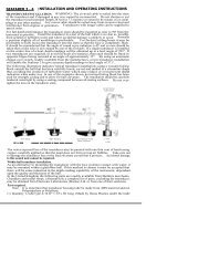
Sit<strong>in</strong>g<br />
For accurate speed read<strong>in</strong>gs the transducer should be sited with<strong>in</strong><br />
shaded clear flow <strong>areas</strong> .<br />
1 Sail 2 Plann<strong>in</strong>g power 3Displacement power<br />
The transducer should also:<br />
" be ahead of the propellers (10% W.L. length m<strong>in</strong>imum)<br />
" be at least 150mm (6<strong>in</strong>) awayfrom the keel (ideally ahead of the keel ifa<br />
sail<strong>in</strong>g yacht)<br />
" be as nearas possible the centrel<strong>in</strong>e of the vessel<br />
" be clear of other through-hull fitt<strong>in</strong>gs or projections<br />
" have sufficient clearance <strong>in</strong>side the hull to fit the nut<br />
" have 100mm K<strong>in</strong>) of headroom to allow for withdrawal<br />
Cabl<strong>in</strong>g<br />
1 . Run the cable back to the control head .<br />
Note: Avoid fluorescent lights, eng<strong>in</strong>es, radio transmitt<strong>in</strong>g equipment etc . as<br />
these maycause <strong>in</strong>terference . Also, keep the transducer cable clear of bilges<br />
and secure at regular <strong>in</strong>tervals .<br />
2 . Fit the transducerand <strong>in</strong>strument cable connectors together . To lock<br />
the connectors, push and rotate the r<strong>in</strong>gon the transducer cable<br />
connector towards the <strong>in</strong>strument connector .
Chapter 3 : Fault F<strong>in</strong>d<strong>in</strong>g and Ma<strong>in</strong>tenance<br />
3 .1 Fault F<strong>in</strong>d<strong>in</strong>g<br />
All <strong>Autohelm</strong> products are, priorto pack<strong>in</strong>gand shipp<strong>in</strong>g, subjectedto<br />
comprehensive test and quality assurance programmes . However, if a fault<br />
arises with the ST50 Plus Speed, thefollow<strong>in</strong>g table will help to identify the<br />
probable cause and provide the most likely cure .<br />
Fault Cause Action<br />
Instrument display<br />
blank .<br />
No supply . Check supply .<br />
Check cabl<strong>in</strong>g and<br />
security of SeaTalk<br />
connectors .<br />
Check fuse/breaker .<br />
Return unit for repair .<br />
Instrument displays<br />
'CODELOCK set',<br />
ENTER CODE<br />
The 'Code Lock' feature<br />
has been set .<br />
Enter correct code<br />
number .<br />
No speed or<br />
temperature<br />
<strong>in</strong>formation .<br />
Transducer cabl<strong>in</strong>g<br />
problem .<br />
Check cabl<strong>in</strong>g and<br />
security of transducer<br />
connector.<br />
No speed <strong>in</strong>formation .<br />
No exchange of<br />
<strong>in</strong>formation between<br />
SeaTalk <strong><strong>in</strong>struments</strong> .<br />
Failure of a group of<br />
<strong><strong>in</strong>struments</strong> <strong>in</strong> SeaTalk<br />
cha<strong>in</strong> .<br />
Transducer<br />
paddlewheel fouled .<br />
SeaTalk cabl<strong>in</strong>g<br />
problem .<br />
SeaTalk<br />
cabl<strong>in</strong>g/connector<br />
problem .<br />
Clean paddlewheel .<br />
Check security of<br />
SeaTalk connectors .<br />
Disconnect <strong><strong>in</strong>struments</strong><br />
one by one to isolate<br />
faulty unit .<br />
Check security of<br />
SeaTalk connectors<br />
and non-function<strong>in</strong>g<br />
units .
3.2 Ma<strong>in</strong>tenance<br />
Instrument<br />
Transducer<br />
Certa<strong>in</strong> atmospheric conditions may cause condensation to form on the<br />
control head w<strong>in</strong>dow . This will not harm the <strong>in</strong>strument and can be cleared by<br />
<strong>in</strong>creas<strong>in</strong>g the illum<strong>in</strong>ation sett<strong>in</strong>g to Level 3 .<br />
Chemical and abrasive materials must not be used to clean the ST50 Plus<br />
Speed <strong>in</strong>strument; if it is dirty, clean with a soft, damp cloth .<br />
Refer to the Installation and Ma<strong>in</strong>tenance <strong>in</strong>structions supplied with the<br />
transducer.<br />
Cabl<strong>in</strong>g<br />
Advice<br />
Exam<strong>in</strong>e all cables for chaf<strong>in</strong>g or damage to the outer shield and, where<br />
necessary, replace and resecure .<br />
For advice, or further <strong>in</strong>formation regard<strong>in</strong>g the <strong>in</strong>stallation of this product,<br />
please contact the <strong>Autohelm</strong> product Support Department oryour own<br />
National Distributor.
Chapter 4: Operation<br />
As it leaves the factory the ST50 Plus Speed is set to :<br />
" display speed <strong>in</strong> knots<br />
" display distance <strong>in</strong> Nm<br />
" master mode<br />
" 'CODE Lock' switched off<br />
These sett<strong>in</strong>gs can bechanged <strong>in</strong> calibration, Chapter 6.<br />
When the unit is powered up for the first time boat speed will be displayed.<br />
However,from this po<strong>in</strong>tonwards the last active screen will be displayed<br />
when the unit is powered up.
4.1 Speed Key
Speed Notes<br />
VMG (Velocity Made Good) is only available if a SeaTalkw<strong>in</strong>d <strong>in</strong>strument is<br />
<strong>in</strong>cluded <strong>in</strong> your system .<br />
Maximum speed can be reset by press<strong>in</strong>g RESET.<br />
Average speed maybe reset by press<strong>in</strong>gRESET.
4.2 Trip Key
Trip Notes<br />
Trip distance can be set to zero by press<strong>in</strong>g RESET for 3 seconds .<br />
Note:The display will flash until itchanges to zero .<br />
Distance lost (Tack) calculates the distance lost dur<strong>in</strong>g a tack as a result of<br />
the reduction <strong>in</strong> boatspeed . The distance lost is based on the average boat<br />
speed over30 seconds prior to selection of the distance lost display.<br />
If RESET is pressed while TACK' is selected, the display will change to show<br />
an alternat<strong>in</strong>g message'DISTANCE/LOST For DISTANCE/LOST MTR<br />
depend<strong>in</strong>g on the units selected <strong>in</strong> calibration .<br />
Distance lost will count up until the vessel reaches the average speed of the<br />
previous tack.<br />
Press RESET to set 'TACK' to zero <strong>in</strong> read<strong>in</strong>ess for the next tack.<br />
Note: The tack function should be reset at least 30 seconds before tack<strong>in</strong>g<br />
so that the average speed can be accurately calculated .
4.3 Timer Key<br />
(Vote:Thetimer can be reset by press<strong>in</strong>g the RESETkeywhile thetimer is<br />
runn<strong>in</strong>g .
.<br />
Timer Notes<br />
Dur<strong>in</strong>g the 5 or 10 m<strong>in</strong>ute countdown the follow<strong>in</strong>g audible alarms will sound :<br />
" double beep every m<strong>in</strong>ute<br />
" beep three times at 30 seconds to zero<br />
" beep everysecond from 10 seconds to zero<br />
" beep twice when the timer reaches zero and beg<strong>in</strong>s to count up.<br />
You can, once the 5or 10 m<strong>in</strong>ute countdown timer has been activated,<br />
return toone of the ma<strong>in</strong> speed displays. The timer will cont<strong>in</strong>ue to operate <strong>in</strong><br />
the background sound<strong>in</strong>g the alarms described above .<br />
These alarms canbe switched off if required (refer to para 6 .1, Initial<br />
Calibration for procedures) .
4.4 Display Contrast<br />
Thecontrast can be adjusted to achieve optimum legibility at any angle .<br />
1 . Momentarilypress SPEED and TRIP together .<br />
2 . Press TIMERor RESETto <strong>in</strong>crease or decrease the contrast sett<strong>in</strong>g<br />
(the range be<strong>in</strong>g between 1 and 15).<br />
Note: A high sett<strong>in</strong>g will suit <strong>in</strong>stallations where the control head willbe<br />
viewed from above.<br />
3 . PressSPEEDandTRIP together momentarily to store the contrast<br />
sett<strong>in</strong>g .
Chapter 5 : CODE Lock Security<br />
The ST50 Plus range <strong>in</strong>corporates an anti-theft feature called 'CODE<br />
Lock' . Designed to protect <strong>in</strong>dividual <strong><strong>in</strong>struments</strong> or complete systems <strong>in</strong><br />
<strong>vulnerable</strong> <strong>areas</strong>, 'CODE Lock' is a four digit number that you programme<br />
<strong>in</strong>to the permanent memory of a selected 'master' <strong>in</strong>strument .<br />
Note : A 'master' <strong>in</strong>strument is a digital unit on which the code number<br />
can be entered, and then, if part of an <strong>in</strong>tegrated system, transmitted to<br />
other ST50 Plus <strong>in</strong>truments .<br />
This facility means that, should a CODE Locked <strong>in</strong>strument be removed<br />
from the vessel without your permission, it cannot be operated without<br />
the four digit security number.<br />
'CODE Lock' can be used <strong>in</strong> one of three modes :<br />
Mode 1 : Off<br />
As it leaves the factory 'CODE Lock' is set to off. In this mode the<br />
<strong>in</strong>strument will operate normally when it is switched on, however, the unit<br />
will not be protected by the anti-theft feature .<br />
Mode 2 : 'CODE Lock' Once-Only Entry (page 23)<br />
This mode is designed for systems with a digital ST50 Plus <strong>in</strong>strument <strong>in</strong><br />
a safe, below-decks location . This <strong>in</strong>strument can then be used as a<br />
'master' to enter the four digit code number and, when the power is<br />
switched on, automatically transmit the code to all the <strong><strong>in</strong>struments</strong> <strong>in</strong> the<br />
system . The advantage of this mode is that, with the master safely below<br />
deck, code entry via the keypad is a once-only operation on <strong>in</strong>stallation .<br />
Once 'CODE Lock' is set the system will operate normally as soon as the<br />
power is switched on . In otherwords, the 'CODE Lock' security number is<br />
<strong>in</strong>visible .
Mode 3: 'CODE Lock' <strong>in</strong>put at Power-On (page 24)<br />
In the 'Power-0n mode', the ST50 Plus is configured so that you have to<br />
enter the four digit number on a 'master' digital <strong>in</strong>strument every time the<br />
system is switched on . Until this number is entered the<br />
<strong>in</strong>strument(s) will not operate .<br />
This mode is particularly useful when you are unable to position a 'master'<br />
<strong>in</strong>strument below decks and, therefore, all the vessels valuable <strong>in</strong>strumentation<br />
is left <strong>in</strong> a <strong>vulnerable</strong> area .<br />
Should a CODE Locked <strong>in</strong>strument be removed from the system, it will<br />
not operate until the correct four digit security number is entered or<br />
received .<br />
If your selected master <strong>in</strong>strument fails for any reason, the security code<br />
number can be entered via another ST50 Plus <strong>in</strong>strument <strong>in</strong> the system .<br />
However, until another <strong>in</strong>strument is set as a master or the exist<strong>in</strong>g<br />
master is replaced, the security code will have to be entered every time<br />
the system is switched on .<br />
Note: A warn<strong>in</strong>g sticker is provided with each <strong>in</strong>strument. If you have set<br />
'CODE Lock', position this warn<strong>in</strong>g sticker <strong>in</strong> a prom<strong>in</strong>ent location to deter<br />
potential thieves .<br />
Sett<strong>in</strong>g Up the Security Code<br />
When the ST50 Plus Speed is switched on for the first time the security<br />
feature is set to off . To turn the 'CODE Lock' feature on, proceed as<br />
follows :
Once Only Entry<br />
Action<br />
1 Press and SPEED and TRIP together for 4<br />
seconds<br />
Display Shows<br />
CAL after 2 seconds and<br />
VER X.X after 4 seconds<br />
2 Press SPEED twice CODELOCK Cal . Off<br />
3 4 seconds after 'CODELOCK Cal . Off' ENTER CODE<br />
4 Press TRIP<br />
5 Press TIMER or RESET to select first<br />
number<br />
6 Press TRIP to accept number 1'_'_ _<br />
7 Press TIMER or RESET to select second<br />
number<br />
8 Press TRIP to accept number 12'_'_<br />
9 Press TIMER or RESET to select third<br />
number<br />
1_ _<br />
12 _<br />
123_<br />
10 Press TRIP to accept third number 123'_'<br />
11 Press TIMER or RESET to select fourth<br />
number<br />
1234<br />
12 Press TRIP to accept code '1234'<br />
13 Press TRIP PWR ON?<br />
14 Leave PWR ON? flash<strong>in</strong>g for 10 seconds CODELOCK Cal . set<br />
15 To exit CODELOCK, press SPEED and TRIP<br />
together for 2 seconds<br />
Normal operation, eg .<br />
speed display<br />
If you do not exit 'CODELOCK Cal . set with<strong>in</strong> 10 seconds the display will<br />
change to CANCEL CODE . You now have the option of cancell<strong>in</strong>g the<br />
code, by press<strong>in</strong>g TRIP to return to the display, or exit as<br />
described <strong>in</strong> action 15 above .<br />
Your Code Number<br />
For future reference, enter your chosen code number <strong>in</strong>to the box below .<br />
For obvious reasons, please store this handbook <strong>in</strong> a safe place .<br />
Operation<br />
Once only 'CODE Lock' entry is <strong>in</strong>visible once it has been set .
On Power-Up<br />
Action<br />
1 Press and SPEED and TRIP together for 4<br />
seconds<br />
Display Shows<br />
CAL after 2 seconds and<br />
VER X.X after 4 seconds<br />
2 Press SPEED twice CODELOCK Cal . Off<br />
3 4 seconds after 'CODELOCK Cal . Off' ENTER CODE<br />
4 Press TRIP _<br />
'_'_ _<br />
5 Press TIMER or RESET to select first<br />
number<br />
1_ _<br />
6 Press TRIP to accept number<br />
7 Press TIMER or RESET to select second<br />
number<br />
12_ _<br />
8 Press TRIP to accept number 12'_'_<br />
9 Press TIMER or RESET to select third<br />
number<br />
123_<br />
10 Press TRIP to accept third number 123'_'<br />
11 Press TIMER or RESET to select fourth<br />
number<br />
1234<br />
12 Press TRIP to accept code '1234'<br />
13 Press TRIP PWR ON?<br />
14 Press TRIP with<strong>in</strong> 10 seconds CODELOCK Cal . set<br />
15 To exit CODELOCK, press SPEED and TRIP<br />
together for 2 seconds<br />
Normal operation, eg .<br />
speed display<br />
If you do not exit 'CODELOCK Cal . set' with<strong>in</strong> 10 seconds the display will<br />
change to CANCEL CODE . You now have the option of cancell<strong>in</strong>g the<br />
code, by press<strong>in</strong>g TRIP to return to the display, or exit as<br />
described <strong>in</strong> action 15 above .<br />
Your Code Number<br />
For future reference, enter your chosen code number <strong>in</strong>to the box below.<br />
For obvious reasons, please store this handbook <strong>in</strong> a safe place .<br />
Operation<br />
When the unit is powered on you are prompted to enter the code number .<br />
To enter the number, carry out actions 4 to 12 above and pressTRIP .
Chapter 6: Calibration<br />
As it leaves the factory the ST50 Plus Speed is set to display speed <strong>in</strong><br />
knots, distance <strong>in</strong> Nm and distance lost <strong>in</strong> feet . These sett<strong>in</strong>gs, together<br />
and other navigational features, can be changed (e .g ., Kts to Mph) as<br />
described <strong>in</strong> this section .
6.1 Initial Calibration<br />
Press SPEED and TRIP for 2 seconds to exit, store the <strong>in</strong>itial calibration<br />
sett<strong>in</strong>gs, and return to the speed display .
Initial Calibration Notes<br />
Press RESET to select the required speed, distance, and distance lost<br />
units .<br />
The countdown alarm can be turned on or off us<strong>in</strong>g the RESET key:<br />
1 = Alarm on (enabled)<br />
0 = Alarm off (disabled)<br />
Press SPEED momentarily to exit <strong>in</strong>itial calibration without stor<strong>in</strong>g the new<br />
sett<strong>in</strong>gs .<br />
Note: Initial calibration cannot be accessed when the unit is configured as<br />
a repeater .
6.2 Log Calibration<br />
The ST50 Plus Speed should not be used for navigational purposes until<br />
the transducer paddlewheel has been calibrated to the vessel . This is a<br />
simple operation that can be carried out automatically over a measured<br />
distance or by manually enter<strong>in</strong>g a calibration factor .<br />
Automatic Calibration<br />
Automatic calibration should be carried out when tidal flow is at a<br />
m<strong>in</strong>imum . Locate an easily identified, marked and measured distance on a<br />
chart and enter this distance <strong>in</strong>to the <strong>in</strong>strument (3) .<br />
Note: The measured distance should, ideally, be between<br />
1 and 2 .5 Nm/ Miles<br />
Proceed from object 1 to object 2 (measured distance), press<strong>in</strong>g the<br />
SPEED key at the start and f<strong>in</strong>ish of the run (4 and 5) . The calibration<br />
factor is calculated and displayed at the end of each run (6).<br />
Repeat the run overthe measured distance <strong>in</strong> the opposite direction . Once<br />
aga<strong>in</strong> the calibration factor will be displayed . This represents the average<br />
for the two runs . A further two runs can be made if required . Don't forget<br />
to store the log calibration factor .<br />
Note: The log calibration range is from 0 .25 to 2.00. Calibration factors<br />
outside of this range cannot be stored .
Note : Once you have completed the runs, store the calculated calibration<br />
factor by press<strong>in</strong>g SPEED and TRIP together until the displays returns to<br />
normal mode (approximately 2 seconds) .
Manual Log Calibration<br />
The follow<strong>in</strong>g calculation must be used when carry<strong>in</strong>g out Manual Log<br />
Calibration :<br />
F (Correction Factor) = Known Distance/Measured Distance<br />
The Known distance is the distance between two charted objects (e .g .,<br />
two buoys) .<br />
The Measured distance is the distance recorded by the speed <strong>in</strong>strument,<br />
allow<strong>in</strong>g for tidal flow.<br />
To obta<strong>in</strong> the correction factor (F) proceed from object 1 to object 2 and<br />
then object 2 to object l . The measured distance <strong>in</strong> each case must be<br />
noted, added together, and then divided by 2 to obta<strong>in</strong> the average<br />
distance .<br />
To obta<strong>in</strong> the correction factor, divide the known distance by the average<br />
distance . Once the correction factor has been calculated it can be entered<br />
<strong>in</strong>to the <strong>in</strong>strument as described <strong>in</strong> the flowchart on the follow<strong>in</strong>g page . Do<br />
not forget to store the correction factor .<br />
Note: The log calibration range is from 0 .25 to 2.00. Calibration factors<br />
outside of this range cannot be stored .
Note: The correction factor must be saved once it has been entered . This<br />
is achieved by press<strong>in</strong>g SPEED and TRIP together until the display returns<br />
to its normal mode (approximately 2 seconds) .
6 .3 Intermediate Calibration<br />
" To exit <strong>in</strong>termediate calibration and store the new sett<strong>in</strong>gs, press<br />
SPEED and TRIP for 2 seconds .<br />
Note : Initial calibration cannot be accessed when the unit is configured as<br />
a repeater .
Intermediate Calibration Notes<br />
(1) Master/Repeater Selection<br />
The ST50 Plus Speed is factory set as a master unit- normally connected<br />
to a speed transducer . It can, however, be set to repeat speed related<br />
<strong>in</strong>formation received via the SeaTalk bus :<br />
0 = master mode<br />
1 = repeater mode<br />
The follow<strong>in</strong>g functions are not available when set to repeater mode :<br />
" Log calibration<br />
" Trip distance reset<br />
" Average speed reset<br />
(2) Security Code<br />
Full details on how the 'CODE Lock' security feature works, is set-up, and<br />
stored are given <strong>in</strong> Chapter 5 .
6.4 Extended Calibration<br />
Extended calibration sett<strong>in</strong>gs are stored by press<strong>in</strong>g SPEED and TRIP for<br />
2 seconds .
Extended Calibration Notes<br />
All of the extended calibration screens are adjusted us<strong>in</strong>g the TIMER and/<br />
orRESET keys .<br />
Calibration allows you to protect your selected sett<strong>in</strong>gs aga<strong>in</strong>st accidental<br />
change . When lock is enabled the <strong>in</strong>itial and <strong>in</strong>termediate calibration<br />
sett<strong>in</strong>gs cannot be modified .<br />
CAL 1 = Calibration unlocked, i .e . normal access<br />
CAL 0 = Calibration locked, i .e . no access<br />
Once locked, calibration can be unlocked by enter<strong>in</strong>g extended calibration<br />
and select<strong>in</strong>g calibration unlocked .<br />
Speed and VMG damp<strong>in</strong>g adjusts the rate atwhich these displays are<br />
updated . The damp<strong>in</strong>g range is 1 to 15 seconds, with the factory default<br />
set at 4 seconds .<br />
Speed damp<strong>in</strong>g is displayed as 'DAMP A' and VMG damp<strong>in</strong>g as 'DAMP B' .<br />
Compatibility is set to BOTH and should not be changed .<br />
Caution : The 'Boat Show' mode is a dealer demonstration program only.<br />
Under no circumstances must this program be engaged when this unit is<br />
<strong>in</strong>stalled on-board your vessel . The display must, therefore, be left set to<br />
'BSHOW 0' .
Chapter 7: General Specification<br />
Dimensions :<br />
Power supply:<br />
Powerconsumption:<br />
Temperature range:<br />
Speed through water :<br />
Trip distance :<br />
Log :<br />
Average speed:<br />
Maximum speed :<br />
Sea Temperature:<br />
Units:<br />
Repeater capability :<br />
Illum<strong>in</strong>ation :<br />
Manual log calibration :<br />
Transducer speed range :<br />
110 x 110mm (4 .33 x 4 .33<strong>in</strong>)<br />
10 to 16V<br />
30ma (normal) 100ma (illum<strong>in</strong>ation on)<br />
0 to70 deg.C<br />
0 to 99 .9 Kts or Mph<br />
(0 .1 or 0.01 <strong>in</strong>crements)<br />
0 to999 Nm or Miles<br />
(0 .01 <strong>in</strong>crementsfrom0 to 9.99,<br />
0 .1 <strong>in</strong>crements to 99.9<br />
and 1 .0 <strong>in</strong>crements to 999)<br />
0 to99999 .9 Nm or Miles<br />
(0 .1 <strong>in</strong>crements)<br />
0 to99 .9 Kts orMph<br />
(0 .1 or 0 .01 <strong>in</strong>crements)<br />
0 to99 .9 Kts or Mph<br />
(0 .1 or 0 .01 <strong>in</strong>crements)<br />
-10 to +40 °C (14 to 104°F)<br />
(0 .1 <strong>in</strong>crements)<br />
Software programmable<br />
Softwareprogrammable<br />
3 levels plus off<br />
0 .25 to 2 .00 (correction factor)<br />
0 .8 to 40 Knots (1 to 46 Mph)
A Raytheon<br />
<strong>Autohelm</strong><br />
Company<br />
Nautech Limited, Anchorage Park, Portsmouth<br />
P03 5TD, England<br />
Telephone(0705) 693611 . Fax(0705) 694642