Directions for Use, Vital Signs Monitor 300 Series - afhcan
Directions for Use, Vital Signs Monitor 300 Series - afhcan
Directions for Use, Vital Signs Monitor 300 Series - afhcan

You also want an ePaper? Increase the reach of your titles
YUMPU automatically turns print PDFs into web optimized ePapers that Google loves.
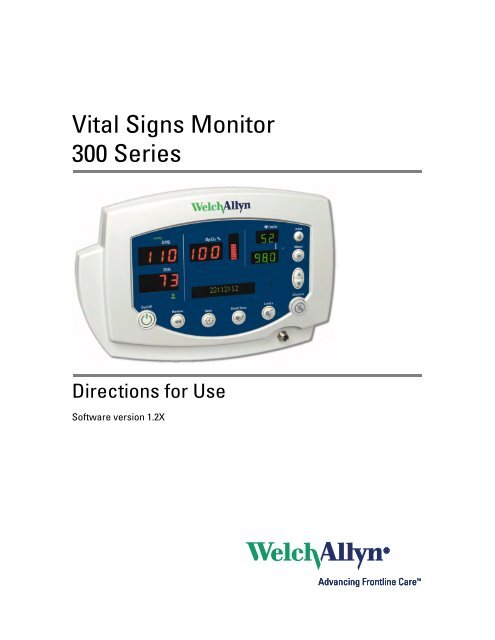
<strong>Vital</strong> <strong>Signs</strong> <strong>Monitor</strong><br />
<strong>300</strong> <strong>Series</strong><br />
<strong>Directions</strong> <strong>for</strong> <strong>Use</strong><br />
Software version 1.2X
ii<br />
Welch Allyn <strong>Vital</strong> <strong>Signs</strong> <strong>Monitor</strong> <strong>300</strong> <strong>Series</strong><br />
© 2009 Welch Allyn. All rights are reserved. No one is permitted to reproduce or duplicate, in any <strong>for</strong>m,<br />
this manual or any part thereof without permission from Welch Allyn.<br />
Welch Allyn assumes no responsibility <strong>for</strong> any injury to anyone, or <strong>for</strong> any illegal or improper use of the<br />
product, that may result from failure to use this product in accordance with the instructions, cautions,<br />
warnings, or statement of intended use published in this manual.<br />
Welch Allyn is a registered trademark of Welch Allyn.<br />
Nellcor is a registered trademark of Nellcor Puritan Bennett Inc.<br />
Software in this product is copyright Welch Allyn or its vendors. All rights are reserved. The software is<br />
protected by United States of America copyright laws and international treaty provisions applicable<br />
worldwide. Under such laws, the licensee is entitled to use the copy of the software incorporated with<br />
this instrument as intended in the operation of the product in which it is embedded. The software may not<br />
be copied, decompiled, reverse-engineered, disassembled or otherwise reduced to human-perceivable<br />
<strong>for</strong>m. This is not a sale of the software or any copy of the software; all right, title and ownership of the<br />
software remains with Welch Allyn or its vendors.<br />
For in<strong>for</strong>mation about any Welch Allyn product, call Welch Allyn Technical Support:<br />
USA + 1 315 685 4560<br />
800 535 6663<br />
Australia + 61 29 638 <strong>300</strong>0<br />
800 074 793<br />
Canada 800 561 8797 China + 86 216 327 9631<br />
European Call + 353 46 906 7790 France + 33 1 6009 3366<br />
Center<br />
Germany + 49 747 792 7186 Japan + 81 33 219 0071<br />
Latin America + 1 305 669 9003 Netherlands + 31 15 750 5000<br />
Singapore + 65 6419 8100 South Africa + 27 11 777 7555<br />
United Kingdom + 44 207 365 6780 Sweden + 46 85 853 6551<br />
REF: 810-2252-XX<br />
REF 810-2221-XX (Printed, English only)<br />
Manual Part Number 810-2223-03 Ver A, 2009-09<br />
Welch Allyn, Inc.<br />
8500 SW Creekside Place<br />
Beaverton, OR 97008-7107 USA<br />
Welch Allyn Ltd<br />
Navan Business Park<br />
Dublin Road, Navan<br />
County Meath, Republic of Ireland<br />
www.welchallyn.com
iii<br />
Contents<br />
1 - General In<strong>for</strong>mation . . . . . . . . . . . . . . . . . . . . . . . . . . . . . . . . . . . . . . 1<br />
About This Manual . . . . . . . . . . . . . . . . . . . . . . . . . . . . . . . . . . . . . . . . . . . . . . . . 1<br />
Intended <strong>Use</strong> . . . . . . . . . . . . . . . . . . . . . . . . . . . . . . . . . . . . . . . . . . . . . . . . . . . . 1<br />
Symbols . . . . . . . . . . . . . . . . . . . . . . . . . . . . . . . . . . . . . . . . . . . . . . . . . . . . . . . . 2<br />
Product Overview . . . . . . . . . . . . . . . . . . . . . . . . . . . . . . . . . . . . . . . . . . . . . . . . . 3<br />
Warnings and Cautions. . . . . . . . . . . . . . . . . . . . . . . . . . . . . . . . . . . . . . . . . . . . . 4<br />
Displays, Indicators, Controls, and Connections. . . . . . . . . . . . . . . . . . . . . . . . . . 6<br />
2 - Setup . . . . . . . . . . . . . . . . . . . . . . . . . . . . . . . . . . . . . . . . . . . . . . . . . . 9<br />
Connections . . . . . . . . . . . . . . . . . . . . . . . . . . . . . . . . . . . . . . . . . . . . . . . . . . . . . 9<br />
Power On, Power-on Self-Test, and Power Off . . . . . . . . . . . . . . . . . . . . . . . . . . 15<br />
Configuring Operating Parameters . . . . . . . . . . . . . . . . . . . . . . . . . . . . . . . . . . . 16<br />
3 - Patient <strong>Monitor</strong>ing . . . . . . . . . . . . . . . . . . . . . . . . . . . . . . . . . . . . . . 29<br />
<strong>Monitor</strong>ing Blood Pressure . . . . . . . . . . . . . . . . . . . . . . . . . . . . . . . . . . . . . . . . . 29<br />
<strong>Monitor</strong>ing Pulse Rate . . . . . . . . . . . . . . . . . . . . . . . . . . . . . . . . . . . . . . . . . . . . 36<br />
<strong>Monitor</strong>ing SpO 2 . . . . . . . . . . . . . . . . . . . . . . . . . . . . . . . . . . . . . . . . . . . . . . . . . 37<br />
<strong>Monitor</strong>ing Temperature . . . . . . . . . . . . . . . . . . . . . . . . . . . . . . . . . . . . . . . . . . . 40<br />
4 - Alarms and Alerts . . . . . . . . . . . . . . . . . . . . . . . . . . . . . . . . . . . . . . . 51<br />
Responding to a Patient Alarm . . . . . . . . . . . . . . . . . . . . . . . . . . . . . . . . . . . . . . 51<br />
Responding to an Equipment Alert. . . . . . . . . . . . . . . . . . . . . . . . . . . . . . . . . . . 52<br />
Alarm Indicators . . . . . . . . . . . . . . . . . . . . . . . . . . . . . . . . . . . . . . . . . . . . . . . . . 54<br />
Setting Alarms . . . . . . . . . . . . . . . . . . . . . . . . . . . . . . . . . . . . . . . . . . . . . . . . . . 54<br />
Nurse Call . . . . . . . . . . . . . . . . . . . . . . . . . . . . . . . . . . . . . . . . . . . . . . . . . . . . . . 57<br />
Error Codes. . . . . . . . . . . . . . . . . . . . . . . . . . . . . . . . . . . . . . . . . . . . . . . . . . . . . 58<br />
5 - Reviewing Patient Data. . . . . . . . . . . . . . . . . . . . . . . . . . . . . . . . . . . 59<br />
Displaying Stored Patient Data . . . . . . . . . . . . . . . . . . . . . . . . . . . . . . . . . . . . . . 59<br />
Printing Patient Data . . . . . . . . . . . . . . . . . . . . . . . . . . . . . . . . . . . . . . . . . . . . . . 59<br />
Erasing Patient Data . . . . . . . . . . . . . . . . . . . . . . . . . . . . . . . . . . . . . . . . . . . . . . 65<br />
Replacing the Printer Paper Supply. . . . . . . . . . . . . . . . . . . . . . . . . . . . . . . . . . . 66<br />
6 - Operator Maintenance . . . . . . . . . . . . . . . . . . . . . . . . . . . . . . . . . . . 67<br />
Cleaning . . . . . . . . . . . . . . . . . . . . . . . . . . . . . . . . . . . . . . . . . . . . . . . . . . . . . . . 67<br />
Storage . . . . . . . . . . . . . . . . . . . . . . . . . . . . . . . . . . . . . . . . . . . . . . . . . . . . . . . . 67<br />
Recycling <strong>Monitor</strong> Components . . . . . . . . . . . . . . . . . . . . . . . . . . . . . . . . . . . . . 68
iv Contents Welch Allyn <strong>Vital</strong> <strong>Signs</strong> <strong>Monitor</strong> <strong>300</strong> <strong>Series</strong><br />
7 - Reference . . . . . . . . . . . . . . . . . . . . . . . . . . . . . . . . . . . . . . . . . . . . . . 69<br />
Battery Operation . . . . . . . . . . . . . . . . . . . . . . . . . . . . . . . . . . . . . . . . . . . . . . . . 69<br />
<strong>Monitor</strong> Specifications . . . . . . . . . . . . . . . . . . . . . . . . . . . . . . . . . . . . . . . . . . . . 71<br />
Factory Default Settings . . . . . . . . . . . . . . . . . . . . . . . . . . . . . . . . . . . . . . . . . . . 80<br />
Limited Warranty . . . . . . . . . . . . . . . . . . . . . . . . . . . . . . . . . . . . . . . . . . 81<br />
Index . . . . . . . . . . . . . . . . . . . . . . . . . . . . . . . . . . . . . . . . . . . . . . . . . . . . 83
1<br />
1<br />
General In<strong>for</strong>mation<br />
About This Manual<br />
This manual contains in<strong>for</strong>mation about the Welch Allyn ® <strong>Vital</strong> <strong>Signs</strong> <strong>Monitor</strong> <strong>300</strong> <strong>Series</strong><br />
monitor. The series includes the following models:<br />
Model Features Model Features<br />
5<strong>300</strong>0 Standard (NIBP, Pulse Rate, and MAP) 53N00 Standard + Nellcor ® SpO 2<br />
5<strong>300</strong>P Standard + Printer 53NT0 Standard + Nellcor SpO 2 + Temperature<br />
530T0 Standard + Temperature 53N0P Standard + Nellcor SpO 2 + Printer<br />
530TP Standard + Temperature + Printer 53NTP Standard + Nellcor SpO 2 + Temperature + Printer<br />
Intended <strong>Use</strong><br />
All operators must read and understand this manual be<strong>for</strong>e using the monitor.<br />
All technicians and other service personnel must read and understand this manual be<strong>for</strong>e<br />
attempting to set up, configure, troubleshoot, or service the monitor.<br />
All in<strong>for</strong>mation in this manual, including the illustrations, is based on a monitor configured<br />
with the Temperature, SpO 2 , and Printer options. If your monitor configuration lacks any<br />
of these options, then some in<strong>for</strong>mation in this manual does not apply.<br />
The VSM series of monitors are intended to be used by clinicians and medically qualified<br />
personnel <strong>for</strong> monitoring of noninvasive blood pressure, pulse rate, body temperature,<br />
noninvasive functional oxygen saturation of arteriolar hemoglobin (SpO2), and body<br />
temperature in normal and axillary modes of neonatal, pediatric and adult patients.<br />
The most likely locations <strong>for</strong> patients to be monitored are general med/surg. floors,<br />
general hospital and alternate care environments. This device is available <strong>for</strong> sale only<br />
upon the order of a physician or licensed health care professional.
2 Chapter 1 General In<strong>for</strong>mation Welch Allyn <strong>Vital</strong> <strong>Signs</strong> <strong>Monitor</strong> <strong>300</strong> <strong>Series</strong><br />
Symbols<br />
The symbols illustrated on the following pages appear on the monitor or in this document.<br />
Table 1. Symbols: Certification and Operation<br />
This device has been tested and certified by<br />
the Canadian Standards Association<br />
International to comply with applicable U.S.<br />
and Canadian medical safety standards.<br />
The CE Mark and Notified Body Registration<br />
Number signify that the device meets all<br />
essential requirements of the European<br />
Medical Device Directive 93/42/EEC.<br />
Australian Registered Importer<br />
Urgent alarm notification (output to Nurse Call<br />
system)<br />
Recycle used batteries properly and in<br />
accordance with local regulations.<br />
Do not dispose of batteries in refuse containers.<br />
Sealed lead-acid battery, 6V 4 Ah<br />
Recycle the monitor and battery separately from other disposables. (See “Recycling <strong>Monitor</strong> Components”<br />
on page 68.)<br />
Patient connections are Type BF, and protected against defibrillation.<br />
WARNING Indicates conditions that could lead to illness, injury, or death.<br />
Caution In this manual, indicates conditions that could damage equipment or other property.<br />
Caution On the product, means “Consult accompanying documentation.”<br />
Table 2. Symbols: Shipping, Storing, and Environment<br />
Keep this end of the package or shipping<br />
crate up.<br />
Fragile contents—handle with care.<br />
Do not expose the monitor to relative<br />
humidity above this limit.<br />
Protect the monitor from exposure to rain.<br />
Do not subject the monitor to altitudes outside<br />
these limits.<br />
Limit stacking to this number of units.<br />
Do not expose the monitor to temperatures<br />
outside these limits.<br />
Table 3. Symbols: Connectors<br />
Temperature Probe Cable Connector SpO2 SpO 2 Sensor Cable Connector<br />
RS232 Cable Connector<br />
Nurse Call Cable Connector<br />
AC Power Adapter Cable Connector<br />
NIBP Hose Connector<br />
Table 4. Symbols: Printer Door<br />
Press to open the printer door<br />
Load paper this direction
<strong>Directions</strong> <strong>for</strong> <strong>Use</strong> Chapter 1 General In<strong>for</strong>mation 3<br />
The functions of the monitor front panel controls illustrated here are described in detail<br />
elsewhere in this document.<br />
Table 5. Front Panel Controls<br />
Set alarm limits<br />
Power on/off<br />
Silence alarms<br />
Scroll up/down<br />
Scroll <strong>for</strong>ward/back<br />
Increase/decrease value<br />
(The scroll icon appears as these two arrows<br />
in the documentation.)<br />
Set an NIBP automatic measurement interval<br />
Print patient data<br />
Review patient data<br />
Start/stop an NIBP cycle (AUTO button)<br />
Cycle to the next menu selections<br />
Table 6. Front Panel Displays and Indicators<br />
SYS<br />
DIA<br />
SpO2<br />
message<br />
window<br />
ºC<br />
ºF<br />
M<br />
Systolic pressure<br />
Diastolic pressure<br />
Arterial hemoglobin oxygen saturation<br />
Pulse rate<br />
MAP (mean arterial pressure)<br />
Degrees Celsius<br />
Degrees Fahrenheit<br />
<strong>Monitor</strong>ed temperature<br />
Battery discharged<br />
pulse<br />
amplitude<br />
indicator<br />
Temperature<br />
Pulse strength<br />
Neonatal<br />
Pediatric<br />
Adult<br />
AC power<br />
Battery charging (flashing)<br />
Battery charged (steady)<br />
Product Overview<br />
The monitor can monitor systolic and diastolic noninvasive blood pressure (NIBP), pulse<br />
rate, and MAP (mean arterial pressure). Units configured with the appropriate options can<br />
also simultaneously monitor temperature and SpO 2 , and can continuously monitor<br />
pulse rate.<br />
All vital-sign measurements are displayed on the front panel of the monitor. These<br />
measurements can also be printed, using the optional integrated thermal printer.<br />
The monitor provides programmable audible and visual alarms and automatic NIBP<br />
measurements at selectable intervals. It can also be configured to provide an alarmactivated<br />
Nurse Call function.<br />
Accessory equipment connected to the analog and digital interfaces must be certified to<br />
the respective IEC standards (IEC 60950 <strong>for</strong> data-processing equipment, IEC 60601-1 <strong>for</strong>
4 Chapter 1 General In<strong>for</strong>mation Welch Allyn <strong>Vital</strong> <strong>Signs</strong> <strong>Monitor</strong> <strong>300</strong> <strong>Series</strong><br />
medical equipment). All such configurations must comply with system standard<br />
IEC 60601-1-1.<br />
Warnings and Cautions<br />
General Warnings<br />
Caution Anyone connecting additional equipment to the signal input part or<br />
signal output part of this monitor configures a medical system and is<br />
responsible <strong>for</strong> verifying that the system complies with the requirements of the<br />
system standard IEC 60601-1-1. Changes or modifications not expressly approved<br />
by Welch Allyn could void the purchaser’s authority to operate the equipment.<br />
All operating and service personnel must be familiar with the in<strong>for</strong>mation presented here,<br />
and with other warnings and cautions which appear throughout this document.<br />
Warning and caution labels can appear on the monitor, the packaging, the shipping<br />
container, or in this document.<br />
WARNING Many environmental variables, including patient physiology and<br />
clinical application, can affect the accuracy and per<strong>for</strong>mance of the device. The<br />
clinician must verify all vital signs in<strong>for</strong>mation prior to patient intervention.<br />
WARNING The monitor is <strong>for</strong> use only by medical clinicians. Although this<br />
document might illustrate medical monitoring techniques, the monitor must be<br />
used only by trained clinicians who know how to take and interpret a patient’s<br />
vital signs.<br />
WARNING During defibrillation, keep the defibrillation discharge paddles away<br />
from any conductive parts that might already be in contact with the patient.<br />
WARNING For the safety of patients, and to ensure the best product<br />
per<strong>for</strong>mance and accuracy, use only accessories and supplies recommended or<br />
supplied by Welch Allyn <strong>for</strong> the monitor, as listed in Products and Accessories<br />
(810-0409-XX). Always use accessories with strict adherence to the<br />
manufacturer’s directions <strong>for</strong> use.<br />
WARNING Do not operate the monitor in the presence of magnetic resonance<br />
imaging (MRI) or hyperbaric chambers.<br />
WARNING Do not operate the monitor in the presence of a flammable<br />
anesthetic mixture with air, oxygen, or nitrous oxide, or in oxygen-enriched<br />
environments, or in any other potentially explosive environment.<br />
WARNING It is the clinician’s responsibility to set or verify alarm limits<br />
appropriate to each patient.<br />
WARNING Never allow any liquid to enter any monitor connector. If a connector<br />
does come in contact with liquid:<br />
1. Remove the monitor from service.<br />
2. <strong>Use</strong> warm, dry air to dry the connector.<br />
3. Thoroughly test and verify operation be<strong>for</strong>e returning the monitor to service.
<strong>Directions</strong> <strong>for</strong> <strong>Use</strong> Chapter 1 General In<strong>for</strong>mation 5<br />
General Cautions<br />
WARNING Do not connect more than one patient to a monitor.<br />
WARNING If the monitor is dropped or damaged, it must be thoroughly tested<br />
by a qualified service person be<strong>for</strong>e it is returned to service.<br />
WARNING Periodically check all cords and cables <strong>for</strong> damage, wear, or fraying;<br />
replace as needed.<br />
WARNING The monitor contains no operator-serviceable parts, other than the<br />
replaceable paper roll.<br />
WARNING If the battery shows any signs of damage, leakage, or cracking, it<br />
must be replaced immediately, by a qualified service person, and only with a<br />
battery approved by Welch Allyn.<br />
WARNING Always recycle batteries according to local regulations. Never<br />
dispose of batteries in refuse containers.<br />
WARNING Do not use the monitor on patients who are linked to a heart<br />
machine or a lung machine.<br />
WARNING Do not use the monitor on patients who are experiencing<br />
convulsions or tremors.<br />
WARNING Do not use the pulse oximeter as a replacement or substitute <strong>for</strong><br />
ECG-based arrhythmia analysis.<br />
Caution If the accuracy of any measurement is in doubt, verify the patient’s vital<br />
sign by another method. If the monitor is not measuring accurately, have it<br />
inspected by a qualified service person.<br />
Caution Be sure that the monitor is securely located on a flat surface or properly<br />
suspended by means of appropriate mounting equipment.<br />
Caution Do not autoclave the monitor.<br />
Caution Do not place cups, glasses, or other fluid containers or vessels on the<br />
monitor.<br />
Caution <strong>Use</strong>rs should check <strong>for</strong> audible alarm function every time the VSM <strong>300</strong><br />
is used. During the normal power-up cycle, two audible tones are emitted<br />
immediately after the self-test is complete. If these tones do not sound, the audio<br />
has failed. Remove the device from service and contact Welch Allyn.<br />
The loss of the audible alarm could cause a delay in a clinician learning of an alarm<br />
condition <strong>for</strong> the following conditions: 1) hypotension or hypertension, 2) low<br />
blood oxygen content (SpO 2 ), 3) low or high pulse rate, 4) other alarm conditions<br />
relating to the loss of monitoring of a patient (e.g., a “sensor off” condition). Such<br />
delay could potentially result in injury to the patient.
6 Chapter 1 General In<strong>for</strong>mation Welch Allyn <strong>Vital</strong> <strong>Signs</strong> <strong>Monitor</strong> <strong>300</strong> <strong>Series</strong><br />
Displays, Indicators, Controls, and Connections<br />
This section describes the measurement displays, status indicators, function controls, and<br />
connections of the monitor.<br />
Numeric Measurement and Message Displays<br />
SYS, DIA, and SpO2.<br />
Displays systolic and diastolic<br />
blood pressure and SpO 2 , or<br />
related alarm thresholds and<br />
error codes. (See “Error Codes”<br />
on page 58.)<br />
Displays pulse rate and<br />
temperature, or related alarm<br />
thresholds and error codes.<br />
(Message window)<br />
Displays the current date and time, MAP measurements, and alarm<br />
thresholds. Displays configuration settings, error codes, software version<br />
numbers, and printer status.
<strong>Directions</strong> <strong>for</strong> <strong>Use</strong> Chapter 1 General In<strong>for</strong>mation 7<br />
Status Indicators<br />
NIBP Measurement Units<br />
kilopascals<br />
millimeters of<br />
mercury<br />
kPa<br />
mmHg<br />
Temperature Units<br />
Pulse<br />
Amplitude Indicator ºF degrees Fahrenheit<br />
ºC<br />
degrees Celsius<br />
Patient type<br />
neonate<br />
pediatric<br />
Temperature Type<br />
M<br />
monitored<br />
alarms not silenced<br />
adult<br />
alarms silenced<br />
power<br />
is off<br />
power<br />
is on<br />
Battery Status<br />
charged ———<br />
charging - - - - -<br />
discharged
8 Chapter 1 General In<strong>for</strong>mation Welch Allyn <strong>Vital</strong> <strong>Signs</strong> <strong>Monitor</strong> <strong>300</strong> <strong>Series</strong><br />
Function Controls<br />
Print<br />
Menu<br />
Up/Down<br />
Power On/Off<br />
Power<br />
is on<br />
Power<br />
is off<br />
Review<br />
Data<br />
Set NIBP<br />
Interval<br />
Start/Stop NIBP<br />
(AUTO button)<br />
Set Alarm<br />
Limits<br />
Silence<br />
Alarms<br />
Alarms<br />
Silenced<br />
Connections<br />
Nurse Call Cable<br />
Connector<br />
30V , 1A Max.<br />
Temperature Probe<br />
Cable Connector<br />
SpO 2<br />
SpO 2 Sensor Cable<br />
Connector<br />
RS232 Cable<br />
Connector<br />
DC Power Cable<br />
Connector<br />
For in<strong>for</strong>mation on the connections, refer to the following:<br />
AC Power Adapter “Connecting AC Power” on page 9<br />
Temperature Probe “Connecting the Temperature Probe Cable” on page 12<br />
SpO 2 Sensor “Connecting and Disconnecting the SpO 2 Sensor Cable” on page 13<br />
NIBP Cuff Hose “Connecting the NIBP Cuff Hose” on page 11<br />
Nurse Call Cable “Nurse Call” on page 79
9<br />
2<br />
Setup<br />
Connections<br />
Connecting AC Power<br />
This chapter describes the set-up procedures <strong>for</strong> patient monitoring.<br />
<strong>Use</strong> the procedures described below to connect components to the monitor.<br />
The monitor operates on DC power, supplied by either the internal battery or the AC<br />
power adapter. (For in<strong>for</strong>mation on the battery, refer to “Battery Operation” on page 69<br />
and “Electrical” on page 74.)<br />
When the AC power adapter is connected, it simultaneously powers the monitor and<br />
charges the internal battery. When the AC power adapter is not connected, the monitor<br />
operates on the internal battery.<br />
Caution <strong>Use</strong> only the medical-grade AC power adapter approved by Welch Allyn.<br />
(Refer to the Welch Allyn Parts and Accessories Guide (810-0409-XX) <strong>for</strong> ordering<br />
in<strong>for</strong>mation.) Using an unqualified power adapter can have the following results:<br />
• violation of isolation requirements<br />
• hazard to the patient<br />
• damage to the monitor<br />
• nullification of the product warranty
10 Chapter 2 Setup Welch Allyn <strong>Vital</strong> <strong>Signs</strong> <strong>Monitor</strong> <strong>300</strong> <strong>Series</strong><br />
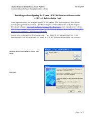
To use the AC power adapter:<br />
1. Plug the power adapter into the AC power source.<br />
2. Plug the power adapter connector into the monitor DC port.<br />
AC Power<br />
Adapter Port<br />
<strong>Use</strong> the AC power adapter to fully charge the battery be<strong>for</strong>e using the monitor. (This can<br />
take up to 12 hours.)<br />
Caution Fully charge the battery be<strong>for</strong>e using the monitor <strong>for</strong> the first time.<br />
Failure to do so will result in poor battery per<strong>for</strong>mance and reduced battery life.<br />
• While the monitor is charging, the AC/charging indicator flashes.<br />
• When the monitor is 90% charged, the AC/charging indicator is steady. To fully<br />
charge the battery, leave the AC power adapter connected <strong>for</strong> a few more hours.<br />
• After the monitor is fully charged <strong>for</strong> the first time, the monitor can be powered by the<br />
AC power adapter or by the internal battery.
<strong>Directions</strong> <strong>for</strong> <strong>Use</strong> Chapter 2 Setup 11<br />
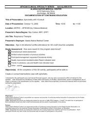
Connecting the NIBP Cuff Hose<br />
Attach the hose to the monitor and the cuff as follows, referring to the illustration below:<br />
1. Screw the hose connector onto the NIBP connector on the monitor.<br />
2. Connect the monitor hose connector to the mating connector on the cuff.<br />
For in<strong>for</strong>mation on NIBP measurements, see “Patient <strong>Monitor</strong>ing” on page 29.<br />
Threaded NIBP<br />
Hose Connector
12 Chapter 2 Setup Welch Allyn <strong>Vital</strong> <strong>Signs</strong> <strong>Monitor</strong> <strong>300</strong> <strong>Series</strong><br />
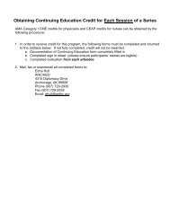
Connecting the Temperature Probe Cable<br />
Follow these steps to connect the temperature probe cable to the monitor.<br />
1. Locate the temperature probe connector port on the back of the monitor.<br />
2. Holding the temperature probe cable connector with the spring tab on the right,<br />
carefully insert it into the monitor temperature probe connector port. The spring tab<br />
clicks out when the connector halves are fully and correctly mated.<br />
3. To disconnect the temperature probe cable, depress the spring tab and withdraw the<br />
cable connector.<br />
Temperature Probe Cable<br />
Connector<br />
Temperature Probe<br />
Connector Port<br />
For in<strong>for</strong>mation on temperature measurements, see “Patient <strong>Monitor</strong>ing” on page 29.
<strong>Directions</strong> <strong>for</strong> <strong>Use</strong> Chapter 2 Setup 13<br />
Connecting and Disconnecting the SpO 2 Sensor Cable<br />
To connect the SpO2 sensor cable:<br />
1. Locate the SpO 2 sensor cable connector (labeled SpO2) on the side of the monitor.<br />
2. Note the hole patterns of the connector halves, and align the cable connector<br />
accordingly.<br />
Note<br />
Verify that the sensor cable connector has slots on both sides. If the cable<br />
connector has a slot on only one side, then the sensor is not compatible with the<br />
monitor.<br />
The SpO 2 connectors are notched and flanged to ensure proper fit. If the<br />
connectors do not join easily, stop and verify the following:<br />
• You have the correct SpO 2 sensor.<br />
• The cable connector is aligned correctly.<br />
3. Carefully insert the SpO 2 cable connector into the SpO 2 monitor connector.<br />
If you are using a sensor extension cable, plug the sensor into the extension cable and<br />
plug the extension cable into the monitor.
14 Chapter 2 Setup Welch Allyn <strong>Vital</strong> <strong>Signs</strong> <strong>Monitor</strong> <strong>300</strong> <strong>Series</strong><br />
To disconnect the SpO 2 cable, refer to the instructions shown in the illustration below.<br />
Note<br />
Always grasp the cable by the connector shoulder. Do not pull on the cable itself.<br />
Thumb presses the upper tab<br />
to free the connector.<br />
Thumb and <strong>for</strong>efinger grasp the<br />
shoulder of the connector cable<br />
to pull the cable connector out<br />
of the connector port.<br />
For in<strong>for</strong>mation on SpO 2 measurements, see “Patient <strong>Monitor</strong>ing” on page 29.
<strong>Directions</strong> <strong>for</strong> <strong>Use</strong> Chapter 2 Setup 15<br />
Power On, Power-on Self-Test, and Power Off<br />
When the battery is charged, press to turn on the monitor.<br />
The monitor runs a diagnostic self-test each time it powers up.<br />
• If all tested functions are working normally, the various windows briefly display<br />
start-up values (‘8’ and ‘- -’) and a short tone sounds twice.<br />
Caution <strong>Use</strong>rs should check <strong>for</strong> audible alarm function every time the VSM <strong>300</strong><br />
is used. During the normal power-up cycle, two audible tones are emitted<br />
immediately after the self-test is complete. If these tones do not sound, the audio<br />
has failed. Remove the device from service and contact Welch Allyn.<br />
The loss of the audible alarm could cause a delay in a clinician learning of an alarm<br />
condition <strong>for</strong> the following conditions: 1) hypotension or hypertension, 2) low<br />
blood oxygen content (SpO 2 ), 3) low or high pulse rate, 4) other alarm conditions<br />
relating to the loss of monitoring of a patient (e.g., a “sensor off” condition). Such<br />
delay could potentially result in injury to the patient.<br />
mmHg kPa<br />
SYS<br />
SpO2 %<br />
/min<br />
SYS<br />
SpO2 %<br />
/min<br />
8.8.8.<br />
18.8.<br />
DIA<br />
DIA<br />
8.8.8.<br />
****************<br />
****************<br />
1 2<br />
SYS<br />
DIA<br />
SpO2 %<br />
****************<br />
/min<br />
8.8.8.<br />
1.8.8.8.<br />
ºF<br />
ºC<br />
M<br />
3 4<br />
mmHg<br />
SYS<br />
0<br />
DIA<br />
0<br />
SpO2 %<br />
00:00:45<br />
/min<br />
0<br />
ºF<br />
• If the self-test fails, an error code appears in the SYS window.<br />
When the self-test is complete, the software version appears briefly in the message<br />
window, followed by the current time of day.<br />
Caution Always observe the monitor during power-up. If any display fails to<br />
illuminate properly, or if an error code appears in the systolic window, in<strong>for</strong>m your<br />
biomedical engineering department immediately, or call your nearest Welch Allyn<br />
Customer Service or Technical Support facility. Do not use the monitor until the<br />
problem is corrected.<br />
To shut off the monitor, press .<br />
Note<br />
Shutting off the monitor erases all stored patient data but does not erase settings<br />
or configuration parameters.
16 Chapter 2 Setup Welch Allyn <strong>Vital</strong> <strong>Signs</strong> <strong>Monitor</strong> <strong>300</strong> <strong>Series</strong><br />
Configuring Operating Parameters<br />
You can change several monitor operating parameters. When changed, these settings<br />
become the default power-up settings.<br />
How to <strong>Use</strong> the Menu System<br />
Settings Menu<br />
The monitor menu system contains three sets of menus—settings, configuration,<br />
and service.<br />
Access the settings menu by pressing the menu button<br />
Then press repeatedly to reach the setting of interest.<br />
while in normal operation.<br />
Settings Menu<br />
128<br />
71<br />
98<br />
MAP 90mmHg<br />
54<br />
37.0<br />
Patient Type<br />
Target Cuff Inflation Pressure<br />
Power Off - all values saved<br />
except target inflation pressure<br />
No action <strong>for</strong> 10 seconds<br />
or<br />
Press any button other than<br />
Temperature Units<br />
Temperature Type<br />
ºF ºC M<br />
Pulse Tone Volume
<strong>Directions</strong> <strong>for</strong> <strong>Use</strong> Chapter 2 Setup 17<br />
<strong>Use</strong> the settings menu to select and set the following parameters:<br />
Patient Type Neonate Term birth through 28 days, or up to 44 gestational weeks<br />
Pediatric<br />
Adult<br />
29 days through 12 years<br />
13 years and older<br />
Target Pressure<br />
Temp Modes<br />
Pulse Tone Volume<br />
The initial cuff inflation pressure (set individually <strong>for</strong> each patient type)<br />
ºF Fahrenheit Predictive<br />
ºF M Fahrenheit <strong>Monitor</strong>ed<br />
ºC Celsius Predictive<br />
ºC M Celsius <strong>Monitor</strong>ed<br />
From 0 (silent) to 5 (loudest)<br />
To change a settings parameter:<br />
1. Select the parameter as indicated above.<br />
2. Change the value by pressing or .<br />
3. Set the displayed new value either by doing nothing <strong>for</strong> 10 seconds or by pressing any<br />
button other than or . If you press a function button (such as ), the monitor<br />
returns to normal operation with that function ( ) activated.
18 Chapter 2 Setup Welch Allyn <strong>Vital</strong> <strong>Signs</strong> <strong>Monitor</strong> <strong>300</strong> <strong>Series</strong><br />
Configuration Menu<br />
The configuration menu is accessed by pressing and keeping it depressed <strong>for</strong> three<br />
seconds. You then press repeatedly until you reach the setting of interest.<br />
Configuration Menu<br />
128<br />
71<br />
98<br />
MAP 90 kPa<br />
54<br />
37.0<br />
Press and hold<br />
<strong>for</strong> 3 seconds<br />
Set Time and Date<br />
MAP<br />
Enable<br />
Disable<br />
Power Off - all values saved<br />
NIBP Units<br />
mmHg<br />
kPa<br />
Press and hold <strong>for</strong> 3<br />
seconds<br />
No action <strong>for</strong> 10 seconds<br />
Print<br />
Stream<br />
Batch<br />
Press any button other than
<strong>Directions</strong> <strong>for</strong> <strong>Use</strong> Chapter 2 Setup 19<br />
<strong>Use</strong> the configuration menu to select and set the following parameters:<br />
Time and Date<br />
MAP Measurement<br />
Blood Pressure<br />
Measurement Units<br />
Print Mode<br />
hour<br />
minute<br />
year<br />
month<br />
day<br />
Enabled<br />
Disabled<br />
mmHg (millimeters of mercury)<br />
kPa (kilopascals)<br />
Batch<br />
Stream<br />
To change a configuration parameter:<br />
1. Select the parameter as indicated above.<br />
2. Change the value by pressing or .<br />
3. Set the displayed new value either by doing nothing <strong>for</strong> 10 seconds or by pressing any<br />
button other than or . If you press a function button (such as ), the monitor<br />
returns to normal operation with that function ( ) activated.
20 Chapter 2 Setup Welch Allyn <strong>Vital</strong> <strong>Signs</strong> <strong>Monitor</strong> <strong>300</strong> <strong>Series</strong><br />
Changing the Time and Date<br />
Follow these steps to change the time and date settings of the monitor internal clock.<br />
1. Press and hold <strong>for</strong> 3 seconds. SET HOUR XX appears in the message window.<br />
mmHg<br />
SYS<br />
SpO2 %<br />
/min<br />
ºF<br />
DIA<br />
SET HOUR 00<br />
2. Press or as needed to change XX to the current hour.<br />
3. Press once to set the hours and change the display to SET MINUTE XX.<br />
4. Press or as needed to change XX to the current minute.<br />
5. Press once set the minutes and to change the display to SET YEAR XX.<br />
6. Press or as needed to change XX to the current year.<br />
7. Press once to set the year and change the display to SET MONTH XXX.<br />
8. Press or as needed to change XXX to the current month.<br />
9. Press once to set the month and change the display to SET DAY XX.<br />
10. Press or as needed to change XX to the current day.
<strong>Directions</strong> <strong>for</strong> <strong>Use</strong> Chapter 2 Setup 21<br />
11. To save the displayed time and date settings, either do nothing <strong>for</strong> 10 seconds or<br />
press any button other than or . If you press a function button (such as ), the<br />
monitor returns to normal operation with that function ( ) activated.<br />
mmHg<br />
SYS<br />
0<br />
DIA<br />
0<br />
SpO2 %<br />
09:24:17<br />
/min<br />
0<br />
ºF<br />
You cannot change the date and time while memory contains stored vital-signs data. If<br />
you attempt to change the date and time setting while data is stored, the question<br />
ERASE DATA? appears in the message window. If you confirm the data erasure, the<br />
monitor erases the data from memory and returns you to the date-set function. If<br />
you select NO, the stored data is retained in memory and the monitor returns to<br />
normal operation.<br />
/min<br />
/min<br />
SYS<br />
SpO2 %<br />
SYS<br />
SpO2 %<br />
DIA<br />
DIA<br />
ERASE DATA?<br />
= YES = NO
22 Chapter 2 Setup Welch Allyn <strong>Vital</strong> <strong>Signs</strong> <strong>Monitor</strong> <strong>300</strong> <strong>Series</strong><br />
Changing the Patient Type<br />
The age range <strong>for</strong> each patient type is defined as follows:<br />
Neonatal<br />
Pediatric<br />
Adult<br />
Term birth through 28 days, or up to 44 gestational weeks<br />
29 days through 12 years<br />
13 years and older<br />
Default setting: ADULT.<br />
Follow these steps to change the patient type setting.<br />
1. Press . The current patient type ( , , or ) appears below the DIA window, and<br />
NEONATE, PEDIATRIC, or ADULT appears in the message window.<br />
2. Press or to display , , or .<br />
3. To select the displayed patient type and return to normal operation, either do nothing<br />
<strong>for</strong> 10 seconds or press any button other than or . If you press a function button<br />
(such as ), the monitor returns to normal operation with that function ( ) activated.<br />
mmHg<br />
SYS<br />
0<br />
SpO2 %<br />
/min<br />
0<br />
ºF<br />
mmHg<br />
SYS<br />
SpO2 %<br />
/min<br />
ºF<br />
DIA<br />
0<br />
ADULT<br />
DIA<br />
NEONATE<br />
Changing the patient type has the following effects:<br />
• Alarm limits are reset to the default limits <strong>for</strong> the new patient type<br />
• Cuff inflation target pressure is reset to the default <strong>for</strong> the new patient type<br />
If you cycle through the patient types but do not change the setting, the alarm limits and<br />
the cuff inflation target pressure settings do not change.
<strong>Directions</strong> <strong>for</strong> <strong>Use</strong> Chapter 2 Setup 23<br />
MAP Measurement Enable and Disable<br />
Default setting: MAP ENABLED <strong>for</strong> neonate; MAP DISABLED <strong>for</strong> adult and pediatric.<br />
1. Depress <strong>for</strong> 3 seconds. SET HOUR XX appears in the message window.<br />
2. Press repeatedly until MAP ENABLED or MAP DISABLED appears in the<br />
display window.<br />
mmHg<br />
SYS<br />
SpO2 %<br />
/min<br />
ºF<br />
DIA<br />
MAP DISABLED<br />
3. Press or to enable or disable MAP measurement.<br />
Note<br />
If you change the MAP enabled/disabled setting, refer to “How Changing the<br />
Patient Type Affects MAP Defaults” on page 36.<br />
4. To select the displayed state and return to normal operation, either do nothing <strong>for</strong> 10<br />
seconds or press any button other than or . If you press a function button (such<br />
as ), the monitor returns to normal operation with that function ( ) activated.<br />
mmHg<br />
SYS<br />
SpO2 %<br />
/min<br />
ºF<br />
DIA<br />
MAP ENABLED<br />
For in<strong>for</strong>mation about MAP measurements, see “Patient <strong>Monitor</strong>ing” on page 29.
24 Chapter 2 Setup Welch Allyn <strong>Vital</strong> <strong>Signs</strong> <strong>Monitor</strong> <strong>300</strong> <strong>Series</strong><br />
Changing the NIBP Measurement Units<br />
Default setting: mmHg.<br />
To change the NIBP measurement units:<br />
1. Depress <strong>for</strong> 3 seconds. SET HOUR XX appears in the message window.<br />
2. Press repeatedly until BP Units: mmHg or BP Units: kPa appears in the<br />
display window.<br />
mmHg<br />
SYS<br />
SpO2 %<br />
/min<br />
ºF<br />
DIA<br />
BP Units: mmHg<br />
3. Press or as needed to display the desired NIBP measurement units.<br />
4. To select the displayed units and return to normal operation, either do nothing <strong>for</strong> 10<br />
seconds or press any button other than or . If you press a function button (such<br />
as ), the monitor returns to normal operation with that function ( ) activated.<br />
kPa<br />
SYS<br />
SpO2 %<br />
/min<br />
ºF<br />
DIA<br />
BP Units: kPa<br />
For in<strong>for</strong>mation on NIBP measurements, see “Patient <strong>Monitor</strong>ing” on page 29.
<strong>Directions</strong> <strong>for</strong> <strong>Use</strong> Chapter 2 Setup 25<br />
Changing Temperature Type and Measurement Units<br />
Default setting: F (Fahrenheit predictive).<br />
To change the temperature type and the temperature measurement units:<br />
1. With the monitor on, press repeatedly until TEMP MODE appears in the display<br />
window. One or two green LEDs to the right of the temperature window illuminate to<br />
indicate the selected temperature type.<br />
mmHg<br />
SYS<br />
SpO2 %<br />
/min<br />
DIA<br />
ºC<br />
M<br />
TEMP MODE<br />
2. Press or as needed to cycle to the desired display:<br />
F (Fahrenheit Predictive)<br />
F M (Fahrenheit <strong>Monitor</strong>ed)<br />
C (Celsius Predictive)<br />
C M (Celsius <strong>Monitor</strong>ed)<br />
mmHg<br />
SYS<br />
119<br />
DIA<br />
79<br />
SpO2 %<br />
20:30:16<br />
/min<br />
0<br />
98.6<br />
ºF<br />
3. To select the displayed units and return to normal operation, either do nothing <strong>for</strong> 10<br />
seconds or press any button other than or . If you press a function button (such<br />
as ), the monitor returns to normal operation with that function ( ) activated.<br />
For in<strong>for</strong>mation on temperature measurements, see “Patient <strong>Monitor</strong>ing” on page 29.
26 Chapter 2 Setup Welch Allyn <strong>Vital</strong> <strong>Signs</strong> <strong>Monitor</strong> <strong>300</strong> <strong>Series</strong><br />
Changing the Volume of the Pulse Tone<br />
Default setting: 03.<br />
The pulse tone can be set from level 00 (volume off) to level 05 (volume on full).<br />
To adjust the volume of the SpO 2 pulse tone, do the following:<br />
1. Press repeatedly until VOLUME XX appears in the display window and the pulse<br />
tone sounds continuously.<br />
kPa<br />
SYS<br />
SpO2 %<br />
/min<br />
DIA<br />
ºC<br />
M<br />
VOLUME 03<br />
2. Press or to raise or lower the volume level.<br />
kPa<br />
SYS<br />
SpO2 %<br />
/min<br />
DIA<br />
ºC<br />
M<br />
VOLUME 05<br />
3. To set the displayed volume level and return to normal operation, either do nothing <strong>for</strong><br />
10 seconds or press any button other than or . If you press a function button<br />
(such as ), the monitor returns to normal operation with that function ( ) activated.<br />
Note<br />
Changing the volume of the pulse tone has no effect on the volume of the<br />
alarm tones.<br />
Caution <strong>Use</strong>rs should check <strong>for</strong> audible pulse tones in conjunction with the<br />
SpO 2 function. If these tones do not sound, the audio has failed. Remove the<br />
device from service and contact Welch Allyn.<br />
The loss of the audible alarm could cause a delay in a clinician learning of an alarm<br />
condition <strong>for</strong> the following conditions: 1) hypotension or hypertension, 2) low<br />
blood oxygen content (SpO 2 ), 3) low or high pulse rate, 4) other alarm conditions<br />
relating to the loss of monitoring of a patient (e.g., a “sensor off” condition). Such<br />
delay could potentially result in injury to the patient.
<strong>Directions</strong> <strong>for</strong> <strong>Use</strong> Chapter 2 Setup 27<br />
Selecting Stream or Batch Printing<br />
Default setting: BATCH.<br />
For monitors configured with the optional thermal printer:<br />
1. Press and hold <strong>for</strong> three seconds.<br />
2. Press until the message window reads PRINT: BATCH or PRINT: STREAM.<br />
kPa<br />
SYS<br />
SpO2 %<br />
/min<br />
DIA<br />
ºC<br />
M<br />
PRINT: STREAM<br />
3. Press or to alternate between PRINT: BATCH and PRINT: STREAM display.<br />
4. To set the displayed printing method and return to normal operation, do nothing <strong>for</strong> 10<br />
seconds or press any key other than or . If you press a function button (such as<br />
), the monitor returns to normal operation with that function ( ) activated.<br />
kPa<br />
SYS<br />
SpO2 %<br />
/min<br />
DIA<br />
ºC<br />
M<br />
PRINT: BATCH<br />
For in<strong>for</strong>mation on using the printer, see “Patient <strong>Monitor</strong>ing” on page 29.
28 Chapter 2 Setup Welch Allyn <strong>Vital</strong> <strong>Signs</strong> <strong>Monitor</strong> <strong>300</strong> <strong>Series</strong>
29<br />
3<br />
Patient <strong>Monitor</strong>ing<br />
<strong>Monitor</strong>ing Blood Pressure<br />
Warnings — NIBP<br />
WARNING To ensure safe and accurate NIBP measurements, use only cuffs and<br />
hoses approved by or supplied by Welch Allyn.<br />
WARNING Never use an adult or pediatric monitor setting or cuff <strong>for</strong> an NIBP<br />
measurement on a neonatal patient. Adult and pediatric inflation limits can be<br />
excessive <strong>for</strong> neonatal patients, even if a neonatal cuff is used.<br />
WARNING NIBP readings may be inaccurate <strong>for</strong> patients experiencing moderate<br />
to severe arrhythmia.<br />
WARNING When patients are being monitored frequently or monitored <strong>for</strong> a<br />
prolonged period, regularly remove the cuff to inspect it and to inspect the<br />
patient’s cuffed extremity <strong>for</strong> ischemia, purpura, or neuropathy.<br />
WARNING To avoid the risk of intravenous line misconnection and possible<br />
introduction of air into a patient’s blood, do not fit the NIBP system with<br />
Luer Lock adapters.<br />
WARNING Do not place the cuff on an extremity already being used <strong>for</strong><br />
intravenous infusions or SpO 2 monitoring.<br />
WARNING Do not place the cuff where it can affect proper circulation.<br />
WARNING NIBP measurements may be inaccurate in the presence of excessive<br />
motion artifact.<br />
Caution Pulse rate measurements generated through the blood pressure cuff or<br />
through SpO2 are subject to artifact and might not be as accurate as heart rate<br />
measurements generated through ECG or through manual palpation.
30 Chapter 3 Patient <strong>Monitor</strong>ing Welch Allyn <strong>Vital</strong> <strong>Signs</strong> <strong>Monitor</strong> <strong>300</strong> <strong>Series</strong><br />
NIBP Preparation<br />
Be<strong>for</strong>e you start any NIBP measurement, always follow the steps described in<br />
these procedures:<br />
Changing the Target Pressure<br />
• “Changing the Target Pressure” on page 30<br />
• “Selecting a Cuff” on page 30<br />
• “Positioning the Cuff” on page 31<br />
Follow these steps to change the target pressure (default initial pressure <strong>for</strong> cuff inflation)<br />
<strong>for</strong> the current patient type:<br />
1. Press until the message window displays TARGET PRESSURE.<br />
The SYS window displays the current setting <strong>for</strong> initial inflation pressure.<br />
2. Press or to raise or lower the preset pressure value to the target level.<br />
To set the displayed pressure level and return to normal operation, either do nothing<br />
<strong>for</strong> 10 seconds or press any button other than or . If you press a function button<br />
(such as ), the monitor returns to normal operation with that function ( ) activated.<br />
Note<br />
Target pressure is a nominal starting point. If it is too low to take a measurement,<br />
the monitor takes another measurement using a higher initial pressure.<br />
Selecting a Cuff<br />
You can tell whether the cuff size is appropriate by putting the cuff on the patient and then<br />
inspecting the fit. If the edge marking lies somewhere between the two range markings,<br />
then the fit is correct.<br />
You can also find the correct cuff by measuring the circumference of the patient’s arm at<br />
the biceps:<br />
Cuff Size<br />
Circumference<br />
(inches)<br />
Circumference<br />
(centimeters)<br />
Cuff Size<br />
Circumference<br />
(inches)<br />
Circumference<br />
(centimeters)<br />
Neonate #1 1.3 - 2.2 3.3 - 5.6 Small Child 4.9 - 6.6 12.4 - 16.8<br />
Neonate #2 1.6 - 2.8 4.2 - 7.1 Child 6.2 - 8.4 15.8 - 21.3<br />
Neonate #3 2.1 - 3.6 5.4 - 9.1 Small Adult 7.9 - 10.6 20.0 - 27.0<br />
Neonate #4 2.4 - 4.6 6.9 - 11.7 Adult 10.0 - 13.5 25.3 - 34.4<br />
Neonate #5 3.5 - 5.9 8.9 - 15.0 Large Adult 12.6 - 17.1 32.1 - 43.4<br />
Infant 3.9 - 5.2 9.8 - 13.3 Thigh 16.0 - 21.7 40.7 - 55.0
<strong>Directions</strong> <strong>for</strong> <strong>Use</strong> Chapter 3 Patient <strong>Monitor</strong>ing 31<br />
Positioning the Cuff<br />
For the most accurate measurement, do the following:<br />
1. Position the cuff on the bare arm, midway between the shoulder and the elbow.<br />
Typical cuff positions are shown in this illustration:<br />
Neonatal<br />
Adult and Pediatric<br />
2. Position the alignment mark on the cuff directly over the brachial artery.<br />
Note<br />
Be sure that the cuff is neither too tight nor too loose. When putting it on the<br />
patient, wrap it so that you can com<strong>for</strong>tably fit two fingers between the cuff and<br />
the arm.<br />
Be sure that the air hose has no kinks or twists.<br />
During an NIBP measurement, limit the movement of the cuff and the cuffed<br />
extremity.<br />
If the cuff is not level with the heart, add 1.8 mmHg to the displayed reading <strong>for</strong><br />
each inch of elevation above the heart, or subtract 1.8 mmHg from the displayed<br />
reading <strong>for</strong> each inch of elevation below the heart.<br />
Always use the appropriate cuff size <strong>for</strong> each patient.
32 Chapter 3 Patient <strong>Monitor</strong>ing Welch Allyn <strong>Vital</strong> <strong>Signs</strong> <strong>Monitor</strong> <strong>300</strong> <strong>Series</strong><br />
Manual NIBP Measurement<br />
Follow these steps to take a single NIBP measurement.<br />
1. Attach the cuff to the patient’s arm.<br />
2. Press .<br />
• The monitor inflates the cuff.<br />
• The SYS window dynamically displays the current cuff pressure.<br />
Note<br />
If the message ‘CAL’ appears in the message window when you attempt to start<br />
an NIBP cycle, it means that the NIBP measurement system is self-calibrating to<br />
a zero baseline and is temporarily unavailable (<strong>for</strong> up to 30 seconds). The<br />
requested NIBP cycle begins when the calibration is complete. However, the cuff<br />
must remain stationary <strong>for</strong> at least 15 seconds <strong>for</strong> the calibration to complete.<br />
mmHg<br />
SYS<br />
CAL<br />
DIA<br />
SpO2 %<br />
/min<br />
0<br />
ºF<br />
20:30:28<br />
• When the NIBP cycle is completed, a tone sounds and the NIBP measurement<br />
results are displayed in the SYS, DIA, and pulse rate windows.<br />
mmHg<br />
SYS<br />
119<br />
DIA<br />
79<br />
SpO2 %<br />
20:06:09<br />
/min<br />
69<br />
ºC<br />
M
<strong>Directions</strong> <strong>for</strong> <strong>Use</strong> Chapter 3 Patient <strong>Monitor</strong>ing 33<br />
• If MAP is enabled, MAP results are displayed in the message window.<br />
Note<br />
If the SpO 2 sensor is attached and generating valid pulse rate data, then the<br />
displayed pulse rate is derived from the SpO 2 sensor reading.<br />
Automatic NIBP Measurement<br />
The measurement display persists <strong>for</strong> two minutes or until another NIBP cycle is<br />
initiated. If an error is detected, an error tone sounds and an error code appears in<br />
the SYS window.<br />
Automatic NIBP measurements repeat continuously at programmed intervals.<br />
Note<br />
The interval is the time from the beginning of one measurement cycle to the<br />
beginning of the next measurement cycle.<br />
To set up an automatic NIBP measurement, do the following:<br />
1. Attach the cuff to the patient’s arm.<br />
2. Press to set the measurement interval.<br />
The two dashes (- -) in the message window indicate that automatic measurement is<br />
turned off.<br />
mmHg<br />
SYS<br />
SpO2 %<br />
/min<br />
DIA<br />
ºC<br />
M<br />
INTERVAL --<br />
3. To set an interval, press or to cycle through the options, which include - -, ST,<br />
and a range of intervals: 1, 3, 4, 5, 10, 15, 30, 45, 60, 90, 120, and 240 minutes.<br />
Note<br />
The ST interval selection works differently from the other intervals. For<br />
in<strong>for</strong>mation on using these settings, please refer to “STAT Measurement” on<br />
page 36.
34 Chapter 3 Patient <strong>Monitor</strong>ing Welch Allyn <strong>Vital</strong> <strong>Signs</strong> <strong>Monitor</strong> <strong>300</strong> <strong>Series</strong><br />
4. To select the currently displayed interval, press any button other than , or .<br />
Ten seconds after you select an interval, and assuming that safe venous return<br />
pressure (SVRP) has been maintained <strong>for</strong> at least 30 seconds, the monitor starts the<br />
first automatic NIBP cycle and the following occurs:<br />
• The cuff inflates to the default pressure level.<br />
• The SYS window dynamically displays the current cuff pressure.<br />
• If MAP is enabled, the MAP measurement value alternates with the time display<br />
in the message window.<br />
Note<br />
If a MAP alarm occurs, the MAP is displayed steadily in the message window.<br />
When the NIBP cycle ends, a tone sounds and the monitor displays the measurement<br />
results, including pulse rate in the window. (If the SpO 2 sensor is attached to<br />
the patient, the pulse rate is derived from the SpO 2 sensor.)<br />
SYS<br />
DIA<br />
kPa<br />
16.2<br />
10.7<br />
SpO2 %<br />
20:05:42<br />
/min<br />
53<br />
ºC<br />
The measurement display persists until one of the following occurs:<br />
• the next cycle begins, if the monitor is still in automatic NIBP mode<br />
• two minutes pass<br />
• is pressed again<br />
Note<br />
If the first cycle does not produce a measurement, the monitor retries the<br />
measurement using a target pressure calculated from the results of the<br />
previous cycle.
<strong>Directions</strong> <strong>for</strong> <strong>Use</strong> Chapter 3 Patient <strong>Monitor</strong>ing 35<br />
The automatic NIBP cycles continue until one of the following occurs:<br />
• The monitor reaches the 5-minute limit <strong>for</strong> a STAT measurement. (The current<br />
cycle continues to completion, even if it goes beyond the 5-minute limit.)<br />
• The monitor halts because is pressed.<br />
• The monitor halts because of an alarm, alert, or error condition.<br />
• The interval code is changed to ‘- -’.<br />
If an error is detected during the measurement, an error tone sounds and an error code<br />
appears in the SYS window.<br />
Note<br />
The latest NIBP measurement is displayed until one of the following occurs:<br />
• the next NIBP cycle starts<br />
• an alarm, alert, or error occurs<br />
• the monitor shuts down<br />
MAP Measurement<br />
MAP is available <strong>for</strong> adult, pediatric, and neonatal patients. The monitor is set at the<br />
factory to enable MAP display and alarm limit checking <strong>for</strong> neonatal patients, and to<br />
disable those functions <strong>for</strong> adult and pediatric patients.<br />
If MAP is enabled, the monitor displays MAP readings in the message window at the end<br />
of NIBP measurements.<br />
SYS<br />
DIA<br />
kPa<br />
10.7 98<br />
6.0<br />
SpO2 %<br />
MAP 7.5 kPa<br />
/min<br />
122<br />
37.2<br />
ºC
36 Chapter 3 Patient <strong>Monitor</strong>ing Welch Allyn <strong>Vital</strong> <strong>Signs</strong> <strong>Monitor</strong> <strong>300</strong> <strong>Series</strong><br />
How Changing the Patient Type Affects MAP Defaults<br />
When you cycle power to the monitor, the monitor stores all current settings be<strong>for</strong>e<br />
shutting down. It then uses these saved settings when it powers up again. (This does not<br />
affect the factory default settings.)<br />
Whenever you enable or disable MAP <strong>for</strong> a given patient type—Adult, Pediatric,<br />
Neonatal—the current enabled/disabled setting becomes the default power-up setting <strong>for</strong><br />
that patient type.<br />
For example: If the monitor is set to Neonatal and you set MAP Disabled, MAP Disabled<br />
becomes the default setting <strong>for</strong> neonatal patients until you change the enabled/disabled<br />
setting again.<br />
Enabling and Disabling MAP Measurement<br />
STAT Measurement<br />
See “MAP Measurement Enable and Disable” on page 23.<br />
If the selected interval is STAT, the monitor takes repeated NIBP measurements <strong>for</strong> 5<br />
minutes, starting a new cycle each time the cuff deflates below safe venous return<br />
pressure (SVRP) <strong>for</strong> two seconds.<br />
Current cuff pressures are not dynamically displayed during a STAT reading. The message<br />
window displays the NIBP reading from the previous cycle until the current cycle finishes.<br />
(Be<strong>for</strong>e the first cycle finishes, the display reads ‘0.’)<br />
<strong>Monitor</strong>ing Pulse Rate<br />
The monitor displays the pulse rate at the end of all NIBP or SpO 2 measurements. It<br />
displays NIBP pulse in<strong>for</strong>mation only if no SpO 2 reading is available.<br />
If the SpO 2 sensor is connected to the patient during the measurement period, the pulse<br />
amplitude indicator rises and falls in rhythm with the monitored heart rate. The higher the<br />
display rises, the stronger the measured pulse; however, the height of the indicator<br />
display is not mathematically proportional to the volume of the pulse.
<strong>Directions</strong> <strong>for</strong> <strong>Use</strong> Chapter 3 Patient <strong>Monitor</strong>ing 37<br />
<strong>Monitor</strong>ing SpO 2<br />
Warnings and Cautions — SpO 2<br />
WARNING Always follow the manufacturer’s instructions <strong>for</strong> care and use of the<br />
SpO 2 sensor.<br />
WARNING The accuracy of the SpO 2 measurement can be affected by any of<br />
the following:<br />
• the presence of significant amounts of dysfunctional hemoglobin, such as<br />
carboxyhemoglobin or methemoglobin<br />
• the presence of concentrations of some intravascular dyes, sufficient to<br />
change the patient’s usual arterial pigmentation<br />
• patient movement<br />
• patient conditions such as shivering and smoke inhalation<br />
• painted nails<br />
• poor oxygen perfusion<br />
• anemia or low concentrations of hemoglobin<br />
• hypotension or hypertension<br />
• severe vasoconstriction<br />
• shock or cardiac arrest<br />
• venous pulsations or sudden and significant changes in pulse rate<br />
• proximity to an MRI environment<br />
• moisture in the sensor<br />
• excessive ambient light, especially fluorescent<br />
• wrong sensor or sensor too tight<br />
WARNING If there is any question of the accuracy of an SpO 2 measurement,<br />
verify the measurement using another clinically accepted measurement method.
38 Chapter 3 Patient <strong>Monitor</strong>ing Welch Allyn <strong>Vital</strong> <strong>Signs</strong> <strong>Monitor</strong> <strong>300</strong> <strong>Series</strong><br />
SpO 2 <strong>Monitor</strong>ing Procedure<br />
WARNING Do not use the SpO 2 sensor as an apnea monitor.<br />
WARNING During prolonged, continuous SpO 2 monitoring, check the sensor<br />
site often, in compliance with the sensor manufacturer’s directions. Inspect the<br />
patient’s skin integrity and circulation, and relocate the sensor if necessary.<br />
Tissue damage can result from improper or prolonged sensor attachment.<br />
• <strong>Use</strong> only sensors and accessories recommended by Welch Allyn.<br />
• Do not use damaged sensors or cables.<br />
• Do not use a sensor with exposed optical components.<br />
• Do not immerse or wet the sensor.<br />
Caution Some sensors might not work with some patients. If, after 20 seconds,<br />
a properly functioning sensor fails to discern a pulse, do the following:<br />
1. Adjust or reposition the sensor. If the failure continues:<br />
2. <strong>Use</strong> a different type of sensor.<br />
1. Verify that the SpO 2 sensor cable is connected to the monitor.<br />
2. Attach the SpO 2 finger clip sensor to the end of the patient’s index finger, as shown<br />
below. The sensor can be attached to the patient when the monitor is on or off, and<br />
during an NIBP cycle.<br />
WARNING Do not use an SpO 2 finger clip sensor and a blood pressure cuff<br />
simultaneously on the same limb. To do so will result in inaccurate pulse rate and<br />
perfusion readings, and could cause erroneous pulse rate alarms.
<strong>Directions</strong> <strong>for</strong> <strong>Use</strong> Chapter 3 Patient <strong>Monitor</strong>ing 39<br />
Within a few seconds, the pulse amplitude indicator reflects the rate and strength of<br />
the pulse.<br />
Within less than 20 seconds, the SpO 2 window displays the SpO 2 measurement and<br />
a numeric pulse rate value appears in .<br />
SYS<br />
DIA<br />
kPa<br />
17.1 99<br />
9.5<br />
SpO2 %<br />
20:23:48<br />
/min<br />
60<br />
ºF<br />
Note During an SpO 2 measurement, the displayed pulse rate is derived from the SpO 2<br />
sensor. Otherwise, the pulse rate is derived from NIBP.<br />
Detaching the sensor during an SpO 2 measurement triggers an alarm.<br />
If alarms are set <strong>for</strong> SpO 2 or pulse rate, a condition of no pulse <strong>for</strong> between 5 and<br />
10 seconds causes an alarm.<br />
If SpO 2 is being measured continuously on a patient over an extended period,<br />
change the location of the sensor at least every three hours or as indicated by<br />
the directions supplied with the sensor.<br />
To adjust the volume of the SpO 2 pulse tone, see “Changing the Volume of the Pulse<br />
Tone” on page 26.<br />
Caution <strong>Use</strong>rs should check <strong>for</strong> audible pulse tones in conjunction with the<br />
SpO 2 function. If these tones do not sound, the audio has failed. Remove the<br />
device from service and contact Welch Allyn.<br />
The loss of the audible alarm could cause a delay in a clinician learning of an alarm<br />
condition <strong>for</strong> the following conditions: 1) hypotension or hypertension, 2) low<br />
blood oxygen content (SpO 2 ), 3) low or high pulse rate, 4) other alarm conditions<br />
relating to the loss of monitoring of a patient (e.g., a “sensor off” condition). Such<br />
delay could potentially result in injury to the patient.
40 Chapter 3 Patient <strong>Monitor</strong>ing Welch Allyn <strong>Vital</strong> <strong>Signs</strong> <strong>Monitor</strong> <strong>300</strong> <strong>Series</strong><br />
<strong>Monitor</strong>ing Temperature<br />
Warnings and Cautions — Temperature<br />
WARNING To ensure patient safety and to obtain accurate and reliable<br />
temperature results, read this section thoroughly be<strong>for</strong>e using the<br />
temperature instrument.<br />
WARNING Always put a single-use probe tip cover on the probe tip be<strong>for</strong>e<br />
taking a temperature measurement. Failure to use a probe tip cover can<br />
cause patient discom<strong>for</strong>t, patient cross-contamination, and erroneous<br />
temperature readings.<br />
WARNING <strong>Use</strong> only Welch Allyn single-use disposable probe covers. The use of<br />
any other probe cover can cause patient cross-contamination and erroneous<br />
temperature readings.<br />
WARNING Never re-use a probe cover.<br />
WARNING Using a probe at the wrong site produces inaccurate measurements<br />
and can cause patient injury.<br />
• <strong>Use</strong> only oral probes, identified by a blue ejection button at the top of the<br />
probe, to take oral and axillary temperatures.<br />
• <strong>Use</strong> only rectal probes, identified by a red ejection button at the top of the<br />
probe, to take rectal temperatures.<br />
WARNING <strong>Use</strong> only the oral probe well with the oral probe, and use only the<br />
rectal probe well with the rectal probe. Using the wrong probe well can result in<br />
patient cross-contamination.<br />
WARNING Always verify direct probe-cover-to-skin contact. Do not take an<br />
axillary temperature through the patient’s clothing.<br />
WARNING <strong>Use</strong> extreme caution when taking rectal temperatures on children.<br />
Insert the probe tip only 3/8-inch (~1 cm) to avoid risk of bowel per<strong>for</strong>ation.<br />
WARNING The thermometer case is not waterproof. Do not immerse it in fluids<br />
or drip fluids onto it.<br />
WARNING The thermometer consists of high-quality precision parts. Protect it<br />
from severe impact or shock. Do not use the thermometer if you notice any signs<br />
of damage to the probe or the instrument. If the thermometer probe is dropped<br />
or damaged, remove it from service and have it inspected by a qualified<br />
service person.<br />
WARNING Do not use the thermometer <strong>for</strong> any purpose other than those<br />
described in this document. Doing so will invalidate the product warranty.
<strong>Directions</strong> <strong>for</strong> <strong>Use</strong> Chapter 3 Patient <strong>Monitor</strong>ing 41<br />
Setting the Temperature Measurement Type<br />
The monitor, if configured with the temperature option, can provide both predictive and<br />
monitored temperature measurements.<br />
A predictive measurement is a one-time measurement that takes only a few seconds. It<br />
results in a single temperature reading which is displayed at the end of the brief<br />
measurement period. The monitor sounds three short tones to indicate the end of a<br />
predictive measurement.<br />
A monitored measurement is a continuous temperature monitoring, used when the<br />
situation prevents accurate predictive measurement. For oral and rectal measurements,<br />
three minutes of monitoring is recommended. For axillary measurements, five minutes of<br />
monitoring is recommended.<br />
WARNING Do not exceed the recommended measurement periods of<br />
3 minutes <strong>for</strong> oral and rectal measurements and five minutes <strong>for</strong> axillary<br />
measurements.<br />
During a monitored measurement, the temperature is displayed dynamically throughout<br />
the measurement period. Unlike a predictive measurement, the monitor does not indicate<br />
the end of any elapsed time <strong>for</strong> a monitored measurement.<br />
To select the temperature measurement type:<br />
1. Press repeatedly until TEMP MODE appears in the display window.<br />
2. Press or to cycle to the option you wish to select:<br />
Fahrenheit predictive<br />
ºF ºC<br />
ºF<br />
M<br />
Fahrenheit monitored<br />
ºC<br />
M<br />
Celsius predictive<br />
Celsius monitored<br />
3. To set the temperature measurement type and return the monitor to normal<br />
operation, do nothing <strong>for</strong> 10 seconds or press any button other than or . If you<br />
press a function button (such as ), the monitor returns to normal operation with that<br />
function ( ) activated.
42 Chapter 3 Patient <strong>Monitor</strong>ing Welch Allyn <strong>Vital</strong> <strong>Signs</strong> <strong>Monitor</strong> <strong>300</strong> <strong>Series</strong><br />
Loading a Probe Cover<br />
1. Holding the probe handle with your thumb and two fingers on the indentations of the<br />
probe handle, withdraw the probe from the probe well.<br />
2. Insert the probe into a probe cover and press the probe handle down firmly. The<br />
probe handle moves slightly to engage the probe cover.<br />
Ejecting a <strong>Use</strong>d Probe Cover<br />
Do not touch the used probe cover.<br />
1. Position the probe over an appropriate disposal receptacle.<br />
2. While holding the probe securely, push the probe cover ejector button (blue or red) to<br />
remove the probe cover into the disposal receptacle.<br />
Predictive Temperature Measurement<br />
Note<br />
Verify that the temperature measurement type is set to predictive.<br />
ºF ºC<br />
(The display is either or ; the letter ‘M’ is not illuminated.)<br />
To set up <strong>for</strong> predictive temperatures, please refer to the procedure described in<br />
“Changing Temperature Type and Measurement Units” on page 25.<br />
To take a predictive temperature, follow these steps:
<strong>Directions</strong> <strong>for</strong> <strong>Use</strong> Chapter 3 Patient <strong>Monitor</strong>ing 43<br />
Oral Predictive<br />
When used correctly, the monitor produces an accurate oral temperature measurement in<br />
less than 6 seconds.<br />
Note<br />
For oral temperatures, use only the oral probe (blue ejection button) and the blue<br />
probe well.<br />
1. Remove the temperature probe from the probe well.<br />
The temperature probe runs a self-test, displaying 188.8 <strong>for</strong> a few seconds. When it is<br />
ready <strong>for</strong> use, the temperature window clears, and then OrL appears in the<br />
temperature window.<br />
2. Load a new probe cover by inserting the probe into a probe cover and pressing<br />
the probe handle down firmly. The probe handle moves slightly to engage the<br />
probe cover.<br />
Caution <strong>Use</strong> only Welch Allyn probe covers. The use of any other probe cover, or<br />
failing to use a probe cover, can produce measurement errors or inaccuracies.<br />
3. Place the probe tip under the patient’s tongue, on either side of the mouth and deep<br />
in the rear sublingual pocket.<br />
Sublingual pockets<br />
4. Have the patient close his/her lips around the probe.<br />
Caution If the patient bites the probe, the probe can be damaged.
44 Chapter 3 Patient <strong>Monitor</strong>ing Welch Allyn <strong>Vital</strong> <strong>Signs</strong> <strong>Monitor</strong> <strong>300</strong> <strong>Series</strong><br />
5. Hold the probe in place to assure continuous contact with the oral tissue until the<br />
measurement is complete.<br />
Rotating segments appear in the temperature window, indicating that the<br />
measurement is in progress.<br />
Note<br />
The probe must remain in steady contact with the sublingual pocket throughout<br />
the measurement period; otherwise, the monitor fails to accurately predict the<br />
temperature.<br />
During the measurement period, the temperature window displays a “walking<br />
box”—a box with the sides illuminated sequentially. When the temperature prediction<br />
is complete, the monitor sounds three short tones and displays the temperature<br />
reading, which persists <strong>for</strong> one minute.<br />
mmHg<br />
SYS<br />
119<br />
DIA<br />
79<br />
SpO2 %<br />
20:30:16<br />
/min<br />
0<br />
98.6<br />
ºF<br />
6. Eject the probe cover by pressing the ejection button; hygienically dispose of the<br />
probe cover.<br />
7. Return the probe to the probe well.<br />
If the monitor cannot make a predicted measurement within 60 seconds, it switches<br />
to monitored temperature measurement and continues to monitor the patient’s<br />
temperature. (See “<strong>Monitor</strong>ed Temperature Measurement” on page 48.)<br />
c<br />
Caution Do not monitor temperature continuously <strong>for</strong> more than 5 minutes.<br />
Note<br />
A probe position error (P) indicates that the probe was moved after making tissue<br />
contact. If a probe position error occurs during the temperature determination,<br />
the temperature display alternates between the measured temperature and ‘P’.<br />
WARNING If the probe becomes contaminated, follow the instructions under<br />
“Thermometer and Probe Cleaning Procedure” on page 49.
<strong>Directions</strong> <strong>for</strong> <strong>Use</strong> Chapter 3 Patient <strong>Monitor</strong>ing 45<br />
Axillary Predictive<br />
When used correctly, the monitor produces an accurate axillary temperature<br />
measurement in less than 15 seconds <strong>for</strong> adults and in less than 13 seconds <strong>for</strong><br />
pediatric patients.<br />
Note<br />
For axillary temperatures, use only the oral probe (blue ejection button) and the<br />
blue probe well.<br />
<strong>Use</strong> Axillary Pediatric (AP) measurements <strong>for</strong> patients up to 17 years old.<br />
<strong>Use</strong> Axillary Adult (AA) measurements <strong>for</strong> patients 18 years old and older.<br />
1. Remove the temperature probe from the probe holder.<br />
The temperature probe runs a self-test, displaying 188.8 <strong>for</strong> a few seconds. When it is<br />
ready <strong>for</strong> use, the temperature window clears, and then OrL appears in the<br />
temperature window.<br />
2. Press or to change the display to AP or AA.<br />
3. Load a new probe cover by inserting the probe into a probe cover and pressing<br />
the probe handle down firmly. The probe handle moves slightly to engage the<br />
probe cover.<br />
Caution <strong>Use</strong> only Welch Allyn probe covers. The use of any other probe cover, or<br />
failing to use a probe cover, can produce measurement errors or inaccuracies.<br />
Note<br />
Be sure that nothing touches the probe tip be<strong>for</strong>e you place it in the axillary<br />
measurement site.<br />
4. Lift the patient’s arm to fully expose the axilla.<br />
Note<br />
Do not allow the probe tip to make contact with the patient until the probe<br />
is placed in the measurement site. Any such contact can cause an<br />
inaccurate reading.
46 Chapter 3 Patient <strong>Monitor</strong>ing Welch Allyn <strong>Vital</strong> <strong>Signs</strong> <strong>Monitor</strong> <strong>300</strong> <strong>Series</strong><br />
5. Place the probe tip as high as possible in the axilla, and then bring the patient’s arm<br />
down to make maximum contact with the probe tip. Hold the patient’s arm in this<br />
position, keeping the patient as still as possible, <strong>for</strong> the duration of the measurement.<br />
Note<br />
Be sure that the probe tip is fully covered by the axilla and the arm, and that it is<br />
not touching any clothing. Do not attempt to take an axillary temperature reading<br />
through the patient’s clothing.<br />
During the measurement period, the temperature window displays a “walking<br />
box”—a box with the sides illuminated sequentially. When the temperature prediction<br />
is complete, the monitor briefly sounds a tone and displays the temperature reading,<br />
which remains on the display <strong>for</strong> one minute.<br />
6. Remove the probe from the patient’s axilla.<br />
7. Eject the probe cover by pressing the ejection button; hygienically dispose of the<br />
probe cover.<br />
8. Return the probe to the probe well.<br />
If the monitor cannot make a predicted measurement within 60 seconds, it switches<br />
to making a monitored temperature measurement. (See “<strong>Monitor</strong>ed Temperature<br />
Measurement” on page 48.)<br />
c<br />
Caution Do not monitor temperature continuously <strong>for</strong> more than 5 minutes.<br />
Note<br />
If a probe position error occurs during the temperature determination, the<br />
temperature display alternates between the measured temperature and ‘P’.<br />
WARNING If the probe becomes contaminated, follow the instructions under<br />
“Thermometer and Probe Cleaning Procedure” on page 49.
<strong>Directions</strong> <strong>for</strong> <strong>Use</strong> Chapter 3 Patient <strong>Monitor</strong>ing 47<br />
Rectal Predictive<br />
When used correctly, the monitor produces an accurate rectal temperature measurement<br />
in less than 13 seconds.<br />
Note<br />
For rectal temperatures, use only the rectal probe (red ejection button) and the<br />
red probe well.<br />
1. Remove the temperature probe from the probe holder.<br />
The temperature probe runs a self-test, displaying ‘188.8’ <strong>for</strong> a few seconds. When it<br />
is ready <strong>for</strong> use, a double tone sounds, the temperature window clears, and then rEC<br />
appears in the message window.<br />
2. Load a probe cover onto the probe.<br />
3. Apply a thin coat of water-based lubricant to the tip of the probe cover.<br />
4. Separate the patient’s buttocks with one hand.<br />
5. Insert the probe tip 1.5 centimeter (5/8-inch) inside the rectal sphincter. Tilt the probe<br />
slightly to ensure good tissue contact, and keep the buttocks separated throughout<br />
the duration of the measurement.<br />
WARNING <strong>Use</strong> extreme care to avoid any risk of bowel per<strong>for</strong>ation.<br />
During the measurement period, the temperature window displays a “walking<br />
box”—a box with the sides illuminated sequentially. When the measurement is<br />
complete, the monitor sounds a tone and displays the measurement in the<br />
temperature window.<br />
The monitor displays the temperature reading <strong>for</strong> one minute.<br />
Note<br />
If a probe position error occurs during the temperature determination, the<br />
temperature display alternates between the measured temperature and ‘P’.<br />
6. Remove the probe.<br />
7. Eject the probe cover by pressing the ejection button, and hygienically dispose of it.<br />
8. Return the probe to the probe well.<br />
WARNING If the probe becomes contaminated, follow the instructions under<br />
“Thermometer and Probe Cleaning Procedure” on page 49.
48 Chapter 3 Patient <strong>Monitor</strong>ing Welch Allyn <strong>Vital</strong> <strong>Signs</strong> <strong>Monitor</strong> <strong>300</strong> <strong>Series</strong><br />
<strong>Monitor</strong>ed Temperature Measurement<br />
c<br />
Caution Do not monitor temperature continuously <strong>for</strong> more than 5 minutes.<br />
Note<br />
Verify that the temperature measurement type is set to monitored. (The letter<br />
M , to the right of the temperature display window and below ºF or ºC,<br />
is illuminated.)<br />
The procedures <strong>for</strong> monitored and predictive temperature measurements are the same,<br />
with the following exceptions:<br />
For monitored measurements:<br />
• The monitor must be set to take a monitored temperature. (See “Changing<br />
Temperature Type and Measurement Units” on page 25.)<br />
• The monitor displays the temperature continuously.<br />
• The measurement continues until the probe is replaced in the probe holder.<br />
SYS<br />
DIA<br />
kPa<br />
14.6<br />
8.9<br />
SpO2 %<br />
20:27:50<br />
/min<br />
84<br />
36.9<br />
ºC<br />
M
<strong>Directions</strong> <strong>for</strong> <strong>Use</strong> Chapter 3 Patient <strong>Monitor</strong>ing 49<br />
Thermometer and Probe Cleaning Procedure<br />
1. Wipe the thermometer regularly with a cloth dampened with warm water and a mild<br />
detergent solution.<br />
2. Occasionally clean the thermometer and probe as necessary with either a 70%<br />
isopropyl alcohol or a 10% solution of chlorine bleach.<br />
Caution Do not immerse or soak the thermometer or probe in any type of fluid.<br />
Caution Do not use steam, heat, or gas sterilization on the thermometer<br />
or probe.<br />
Caution Do not autoclave the thermometer or probe.<br />
Removable Probe Well Cleaning Procedure<br />
1. Remove the probe from the probe well, remove the probe well from the monitor, and<br />
unplug the thermometer cable connector from the monitor.<br />
2. Clean the inner and outer surfaces of the probe well by swabbing with a cloth<br />
dampened with 70% isopropyl alcohol or a 10% solution of chlorine bleach. The probe<br />
well can be immersed during cleaning.<br />
Caution Do not use hard, sharp, or abrasive objects to clean the probe well.<br />
Caution Do not use steam, heat, or gas sterilization on the probe well.<br />
Caution Do not autoclave the probe well.<br />
3. Thoroughly dry all surfaces.<br />
4. Reassemble the thermometer components.<br />
5. Reconnect the thermometer cable to the monitor, making sure it clicks into place.<br />
6. Reinstall the probe well into the monitor.<br />
7. Insert the probe into the probe well.<br />
Note<br />
You can replace any components of the thermometer, including the probe well.<br />
<strong>Use</strong> only Welch Allyn parts, as listed in the Parts and Accessories Guide.
50 Chapter 3 Patient <strong>Monitor</strong>ing Welch Allyn <strong>Vital</strong> <strong>Signs</strong> <strong>Monitor</strong> <strong>300</strong> <strong>Series</strong>
51<br />
4<br />
Alarms and Alerts<br />
WARNING If you turn off any alarm limits while responding to an alarm, verify<br />
alarm limits be<strong>for</strong>e you resume patient monitoring.<br />
Responding to a Patient Alarm<br />
WARNING If a patient alarm and an equipment alert occur at the same time,<br />
take care of the patient alarm first.<br />
A patient alarm occurs when a vital-sign measurement falls outside of programmed limits.<br />
During a patient alarm, the monitor sounds the alarm tone—a repeating series of<br />
intermittent short tones—and flashes the associated numerics in the appropriate window.<br />
The alarm also activates the Nurse Call relay if the Nurse Call cable is connected.<br />
Respond as follows:<br />
1. Press to immediately silence the alarm tone.<br />
• For SpO 2 -related alarms, the alarm resumes 90 seconds later if the alarm<br />
condition has not been corrected.<br />
• For NIBP-related alarms, the alarm is reset.<br />
• For MAP-related alarms, the MAP measurement readings are displayed in<br />
flashing text on the message display.<br />
2. Check the patient and provide appropriate care.
52 Chapter 4 Alarms and Alerts Welch Allyn <strong>Vital</strong> <strong>Signs</strong> <strong>Monitor</strong> <strong>300</strong> <strong>Series</strong><br />
Responding to an Equipment Alert<br />
WARNING If a patient alarm and an equipment alert occur at the same time,<br />
take care of the patient alarm first.<br />
Recoverable Temperature, NIBP, or SpO 2 Alert—Not Escalated<br />
Most recoverable equipment alerts are not escalated to the level of patient alarms. When<br />
an unescalated alert occurs, take the necessary steps to correct the equipment problem<br />
and then resume patient monitoring.<br />
For an unescalated equipment alert <strong>for</strong> Temperature, NIBP, or SpO 2 , the monitor does<br />
the following:<br />
• Beeps once<br />
• Displays an error code (Cxx) in the relevant window—Temp, SYS, DIA, or SpO 2<br />
Recoverable SpO 2 Alert—Escalated<br />
An SpO 2 equipment alert is always escalated immediately to the level of a patient alarm if<br />
it occurs when both of the following conditions exist:<br />
• SpO 2 monitoring has begun and the monitor has recorded an SpO2<br />
measurement<br />
• An SpO 2 or Pulse Rate alarm limit has been set<br />
See “Responding to a Patient Alarm” on page 51.<br />
Recoverable NIBP Alert—Escalated<br />
An NIBP equipment alert is escalated to the level of a patient alarm whenever both of the<br />
following conditions exist:<br />
• Two consecutive NIBP equipment alerts occur while the monitor is taking<br />
automatic NIBP/PR measurements<br />
• Alarms are enabled<br />
See “Responding to a Patient Alarm” on page 51.<br />
Note For in<strong>for</strong>mation about a battery alert, see “Battery Low Warning” on page 69<br />
and “Battery Failure” on page 69.
<strong>Directions</strong> <strong>for</strong> <strong>Use</strong> Chapter 4 Alarms and Alerts 53<br />
Nonrecoverable Alerts<br />
Response<br />
When the monitor detects a nonrecoverable equipment problem, it does the following<br />
• Displays an error code in the SYS window, and shuts off the display to all<br />
other windows<br />
• Stops patient monitoring<br />
• Stops the pump and opens the air valve<br />
• Activates the Nurse Call relay (if connected)<br />
• Produces an audible tone<br />
• Shuts down as soon as is pressed or one minute has elapsed<br />
For both recoverable and nonrecoverable equipment alerts, respond as follows:<br />
1. Press to immediately silence the alert tone.<br />
2. Determine what caused the alert and correct the problem.
54 Chapter 4 Alarms and Alerts Welch Allyn <strong>Vital</strong> <strong>Signs</strong> <strong>Monitor</strong> <strong>300</strong> <strong>Series</strong><br />
Alarm Indicators<br />
The monitor alarm indicators are as follows:<br />
Event Audible Indicator Visual Indicator<br />
Patient Alarm<br />
Equipment Alert,<br />
Nonrecoverable<br />
Three short tones in quick succession, followed<br />
by a short silence, and then two short tones in<br />
quick succession, followed by a long silence;<br />
repeated until action is taken.<br />
Three short tones in quick succession, followed<br />
by a short silence, and then two short tones in<br />
quick succession, followed by a long silence;<br />
repeated <strong>for</strong> one minute or until power is<br />
shut off.<br />
Flashing display of the violating value.<br />
For a MAP violation, the monitor<br />
repeatedly flashes the MAP numerics in<br />
the message display.<br />
Flashing display of the violating value <strong>for</strong><br />
one minute or until power is shut off.<br />
Error Two short tones Continuous display of the error code in the<br />
appropriate window.<br />
Equipment Alert,<br />
Recoverable, NIBP<br />
Equipment Alert,<br />
Recoverable, SpO 2 ,<br />
after valid reading<br />
Two short tones<br />
Two short tones<br />
Continuous display of the error code in the<br />
appropriate window.<br />
Flashing display of the last SpO 2 and Pulse<br />
Rate, followed in some cases by a Patient<br />
Alarm tone.<br />
Setting Alarms<br />
Caution <strong>Use</strong>rs should check <strong>for</strong> audible alarm function every time the VSM <strong>300</strong><br />
is used. During the normal power-up cycle, two audible tones are emitted<br />
immediately after the self-test is complete. If these tones do not sound, the audio<br />
has failed. Remove the device from service and contact Welch Allyn.<br />
The loss of the audible alarm could cause a delay in a clinician learning of an alarm<br />
condition <strong>for</strong> the following conditions: 1) hypotension or hypertension, 2) low<br />
blood oxygen content (SpO 2 ), 3) low or high pulse rate, 4) other alarm conditions<br />
relating to the loss of monitoring of a patient (e.g., a “sensor off” condition). Such<br />
delay could potentially result in injury to the patient.<br />
During patient monitoring, an alarm occurs when a measurement falls outside the<br />
programmed alarm limit. Alarms can be set or turned off <strong>for</strong> the following vital signs:<br />
• Systolic high and systolic low<br />
• Diastolic high and diastolic low<br />
• Pulse rate high and pulse rate low<br />
• SpO 2 high and SpO 2 low<br />
• MAP high and MAP low
<strong>Directions</strong> <strong>for</strong> <strong>Use</strong> Chapter 4 Alarms and Alerts 55<br />
Note<br />
For patient safety, all alarms are reset to the factory default levels whenever the<br />
patient type is changed. This means that you must either accept the default<br />
alarm limits or set new limits every time you change patient type ( , , or ).<br />
Set alarms <strong>for</strong> systolic and diastolic blood pressure, pulse rate, and SpO 2 as follows:<br />
1. Press .<br />
The ‘high’ alarm <strong>for</strong> any vital sign is always higher than the ‘low’ alarm <strong>for</strong> the<br />
same vital sign. For example, the alarm limit <strong>for</strong> systolic high is always higher<br />
than the alarm limit <strong>for</strong> systolic low.<br />
A reading that exactly reaches the alarm threshold without crossing the alarm<br />
threshold does not qualify as an alarm condition.<br />
• All display windows are blanked, other than the message window and the<br />
SYS window.<br />
• The message window displays HIGH ALARM.<br />
• The SYS window displays the current alarm setting <strong>for</strong> the upper limit of systolic<br />
blood pressure. This setting is a numeric blood pressure level or it is ‘- -’,<br />
indicating that no alarm is set <strong>for</strong> the selected vital sign.<br />
2. For the selected vital sign, do one of the following:<br />
• Leave the limit unchanged or<br />
• Press or as needed to change the limit to another value or to ‘- -’ to disable<br />
the alarm.<br />
3. Press to accept the displayed alarm limit and advance to the next vital sign.<br />
The display moves to the next window (<strong>for</strong> example, from SYS HIGH to SYS LOW, or<br />
from SYS LOW to DIA HIGH).<br />
4. To continue changing alarm limits, repeat from step 2; to return to normal operation,<br />
do nothing <strong>for</strong> 10 seconds.<br />
To set the MAP alarm limits, if MAP is enabled:<br />
5. Continue from (step 3) until you have cycled through all of the display windows; that<br />
is, until you have cycled through SpO2 LOW.<br />
The display moves to the message window, which displays the current MAP high<br />
alarm limit, as follows:<br />
MAP XXX mmHg or MAP XXX kPa<br />
MAP XXX mmHg or MAP XXX kPa
56 Chapter 4 Alarms and Alerts Welch Allyn <strong>Vital</strong> <strong>Signs</strong> <strong>Monitor</strong> <strong>300</strong> <strong>Series</strong><br />
6. Change or accept the MAP high alarm limit as described above (from step 2).<br />
7. Press to step to the MAP low alarm limit.<br />
8. Change or accept the MAP low alarm limit.<br />
The range of high and low alarm limits <strong>for</strong> each vital sign is shown here:<br />
Alarm Limits <strong>for</strong> <strong>Vital</strong> <strong>Signs</strong><br />
<strong>Vital</strong> Sign Low Limit (Default) High Limit (Default) Resolution<br />
Systolic (mmHg)<br />
Neonatal 30 - 110 (50) 35 - 115 (100) 5 mmHg (0.5 kPa)<br />
Pediatric 35 - 150 (75) 40 - 155 (145) 5 mmHg (0.5 kPa)<br />
Adult 35 - 250 (75) 40 - 255 (220) 5 mmHg (0.5 kPa)<br />
Diastolic (mmHg)<br />
Neonatal 15 - 95 (30) 20 - 100 (70) 5 mmHg (0.5 kPa)<br />
Pediatric 20 - 120 (35) 25 - 125 (100) 5 mmHg (0.5 kPa)<br />
Adult 25 - 225 (35) 30 - 230 (110) 5 mmHg (0.5 kPa)<br />
Mean Arterial Pressure (mmHg)<br />
Neonatal 15 - 100 (35) 20 - 105 (80) 5 mmHg (0.5 kPa)<br />
Pediatric 20 - 130 (50) 25 - 135 (110) 5 mmHg (0.5 kPa)<br />
Adult 25 - 245 (50) 30 - 250 (120) 5 mmHg (0.5 kPa)<br />
Pulse Rate (beats per minute)<br />
Neonatal 35 - 210 (100) 40 - 215 (200) 5 bpm<br />
Pediatric 35- 210 (50) 40 - 215 (150) 5 bpm<br />
Adult 35 - 210 (50) 40 - 215 (120) 5 bpm<br />
SpO 2 (%)<br />
Neonatal 50 - 98 (85) 51 - 99 (95) 1%<br />
Pediatric 50 - 98 (85) 51 - 99 (---) 1%<br />
Adult 50 - 98 (85) 51 - 99 (---) 1%
<strong>Directions</strong> <strong>for</strong> <strong>Use</strong> Chapter 4 Alarms and Alerts 57<br />
Nurse Call<br />
The monitor can be connected to a Nurse Call system through a customized cable that<br />
connects to the Nurse Call connector. When the cable is connected and operational, the<br />
monitor immediately notifies the Nurse Call system when a patient alarm occurs.<br />
Nurse Call Cable<br />
Connector<br />
To connect the monitor to a Nurse Call system, you must have a cable (Welch Allyn part<br />
number 008-0634-XX or equivalent) that has been adapted to your Nurse Call system. This<br />
cable can be built or customized by a biomedical engineering department or other<br />
appropriate technical resource, using the specification described on “Nurse Call” on<br />
page 79.<br />
WARNING Although the Nurse Call option enables remote notification of an<br />
alarm condition, it is not intended to replace appropriate bedside patient<br />
surveillance by trained clinicians.<br />
Note When a patient alarm occurs, pressing silences the monitor alarm tone and<br />
the Nurse Call alarm <strong>for</strong> 90 seconds, but does not suspend the visual alarm<br />
indicator on the monitor.
58 Chapter 4 Alarms and Alerts Welch Allyn <strong>Vital</strong> <strong>Signs</strong> <strong>Monitor</strong> <strong>300</strong> <strong>Series</strong><br />
Error Codes<br />
Error<br />
Code<br />
Description<br />
Blood Pressure<br />
C01<br />
C02<br />
C03<br />
C04<br />
C05<br />
C06<br />
C10<br />
NIBP cycle cancelled by operator.<br />
Unable to calibrate. Either the cuff is being moved excessively during the calibration or<br />
the NIBP unit is not working.<br />
Inflation too rapid. Check <strong>for</strong> hose constriction. Verify patient type setting.<br />
Inflation too slow. Check <strong>for</strong> hose leak. Verify patient type setting.<br />
Excessive noise or air leak. Check patient condition, cuff placement and connection. Limit<br />
patient motion.<br />
Pressure measurement outside monitor range.<br />
Cuff pressure was too high. Check the patient’s condition.<br />
SpO 2<br />
-- Sensor problem. Check patient condition and sensor position/contact.<br />
Verify SpO 2 and pulse rate using an alternative method.<br />
C7<br />
C20<br />
P<br />
C13<br />
E20-E50<br />
The sensor is broken, missing, or incompatible. Contact customer service.<br />
Temperature<br />
The probe is broken or missing or the probe well is missing. Contact customer service.<br />
The temperature probe has poor tissue contact.<br />
General<br />
Battery failure. <strong>Use</strong> the AC power adapter.<br />
Internal failure. Contact customer service.
59<br />
5<br />
Reviewing Patient Data<br />
You can review stored patient data either by viewing it on the monitor or by printing it.<br />
Displaying Stored Patient Data<br />
1. Press to display the most recent stored set of patient vital-signs data.<br />
• The monitor interrupts the dynamic display of any current vital-sign<br />
measurement.<br />
• The message READING appears in the message window, with a data-set<br />
sequence number and the time of the displayed reading. (During a patient data<br />
review, if MAP is enabled, this display alternates every two seconds with the<br />
MAP display.)<br />
2. Press or to cycle through the stored measurement data sets. (The monitor<br />
stores 99 measurement cycles.)<br />
3. To return to normal operation, press any button other than or . If you press a<br />
function button (such as ), the monitor returns to normal operation with that<br />
function ( ) activated.<br />
Printing Patient Data<br />
Note<br />
The in<strong>for</strong>mation in this section pertains only to monitors configured with the<br />
optional thermal printer.<br />
The printer provides a way to view and save patient vital-signs data. It can be configured<br />
to print all stored data as a single batch or to print a continuing stream of data as the data<br />
is recorded in memory. (See “Selecting Stream or Batch Printing” on page 27.)
60 Chapter 5 Reviewing Patient Data Welch Allyn <strong>Vital</strong> <strong>Signs</strong> <strong>Monitor</strong> <strong>300</strong> <strong>Series</strong><br />
To Start and Stop Printing<br />
• If the monitor is not printing, press to start printing.<br />
• If the monitor is printing, press to stop printing. (If the monitor is set to Stream<br />
printing, the printer prints a footer be<strong>for</strong>e stopping.)<br />
Note<br />
The print button is not enabled during an NIBP cycle or during a nonrecoverable<br />
equipment alert.<br />
Batch Printing<br />
After a patient has been continuously monitored over some period, a clinician can use the<br />
monitor’s batch printing capability to print all of the measurements that were stored in<br />
the monitor’s memory over the monitoring period.<br />
When the monitor is configured <strong>for</strong> batch printing, and while it is in normal operating<br />
mode, press to print all readings stored in memory (up to 99 cycles), starting with the<br />
oldest measurement cycle and working <strong>for</strong>ward. The message PRINTING is displayed<br />
during the batch print, and all monitor controls other than and are disabled. Batch<br />
printing continues until one of the following occurs:<br />
• All stored data has been printed.<br />
• is pressed again.<br />
• A battery failure condition.<br />
• A nonrecoverable error condition is detected.<br />
In any of these cases, printing stops immediately.<br />
Note<br />
If the monitor is configured <strong>for</strong> Stream printing but printing is disabled, you can<br />
press and hold <strong>for</strong> 3 seconds to immediately start a Batch print job. When this<br />
Batch job ends, the monitor is still configured <strong>for</strong> Stream printing.<br />
Stream Printing<br />
Alternatively, a clinician can choose to print a continuous stream of vital signs, where the<br />
measurement in<strong>for</strong>mation is printed as soon as the results of each cycle are recorded.<br />
When the monitor is configured <strong>for</strong> stream printing, and while it is in normal operating<br />
mode, press to immediately begin stream printing. Stream printing continues until one<br />
of the following occurs:
<strong>Directions</strong> <strong>for</strong> <strong>Use</strong> Chapter 5 Reviewing Patient Data 61<br />
Printer Output<br />
Header<br />
• is pressed again; the monitor prints an error log (if any errors occurred) and a<br />
footer, and then printing stops.<br />
• A nonrecoverable error condition is detected; printing stops immediately.<br />
• A battery failure condition is detected. Printing is suspended as long as the<br />
battery failure continues; if the AC power adapter is connected be<strong>for</strong>e the monitor<br />
shuts down, printing resumes.<br />
The printer standard report consists of a header, patient in<strong>for</strong>mation, patient data (table<br />
heading, date, time, range and alarm flags, and measurement readings), an error legend<br />
and a footer. If the monitor receives a print request and no data is available, it prints only<br />
the header and footer.<br />
| Welch Allyn(R) |<br />
| <strong>Vital</strong> <strong>Signs</strong> <strong>Monitor</strong> |<br />
| |<br />
Patient In<strong>for</strong>mation<br />
| Patient Name:___________________ |<br />
| Patient ID:_____________________ |<br />
| Physician:______________________ |<br />
| Procedure:______________________ |<br />
| Comments:_______________________ |<br />
| ________________________________ |<br />
| ________________________________ |<br />
| |<br />
Patient Data<br />
The contents of the Patient Data block reflect the configuration of the monitor; that is,<br />
with or without the SpO 2 option and with or without the temperature option.<br />
For a single cycle, all data except temperature is printed on one line; the temperature<br />
data, if it exists, is printed on a second line. If the data <strong>for</strong> a single parameter is not<br />
available, nothing is printed in the space provided <strong>for</strong> that parameter.<br />
The patient data is displayed in a table consisting of a table heading, the current date, and<br />
rows of patient vital-sign data.
62 Chapter 5 Reviewing Patient Data Welch Allyn <strong>Vital</strong> <strong>Signs</strong> <strong>Monitor</strong> <strong>300</strong> <strong>Series</strong><br />
Table Heading<br />
The Table Heading contains some or all of the following column headings (depending on<br />
monitor configuration):<br />
| Time Sys Dia MAP PR SpO2 |<br />
| ---- mmHg ---- BPM % |<br />
| --------------------------------- |<br />
or<br />
| Time Sys Dia MAP PR SpO2 |<br />
| ---- kPa ---- BPM % |<br />
| --------------------------------- |<br />
or<br />
| Time Sys Dia MAP PR |<br />
| ---- kPa ---- BPM % |<br />
| --------------------------------- |<br />
or<br />
| Time Sys Dia MAP PR |<br />
| ---- mmHg ---- BPM % |<br />
| --------------------------------- |<br />
Date<br />
| DD-MMM-YYYY |<br />
Time<br />
The recording time is printed <strong>for</strong> each record, in the <strong>for</strong>m hh:mm (using a 24-hour clock),<br />
at the beginning of the first line of the record.<br />
In the illustration below, the first record (21:45) contains systolic and diastolic pressure,<br />
MAP, pulse rate, and SpO2 readings; the second record (21:52) contains systolic and<br />
diastolic pressure, MAP, pulse rate, and temperature; and the third record (22:12) contains<br />
only a temperature reading. When temperature is the only recorded vital sign, the time is<br />
printed on the same row as the temperature reading.<br />
| Time Sys Dia MAP PR SpO2 |<br />
| ---- mmHg ---- BPM % |<br />
| --------------------------------- |<br />
| 21:45 125 69 90 72 98 |<br />
| 21:52 125 69 90 72 98 |<br />
| Temp 99.2F NOR/ORL |<br />
| 22:12 Temp 110.0F NOR/ORL |
<strong>Directions</strong> <strong>for</strong> <strong>Use</strong> Chapter 5 Reviewing Patient Data 63<br />
Range and Alarm Flags<br />
Temperature<br />
Flag characters ( and ) indicate a data value that falls outside of a defined range or<br />
violates a programmed alarm threshold. In the illustration above, 69 indicates a diastolic<br />
pressure value below the programmed alarm limit, and 110.0Findicates a temperature<br />
value above the monitor’s temperature measurement limit.<br />
The temperature notation includes in<strong>for</strong>mation about the type and location of the<br />
measurement, and can include error notation:<br />
Type<br />
F Fahrenheit C Celsius<br />
NOR Normal (predictive) MON <strong>Monitor</strong>ed<br />
Location<br />
OrL Oral (Oral probe)<br />
AP Axillary Pediatric (Oral probe)<br />
AA Axillary Adult (Oral probe)<br />
rEC Rectal (Rectal probe)<br />
Error<br />
(P)<br />
C20<br />
Discontinuity in tissue contact during the measurement<br />
period. The displayed temperature measurement is not<br />
necessarily accurate.<br />
Broken or missing temperature probe.<br />
Pulse Rate<br />
The pulse rate notation does not include error in<strong>for</strong>mation.<br />
SpO 2<br />
SpO 2 notation can include error in<strong>for</strong>mation:<br />
C7<br />
Malfunctioning sensor.<br />
-- Sensor error.
64 Chapter 5 Reviewing Patient Data Welch Allyn <strong>Vital</strong> <strong>Signs</strong> <strong>Monitor</strong> <strong>300</strong> <strong>Series</strong><br />
NIBP<br />
NIBP notation can include error in<strong>for</strong>mation:<br />
C01<br />
C02<br />
C03<br />
C04<br />
C05<br />
C06<br />
C10<br />
NIBP cycle cancelled by operator.<br />
Unable to calibrate.<br />
Cuff inflation to rapid.<br />
Excessive cuff inflation time.<br />
Excessive noise or air leak.<br />
Measurement out of range.<br />
Cuff overpressure.<br />
Error Legend<br />
If any error indicators appear in the printed data, the monitor prints an error legend. The<br />
error legend contains a two-line header followed by a brief explanation of each error type<br />
encountered in the data. The illustration below shows the error legend <strong>for</strong> a batch of data<br />
containing at least one temperature (P) error, at least one NIBP C04 error, and no<br />
other errors.<br />
| Error Codes: |<br />
| ------------ |<br />
| (P) Loss of tissue contact |<br />
| C04 Excessive inflation time |<br />
| |<br />
Footer<br />
The printout footer consists of a line containing the monitor serial number, a line<br />
containing the monitor software version, two separator lines, and four blank lines:<br />
| Unit S/N: JA736455 |<br />
| S/W Ver.: 1.00.00 00005 |<br />
| -------------------------------- |<br />
| -------------------------------- |<br />
| |<br />
| |<br />
| |<br />
| |
<strong>Directions</strong> <strong>for</strong> <strong>Use</strong> Chapter 5 Reviewing Patient Data 65<br />
Erasing Patient Data<br />
All patient vital-sign data is erased when the monitor is powered off or when you<br />
change the time and date settings. You can also erase data at any time during normal<br />
monitor operation.<br />
Erasing Data Be<strong>for</strong>e Changing the Date and Time<br />
If you attempt to change the date and time, the monitor prompts you to confirm that you<br />
also want to erase all stored patient data.<br />
Note<br />
You cannot change the date and time without also erasing all stored patient data.<br />
To erase patient data, press ; the monitor erases the data and enables the date/time<br />
adjustment. (For in<strong>for</strong>mation on changing the time and date settings, see “Changing the<br />
Time and Date” on page 20.)<br />
Erasing Data During Normal Operation<br />
To erase patient data during normal operation, press and hold <strong>for</strong> three seconds. When<br />
the monitor prompts <strong>for</strong> confirmation, press to confirm or to cancel. When the<br />
erasure is complete, the monitor returns automatically to normal operation. If you<br />
cancel the erasure, you can then press any button other than or to return to<br />
normal operation.
66 Chapter 5 Reviewing Patient Data Welch Allyn <strong>Vital</strong> <strong>Signs</strong> <strong>Monitor</strong> <strong>300</strong> <strong>Series</strong><br />
Replacing the Printer Paper Supply<br />
Note<br />
<strong>Use</strong> only the thermal paper (part number 7052-25) supplied by Welch Allyn. The<br />
use of any other paper can result in poor printer per<strong>for</strong>mance.<br />
To replace the printer paper supply, follow these steps.<br />
1. Press to open the printer door.<br />
2. Insert a new roll of paper.<br />
Note<br />
The paper roll must be installed as shown in the illustration below. If the paper roll<br />
is not installed correctly, the printer will not print.<br />
3. Thread the end of the roll over the roller and through the slot in the printer door,<br />
as shown.<br />
4. With one hand, pull lightly on the paper to take up any slack. With the other hand,<br />
close the printer door by pushing it down and into place until it clicks.<br />
Note<br />
Be certain that the paper does not catch in the printer door.
67<br />
6<br />
Operator Maintenance<br />
This chapter describes the operator maintenance procedures.<br />
Cleaning<br />
Wipe the monitor with a cloth slightly dampened with warm water and a mild detergent<br />
or appropriately diluted, nonstaining disinfectant solution.<br />
Caution Never wet the monitor or immerse it in fluid of any kind. Never allow<br />
water to enter any connector ports.<br />
Caution Never immerse any monitor components, such as the NIBP hose or<br />
cuff, the temperature probe, or the SpO 2 sensor.<br />
Storage<br />
Wipe the temperature probe with a cloth dampened with alcohol, warm water, or an<br />
appropriately diluted, nonstaining disinfectant solution.<br />
NIBP hose and any reusable cuffs: See the manufacturer’s instructions.<br />
SpO 2 sensor: See the manufacturer’s instructions.<br />
For maximum monitor life and optimum per<strong>for</strong>mance, store the monitor at room<br />
temperature in a dry environment.<br />
For prolonged storage, keep the monitor in the original container or in some other dustproof<br />
container.<br />
Be<strong>for</strong>e storing the monitor, verify that the printer contains paper.
68 Chapter 6 Operator Maintenance Welch Allyn <strong>Vital</strong> <strong>Signs</strong> <strong>Monitor</strong> <strong>300</strong> <strong>Series</strong><br />
Recycling <strong>Monitor</strong> Components<br />
Within the EU<br />
Do not dispose of this product as ‘unsorted municipal waste’. Prepare it <strong>for</strong> reuse<br />
or separate collection as specified by Directive 2002/96/EC of the European<br />
Parliament and the Council of the European Union on Waste Electronic and<br />
Electrical Equipment (WEEE).<br />
Note<br />
If the monitor or the battery is contaminated, this directive does not apply.<br />
Outside the EU<br />
For more specific disposal in<strong>for</strong>mation, see www.welchallyn.com/weee, or contact Welch<br />
Allyn Customer Service.<br />
When the monitor or the battery reaches end of life, recycle it locally according to<br />
national, state, and local regulations, or return it to Welch Allyn.
69<br />
7<br />
Reference<br />
Battery Operation<br />
Battery Low Warning<br />
Battery Failure<br />
When the battery charge is low, a warning tone sounds and the Low Battery indicator<br />
flashes continuously. From the time comes on, the battery has enough charge<br />
remaining to per<strong>for</strong>m at least one of the following over the next hour:<br />
• 20 NIBP cycles<br />
• 30 minutes of SpO 2 monitoring<br />
• 20 predictive temperature determinations<br />
• a single printing of 99 stored data sets<br />
To avoid a shutdown of the monitor due to battery failure, plug in and connect the AC<br />
power adapter.<br />
If the monitor continues to run on battery power after comes on, the battery<br />
eventually fails. Battery failure is indicated by the following:<br />
• flashes continuously.<br />
• A short tone repeats continuously. Pressing does not suppress this tone.<br />
• The message LOW BATTERY is displayed in the message window.<br />
• An error code is displayed in the systolic window (SYS) <strong>for</strong> 10 seconds, and then<br />
all monitor displays are blanked.<br />
• An error signal—2 short tones—sounds once.
70 Chapter 7 Reference Welch Allyn <strong>Vital</strong> <strong>Signs</strong> <strong>Monitor</strong> <strong>300</strong> <strong>Series</strong><br />
Battery Replacement<br />
Battery failure causes the immediate suspension of all monitoring and print functions. If<br />
the wall charger is not plugged in, then the monitor shuts off 15 minutes after the battery<br />
discharge reaches failure level. If automatic NIBP is selected, and if the wall charger is<br />
plugged in be<strong>for</strong>e the monitor shuts down, then automatic measurement cycles resume<br />
as soon as the battery voltage rises above the failure threshold.<br />
When the battery has reached end of life, replace it with an identical battery from Welch<br />
Allyn (reorder number 501-0015-XX).<br />
Caution Always recycle batteries according to local regulations. Never dispose<br />
of batteries in waste receptacles.
<strong>Directions</strong> <strong>for</strong> <strong>Use</strong> Chapter 7 Reference 71<br />
<strong>Monitor</strong> Specifications<br />
Per<strong>for</strong>mance<br />
The monitor is an FDA Class II non-critical device and, according to Council Directive 93/<br />
42/EEG, Annex IX, a Class IIB device.<br />
Characteristic<br />
Specification<br />
General<br />
Recovery from Defibrillation<br />
Discharge<br />
Per IEC 60606-2-30:1999(E) The monitor returns to normal function within 1 minute after<br />
the discharge of a cardiac defibrillator. (Actual recovery time = 0 seconds)<br />
NIBP<br />
Cuff Pressure Range<br />
0 to <strong>300</strong> mmHg (0 to 40 kPa)<br />
Initial Cuff Inflation Adult<br />
160 mmHg (21.3 kPa)<br />
Factory Default<br />
Pediatric 120 mmHg (16 kPa)<br />
Neonate 90 mmHg (12 kPa)<br />
Blood Pressure Accuracy • Blood pressure measurement meets or exceeds ANSI/AAMI<br />
SP10: 2002 <strong>for</strong> manual, electronic, or automated<br />
sphygmomanometers.<br />
• Blood pressure accuracy is validated <strong>for</strong> pressure measurement<br />
using the upper arm only, with the patient seated.<br />
• Blood pressure is validated against manual auscultatory readings<br />
<strong>for</strong> adults and children older than 3 years.<br />
• Blood pressure is validated against intra-arterial readings <strong>for</strong><br />
children 3 years and younger.<br />
Blood Pressure<br />
20 - 45 seconds typical; 165 seconds maximum.<br />
Determination Time<br />
Overpressure Cutoff<br />
295 to 330 mmHg (39.3 to 44 kPa)<br />
Systolic Range Adult 30 to 260 mmHg (4 to 34.5 kPa)<br />
Pediatric 30 to 160 mmHg (4 to x 21.3 kPa)<br />
Neonate 25 to 120 mmHg (3.3 to 16 kPa)<br />
Diastolic Range Adult 20 to 235 mmHg (2.7 to 31.3 kPa)<br />
Pediatric 15 to 130 mmHg (2 to 17.3 kPa)<br />
Neonate 10 to 105 mmHg (1.3 to 14 kPa)<br />
MAP Adult 20 to 255 mmHg (2.7 to 30 kPa)<br />
Pediatric 15 to 140 mmHg (2 to 18.7 kPa)<br />
Neonate 10 to 110 mmHg (1.3 to 14.7 kPa)<br />
Pulse Rate Range<br />
30 to 220 bpm<br />
Pulse Rate Accuracy ± 3 bpm or 3%<br />
Note<br />
NIBP specifications are tested by Welch Allyn using the BIO-TEK BP Pump NIBP<br />
<strong>Monitor</strong> Tester.
72 Chapter 7 Reference Welch Allyn <strong>Vital</strong> <strong>Signs</strong> <strong>Monitor</strong> <strong>300</strong> <strong>Series</strong><br />
Characteristic Specification Notes<br />
Temperature<br />
Temperature<br />
Measurement Range<br />
80 F to 110 F<br />
26.7 C to 43.3 C<br />
Temperature Calibration ± 0.2 F (± 0.1 C); meets or exceeds ASTME1112-00; EN12470-3:2000<br />
Accuracy<br />
Temperature<br />
Determination Time<br />
predictive<br />
(typical)<br />
oral<br />
axillary<br />
rectal<br />
4 seconds<br />
10 seconds<br />
15 seconds<br />
SpO 2<br />
Pulse Rate Range 20 to 250 bpm<br />
Pulse Rate Accuracy ± 3 bpm<br />
± 3 digits Low perfusion<br />
SpO 2 Accuracy 70-100% ± 2 digits Adult and pediatric<br />
Pulse Oximetry (SpO 2 )<br />
Saturation Range<br />
70-100% ± 3 digits Neonate<br />
1% to 100%<br />
Note<br />
SpO 2 specifications are published by the SpO 2 component manufacturer and<br />
tested by Welch Allyn using the BIO-TEK Index 2 SpO 2 simulator.
<strong>Directions</strong> <strong>for</strong> <strong>Use</strong> Chapter 7 Reference 73<br />
Physical<br />
Characteristic<br />
Specification<br />
Dimensions<br />
height 6.6 inches 16.8 cm<br />
width 10.0 inches 25.4 cm<br />
depth 6.0 inches 15.2 cm<br />
Weight<br />
Approximately 5.4 lbs (2.4 kg)<br />
Color, Temperature Probe<br />
Oral/Axillary Blue<br />
Rectal<br />
Red<br />
Characteristic<br />
Support<br />
Portability<br />
Specification<br />
Self-supporting on rubber feet<br />
Mountable (with available accessories) to the following:<br />
IV pole<br />
Mobile stand<br />
Wall<br />
Recessed carry handle<br />
Mounted on a pole or mobile stand, can be rolled from patient to patient
74 Chapter 7 Reference Welch Allyn <strong>Vital</strong> <strong>Signs</strong> <strong>Monitor</strong> <strong>300</strong> <strong>Series</strong><br />
Electrical<br />
Power Requirements<br />
Battery<br />
Leakage Current<br />
The medical-rated isolation AC power adapter connected to the AC supply must supply 8<br />
volts DC and 0.74 amperes.<br />
The monitor uses a (supplied) sealed lead-acid, 6V, 4 Ah battery with external<br />
recharge capability.<br />
The battery charges to at least 90% capacity in 12 hours. The AC power adapter, when<br />
connected, simultaneously operates the monitor and charges the battery; it charges the<br />
battery more rapidly if it is not simultaneously operating the monitor.<br />
Using a new, fully charged battery, the monitor can be operated continuously <strong>for</strong> at least 8<br />
hours of Adult NIBP monitoring, at 3-minute intervals, with simultaneous and continuous<br />
monitoring of temperature and SpO 2 values.<br />
In other words, a new, fully charged battery supports at least 165 Adult NIBP readings at<br />
3-minute intervals while simultaneously and continuously monitoring and displaying<br />
temperature and SpO 2 values.<br />
For maximum patient electrical isolation, connect a computer to the monitor only when<br />
the monitor is not connected to a patient or when the computer is outside the patient<br />
field running on battery power.
<strong>Directions</strong> <strong>for</strong> <strong>Use</strong> Chapter 7 Reference 75<br />
Environmental<br />
EMC Compliance<br />
The monitor complies with all applicable and required standards <strong>for</strong> electromagnetic<br />
interference.<br />
• It does not normally affect nearby equipment and devices.<br />
• It is not normally affected by nearby equipment and devices.<br />
• It is safe to operate the monitor in the presence of high-frequency<br />
surgical equipment.<br />
• However, it is good practice to avoid using the monitor in extremely close<br />
proximity to other equipment.<br />
Guidance and manufacturer’s declaration—electromagnetic emissions<br />
The <strong>Vital</strong> <strong>Signs</strong> <strong>Monitor</strong> <strong>300</strong> <strong>Series</strong> monitor is intended <strong>for</strong> use in the electromagnetic environment specified below. The<br />
customer or the user of the monitor should assure that it is used in such an environment.<br />
Emissions test Compliance Electromagnetic environment—guidance<br />
RF emissions<br />
CISPR 11<br />
RF emissions<br />
CISPR 11<br />
Harmonic emissions<br />
IEC 61000-3-2<br />
Voltage fluctuations/flicker<br />
emissions IEC 61000-3-3<br />
Group 1<br />
Class B<br />
Class A<br />
Complies<br />
The <strong>Vital</strong> <strong>Signs</strong> <strong>Monitor</strong> <strong>300</strong> <strong>Series</strong> monitor uses RF energy only <strong>for</strong> its<br />
internal function.There<strong>for</strong>e, its RF emissions are very low and are not<br />
likely to cause any interference in nearby electronic equipment.<br />
The <strong>Vital</strong> <strong>Signs</strong> <strong>Monitor</strong> <strong>300</strong> <strong>Series</strong> monitor is suitable <strong>for</strong> use in all<br />
establishments, including domestic establishments and those directly<br />
connected to the public low-voltage power supply network that<br />
supplies buildings used <strong>for</strong> domestic purposes.
76 Chapter 7 Reference Welch Allyn <strong>Vital</strong> <strong>Signs</strong> <strong>Monitor</strong> <strong>300</strong> <strong>Series</strong><br />
Guidance and manufacturer’s declaration—electromagnetic immunity<br />
The <strong>Vital</strong> <strong>Signs</strong> <strong>Monitor</strong> <strong>300</strong> <strong>Series</strong> monitor is intended <strong>for</strong> use in the electromagnetic environment specified below. The<br />
customer or the user of the monitor should assure that it is used in such an environment.<br />
Immunity test IEC 60601 test level Compliance level Electromagnetic<br />
environment—guidance<br />
Electrostatic discharge<br />
(ESD)<br />
IEC 61000-4-2<br />
Electrical fast<br />
transient/burst<br />
IEC 61000-4-4<br />
Surge<br />
IEC 61000-4-5<br />
Voltage dips, short<br />
interruptions, and<br />
voltage variations on<br />
power-supply input<br />
lines<br />
IEC 61000-4-11<br />
Power frequency (50/60<br />
Hz) magnetic field<br />
IEC 61000-4-8<br />
Note<br />
±6 kV contact<br />
±8 kV air<br />
±2 kV <strong>for</strong> power supply<br />
lines<br />
±1 kV <strong>for</strong> input/output<br />
lines<br />
±1 kV differential mode<br />
±2 kV common mode<br />
95% dip in U t )<br />
<strong>for</strong> 0.5 cycle<br />
40% U t<br />
(60% dip in U t )<br />
<strong>for</strong> 5 cycles<br />
70% U t<br />
(30% dip in U t )<br />
<strong>for</strong> 25 cycles<br />
95% dip in U t )<br />
<strong>for</strong> 5 sec<br />
Floors should be wood, concrete, or<br />
ceramic tile. If floors are covered with<br />
synthetic material, the relative humidity<br />
should be at least 30%.<br />
Mains power quality should be that of a<br />
typical commercial or hospital<br />
environment.<br />
Mains power quality should be that of a<br />
typical commercial or hospital<br />
environment.<br />
Mains power quality should be that of a<br />
typical commercial or hospital<br />
environment. If the user of the VSM <strong>300</strong><br />
<strong>Series</strong> monitor requires continued<br />
operation during power mains<br />
interruption, it is recommended that the<br />
monitor be powered from an<br />
uninterruptible power supply or a battery.<br />
3 A/m 3 A/m Power frequency magnetic fields should<br />
be at levels characteristic of a typical<br />
location in a typical commercial or<br />
hospital environment.<br />
U t is the AC mains voltage prior to application of the test level.
<strong>Directions</strong> <strong>for</strong> <strong>Use</strong> Chapter 7 Reference 77<br />
Guidance and manufacturer’s declaration—electromagnetic immunity<br />
The VSM <strong>300</strong> <strong>Series</strong> monitor is intended <strong>for</strong> use in the electromagnetic environment specified below. The customer or<br />
the user of the monitor should assure that it is used in such an environment.<br />
Immunity<br />
test<br />
Conducted RF<br />
IEC 61000-4-6<br />
IEC 60601 test<br />
level<br />
3 V rms<br />
150 kHz to 80 MHz<br />
Compliance<br />
level<br />
3 V rms d = 1.2<br />
Electromagnetic environment—guidance<br />
Portable and mobile RF communications equipment should be<br />
used no closer to any part of the VSM <strong>300</strong> <strong>Series</strong> monitor,<br />
including cables, than the recommended separation distance<br />
calculated from the equation applicable to the frequency of the<br />
transmitter.<br />
Recommended separation distance<br />
P<br />
Radiated RF<br />
IEC 61000-4-3<br />
3 V/m<br />
80 MHz to 2.5 GHz<br />
3 V/m d = 1.2 P 80 MHz to 800 MHz<br />
d = 2.3<br />
P<br />
800 MHz to 2.5 GHz<br />
where P is the maximum output power rating of the transmitter in<br />
watts according to the transmitter manufacturer and d is the<br />
recommended separation distance in meters.<br />
Field strengths from fixed RF transmitters, as determined by an<br />
electromagnetic site survey a , should be less than the compliance<br />
level in each frequency range b .<br />
Interference may occur in the vicinity of equipment marked with<br />
the following symbol:<br />
Note 1<br />
Note 2<br />
a<br />
b<br />
At 80 MHz and 800 MHz, the higher frequency range applies.<br />
These guidelines may not apply in all situations. Electromagnetic propagation is affected by absorption<br />
and reflection from structures, objects and people.<br />
Field strengths from fixed transmitters, such as base stations <strong>for</strong> radio (cellular/cordless) telephones<br />
and land mobile radios, amateur radio, AM and FM radio broadcast and TV broadcast cannot be<br />
predicted theoretically with accuracy. To assess the electromagnetic environment due to fixed RF<br />
transmitters, an electromagnetic site survey should be considered. If the measured field strength in the<br />
location in which the <strong>Vital</strong> <strong>Signs</strong> <strong>Monitor</strong> <strong>300</strong> <strong>Series</strong> monitor is used exceeds the applicable RF<br />
compliance level above, the <strong>Vital</strong> <strong>Signs</strong> <strong>Monitor</strong> <strong>300</strong> <strong>Series</strong> monitor should be observed to verify normal<br />
operation. If abnormal per<strong>for</strong>mance is observed, additional measures may be necessary, such as<br />
reorienting or relocating the <strong>Vital</strong> <strong>Signs</strong> <strong>Monitor</strong> <strong>300</strong> <strong>Series</strong> monitor.<br />
Over the frequency range 150 kHz to 80 MHz, field strengths should be less than 3 V/m.
78 Chapter 7 Reference Welch Allyn <strong>Vital</strong> <strong>Signs</strong> <strong>Monitor</strong> <strong>300</strong> <strong>Series</strong><br />
Recommended separation distances between portable and mobile RF communications equipment and the<br />
<strong>Vital</strong> <strong>Signs</strong> <strong>Monitor</strong> <strong>300</strong> <strong>Series</strong> monitor<br />
The <strong>Vital</strong> <strong>Signs</strong> <strong>Monitor</strong> <strong>300</strong> <strong>Series</strong> monitor is intended <strong>for</strong> use in an electromagnetic environment in which radiated RF<br />
disturbances are controlled. The customer or the user of the <strong>Vital</strong> <strong>Signs</strong> <strong>Monitor</strong> <strong>300</strong> <strong>Series</strong> monitor can help prevent<br />
electromagnetic interference by maintaining a minimum distance between portable and mobile RF communications<br />
equipment (transmitters) and the <strong>Vital</strong> <strong>Signs</strong> <strong>Monitor</strong> <strong>300</strong> <strong>Series</strong> monitor as recommended below, according to the<br />
maximum output power of the communications equipment.<br />
Rated maximum output<br />
power of transmitter<br />
W<br />
Separation distance according to frequency of transmitter<br />
(meters)<br />
150 kHz to 80 MHz 80 MHz to 800 MHz 800 MHz to 2.5 GHz<br />
d = 1.2 P d = 1.2 P d = 2.3 P<br />
0.01 0.12 0.12 0.23<br />
0.1 0.38 0.38 0.73<br />
1 1.2 1.2 2.3<br />
10 3.8 3.8 7.3<br />
100 12 12 23<br />
For transmitters rated at a maximum output power not listed above, the recommended separation distance d in meters<br />
(m) can be estimated using the equation applicable to the frequency of the transmitter, where P is the maximum output<br />
power rating of the transmitter in watts (w) according to the transmitter manufacturer.<br />
NOTE 1<br />
NOTE 2<br />
At 80 MHz and 800 MHz, the separation distance <strong>for</strong> the higher frequency range applies.<br />
These guidelines may not apply in all situations. Electromagnetic propagation is affected by absorption and<br />
reflection from structures, objects and people.<br />
Other Environmental Specifications<br />
Characteristic<br />
Operating Temperature<br />
SpO2, NIBP, pulse rate, and<br />
temperature measurement<br />
Operating altitude<br />
Shipping altitude<br />
Storage temperature<br />
Relative humidity<br />
Specification<br />
+10 C to +40 C<br />
+50 F to +104 F<br />
-170 m to +4877 m<br />
-557 ft to + 16,000 ft<br />
-615 m to 12,<strong>300</strong> m<br />
-2000 ft to 40,000 ft<br />
-20 C to +50 C<br />
-4 F to +122 F<br />
15% to 90% (non-condensing)
<strong>Directions</strong> <strong>for</strong> <strong>Use</strong> Chapter 7 Reference 79<br />
Nurse Call<br />
Switch current<br />
Switch voltage<br />
Isolation<br />
Alarm relay<br />
Cable<br />
1A maximum<br />
30V ac/dc maximum<br />
1500 Vrms<br />
Energized during patient alarm<br />
Welch Allyn part number 008-0634-XX, customized to connect to the local Nurse Call system.<br />
Cable properties:<br />
• 10 feet (3 meters) long.<br />
• Not shielded.<br />
• One end not terminated (to be customized on site).<br />
• One end terminated with a connector which mates to the Nurse Call connector (shown below)<br />
on the monitor.<br />
4 (not connected)<br />
1 (Black)<br />
Normally Open<br />
2 (Red) Arm<br />
3 (Green)<br />
Normally Closed
80 Chapter 7 Reference Welch Allyn <strong>Vital</strong> <strong>Signs</strong> <strong>Monitor</strong> <strong>300</strong> <strong>Series</strong><br />
Factory Default Settings<br />
Function<br />
Value<br />
Blood pressure measurement units mmHg<br />
Patient type<br />
Adult<br />
Automatic NIBP Interval<br />
15 minutes<br />
MAP (Adult and Pediatric)<br />
Disabled<br />
MAP (Neonate)<br />
Enabled<br />
NIBP Adult High Systolic Alarm 220 mmHg<br />
NIBP Adult Low Systolic Alarm 75 mmHg<br />
NIBP Adult High Diastolic Alarm 110 mmHg<br />
NIBP Adult Low Diastolic Alarm 35 mmHg<br />
NIBP Adult High MAP Alarm 120 mmHg<br />
NIBP Adult Low MAP Alarm 50 mmHg<br />
NIBP Pediatric High Systolic Alarm 145 mmHg<br />
NIBP Pediatric Low Systolic Alarm 75 mmHg<br />
NIBP Pediatric High Diastolic Alarm 100 mmHg<br />
NIBP Pediatric Low Diastolic Alarm 35 mmHg<br />
NIBP Pediatric High MAP Alarm 110 mmHg<br />
NIBP Pediatric Low MAP Alarm 50 mmHg<br />
NIBP Neonatal High Systolic Alarm 120 mmHg<br />
NIBP Neonatal Low Systolic Alarm 50 mmHg<br />
NIBP Neonatal High Diastolic Alarm 70 mmHg<br />
NIBP Neonatal Low Diastolic Alarm 30 mmHg<br />
NIBP Neonatal High MAP Alarm 80 mmHg<br />
NIBP Neonatal Low MAP Alarm 35 mmHg<br />
SpO 2 Adult High Alarm ---<br />
SpO 2 Adult Low Alarm 85%<br />
SpO 2 Pediatric High Alarm ---<br />
SpO 2 Pediatric Low Alarm 85%<br />
SpO 2 Neonatal High Alarm 95%<br />
SpO 2 Neonatal Low Alarm 85%<br />
Temperature Scale<br />
F (Fahrenheit predictive)<br />
Pulse Rate Adult High Alarm 120 beats per minute<br />
Pulse Rate Adult Low Alarm 50 beats per minute<br />
Pulse Rate Pediatric High Alarm 150 beats per minute<br />
Pulse Rate Pediatric Low Alarm 50 beats per minute<br />
Pulse Rate Neonatal High Alarm 200 beats per minute<br />
Pulse Rate Neonatal Low Alarm 100 beats per minute<br />
Pulse Tone Volume 03<br />
Print Control<br />
Batch<br />
Time-of-day Display<br />
24-hour
81<br />
Limited Warranty<br />
This product is sold by Welch Allyn under the warranties set <strong>for</strong>th in the following<br />
paragraphs. These warranties are extended only to the end-user with respect to the<br />
original purchase of this product directly from Welch Allyn or from Welch Allyn’s<br />
authorized distributors.<br />
For two years from the date of the original delivery to the buyer (one year <strong>for</strong><br />
remanufactured monitors), the <strong>Vital</strong> <strong>Signs</strong> <strong>Monitor</strong> <strong>300</strong> <strong>Series</strong> is warranted to be free from<br />
functional defects in materials and workmanship and to con<strong>for</strong>m in all material respects to<br />
the description of the product contained in the directions <strong>for</strong> use and other labeling of<br />
the product.<br />
This warranty is valid only under the following conditions:<br />
• The product is properly operated under conditions of normal use in accordance with<br />
applicable safety and regulatory requirements;<br />
• The product is configured, modified, adjusted and repaired only by Welch Allyn or by<br />
persons expressly authorized by Welch Allyn, in accordance with Welch Allyn’s<br />
service procedures; and<br />
• The product has not been damaged by misuse, negligence, or accident.<br />
For a period of 90 days, unless otherwise specified, this same warranty is made <strong>for</strong> any<br />
accessories provided by Welch Allyn.<br />
Under the above warranties, Welch Allyn’s sole and exclusive obligation and buyer’s sole<br />
and exclusive remedy is limited to the repair or replacement, at the discretion of Welch<br />
Allyn, free of charge, of products found to be defective during the warranty period.<br />
Warranty claims must be made, not more than seven days after expiration of the warranty<br />
period, by calling the customer service number shown below to obtain a returned material<br />
authorization number (RMA), and returning the product with the RMA documentation,<br />
transportation charges prepaid, to the address specified by Welch Allyn customer service.<br />
Welch Allyn<br />
8500 S.W. Creekside Place<br />
Beaverton, Oregon 97008-7107 USA<br />
Telephone: (503) 530-7500 or (800) 289-2500<br />
Facsimile: (503) 526-4200<br />
Welch Allyn shall not be otherwise liable <strong>for</strong> any damages, including but not limited to<br />
incidental, consequential, or special damages.<br />
No express or implied warranties extend beyond the warranties defined in this document.<br />
Welch Allyn makes no warranty of merchantibility or fitness <strong>for</strong> a particular purpose.
82 Limited Warranty Welch Allyn <strong>Vital</strong> <strong>Signs</strong> <strong>Monitor</strong> <strong>300</strong> <strong>Series</strong>
83<br />
Index<br />
A<br />
AC power<br />
connecting, 9<br />
adult<br />
see also patient type<br />
defined, 22<br />
icon, 3<br />
alarm<br />
high and low, 55<br />
MAP, 34, 56<br />
patient, 51<br />
range limits, 56<br />
responding to, 51<br />
setting, 54<br />
tone, 51<br />
alert<br />
responding to, 52<br />
autoclave, 5<br />
axillary temperature, 45<br />
B<br />
batch printing, 27, 60<br />
battery<br />
charge be<strong>for</strong>e using, 10<br />
charging, 9<br />
failure, 69<br />
low charge warning, 69<br />
low power indicator, 10<br />
blood pressure<br />
automatic, 33<br />
manual, 32<br />
monitoring, 29<br />
buttons<br />
description, 8<br />
C<br />
CAL message, 32<br />
cautions<br />
NIBP, 29<br />
SpO2, 37<br />
temperature, 40<br />
CE certification, 2<br />
Celsius<br />
units, selecting, 25<br />
charging the battery, 9<br />
classification, 71<br />
cleaning, 67<br />
configuration, 16<br />
connections<br />
location, 8<br />
controls<br />
description, 8<br />
CSA certification, 2<br />
cuff<br />
positioning, 31<br />
pressure, preset, 30<br />
selecting, 30<br />
D<br />
data<br />
erasing, 65<br />
default values, 80<br />
displays<br />
description, 6<br />
E<br />
equipment alert, 52<br />
erasing patient data, 65<br />
error codes, 58<br />
F<br />
factory defaults, 80<br />
Fahrenheit<br />
units, selecting, 25<br />
FDA, 71<br />
I<br />
indicators<br />
description, 7<br />
intended use, 1
84 Index Welch Allyn <strong>Vital</strong> <strong>Signs</strong> <strong>Monitor</strong> <strong>300</strong> <strong>Series</strong><br />
intravenous infusion<br />
warning, 29<br />
K<br />
kPa<br />
units, selecting, 24<br />
M<br />
maintenance, 67<br />
MAP<br />
alarm, 34, 56<br />
measurement<br />
data, reviewing, 59<br />
units, setting, 24<br />
mmHg<br />
units, selecting, 24<br />
monitor<br />
configuration, 16<br />
setup, 16<br />
monitored temperature, 41, 48<br />
monitoring<br />
blood pressure, 29<br />
pulse rate, 36<br />
SpO2, 37<br />
temperature, 40<br />
N<br />
neonatal<br />
see also patient type<br />
defined, 22<br />
icon, 3<br />
NIBP, 29<br />
automatic, 33<br />
cycle, ending, 35<br />
manual, 32<br />
preparation, 30<br />
STAT, 36<br />
nurse call<br />
connector location, 57<br />
O<br />
operating parameters<br />
setting, 16<br />
oral temperature, 43<br />
P<br />
paper, replacing, 66<br />
patient alarm, 51<br />
patient data, reviewing, 59<br />
patient type<br />
and alarm limits, 56<br />
and cuff size, 30<br />
and MAP enable/disable, 23, 36<br />
changing, 22<br />
selecting, 17<br />
setting, 22<br />
status indicator, 7<br />
pediatric<br />
see also patient type<br />
defined, 22<br />
icon, 3<br />
power, 9<br />
power-on self-test, 15<br />
predictive temperature, 41<br />
printer<br />
output, 61<br />
replacing paper, 66<br />
printing patient data, 27<br />
programmed limits, 51<br />
R<br />
READING message, 59<br />
rectal temperature, 47<br />
review, 59<br />
S<br />
safety<br />
warnings and cautions, 4<br />
setup, 9<br />
software<br />
license agreement, ii<br />
specifications<br />
temperature, 72<br />
SpO2<br />
cable connection, 13<br />
measuring, 37<br />
STAT interval, 36<br />
storage, 67<br />
stored data, 59<br />
stream printing, 27, 60<br />
T<br />
temperature<br />
monitoring, 40<br />
operating, monitor, 78<br />
parameters, setting, 41<br />
probe cable connection, 12<br />
trademarks, ii
<strong>Directions</strong> <strong>for</strong> <strong>Use</strong> Index 85<br />
V<br />
vital signs<br />
alarms, 51<br />
blood pressure, 29<br />
pulse rate, 36<br />
SpO2, 37<br />
temperature, 40<br />
W<br />
warnings<br />
general, 4<br />
NIBP, 29<br />
SpO2, 37<br />
temperature, 40
86 Index Welch Allyn <strong>Vital</strong> <strong>Signs</strong> <strong>Monitor</strong> <strong>300</strong> <strong>Series</strong>