JTAG / Boundary Scan Tutorial - Goepel Electronic
JTAG / Boundary Scan Tutorial - Goepel Electronic
JTAG / Boundary Scan Tutorial - Goepel Electronic

You also want an ePaper? Increase the reach of your titles
YUMPU automatically turns print PDFs into web optimized ePapers that Google loves.
<strong>JTAG</strong> / BOUNDARY SCAN TUTORIAL
<strong>JTAG</strong> / BOUNDARY SCAN<br />
TUTORIAL<br />
Subject:!<br />
This White Paper introduces the reader to the <strong>Boundary</strong> <strong>Scan</strong> test methodology. Different<br />
Applications for <strong>Boundary</strong> <strong>Scan</strong> based on IEEE-Std. 1149.1 are discussed. An overview<br />
of related standards is provided in the second part of the document.<br />
AN0007HEen<br />
March 11, 2011 - Rev 2.2<br />
Heiko Ehrenberg [h.ehrenberg@goepelusa.com]<br />
(888) 4-GOEPEL<br />
GOEPEL <strong>Electronic</strong>s • 9737 Great Hills Trail, 170, Austin, TX, 78759 • 1.512.782.2500 • www.goepelusa.com
© 2011 GOEPEL <strong>Electronic</strong>s – All rights reserved.<br />
Without the prior written permission of GOEPEL electronic GmbH, no part of this documentation may be transmitted,<br />
reproduced or stored in a retrieval system in any form or by any means as well as translated into other languages.<br />
The content of the document is subject to change without notice and is supplied for information only. In case of<br />
inaccuracies or errors appearing in this manual, GOEPEL electronic GmbH assumes no liability or responsibility.<br />
CASCON GALAXY, SCANFLEX are registered trademarks of GOEPEL electronic.<br />
ADYCS, BSDL SyntaxChecker, BSDL Wizard, DUALSCAN, JULIET, SYSTEM CASCON, POLARIS, SPACE, VarioTAP, VarioCORE<br />
and ChipVORX are trademarks of GOEPEL electronic.<br />
All other names are trademarks or registered trademarks of their respective companies.<br />
GOEPEL <strong>Electronic</strong>s • 9737 Great Hills Trail, 170, Austin, TX, 78759 • 1.512.782.2500 • www.goepelusa.com
Table of Contents<br />
<strong>JTAG</strong> / <strong>Boundary</strong> <strong>Scan</strong> <strong>Tutorial</strong>" 1<br />
Introduction" 1<br />
The development of a new test methodology" 2<br />
The <strong>JTAG</strong> / <strong>Boundary</strong> <strong>Scan</strong> Architecture" 3<br />
The <strong>Boundary</strong> <strong>Scan</strong> Cells" 4<br />
Test Bus Connection at Module- / Board-Level" 6<br />
Hierarchical Test Bus Structures" 6<br />
Built-In Self Test" 8<br />
Test Tools" 9<br />
Test applications utilizing IEEE 1149.1" 10<br />
<strong>JTAG</strong>/<strong>Boundary</strong> <strong>Scan</strong> Infrastructure Test" 10<br />
Interconnect Test" 10<br />
Memory Access Test" 11<br />
Logic Cluster Test" 11<br />
In-System Programming of CPLD" 11<br />
In-System Programming of EEPROM" 11<br />
Built-In Self Test (Device Test / Emulation)" 12<br />
Extended Interconnect Test" 12<br />
Combined <strong>Boundary</strong> <strong>Scan</strong> - Functional Test" 12<br />
Interlaced Emulation and <strong>Boundary</strong> <strong>Scan</strong> Test" 12<br />
Other standards related to IEEE 1149.1" 14<br />
IEEE 1149.4" 14<br />
IEEE 1149.6" 15<br />
IEEE 1500" 16<br />
IEEE 1532" 16<br />
IEEE P1581" 17<br />
IEEE 1149.7" 18<br />
IEEE P1687" 19<br />
GOEPEL <strong>Electronic</strong>s" 20<br />
Glossary" 21<br />
GOEPEL <strong>Electronic</strong>s • 9737 Great Hills Trail, 170, Austin, TX, 78759 • 1.512.782.2500 • www.goepelusa.com
This page is left blank intentionally.<br />
GOEPEL <strong>Electronic</strong>s • 9737 Great Hills Trail, 170, Austin, TX, 78759 • 1.512.782.2500 • www.goepelusa.com
<strong>JTAG</strong> / <strong>Boundary</strong> <strong>Scan</strong> <strong>Tutorial</strong><br />
Introduction<br />
Hardly any other test procedure has changed the testing grounds for manufacturers of electronic products the way<br />
In-Circuit Test did during the last 40 or so years. The reason for this triumph was that in-circuit testing is not confined<br />
to the test of the quality of the product but that it also shows the reasons for faults. Thus, the manufacturer has a tool<br />
that allows the creation of an automated quality control system. For example, if always the same faulty component<br />
were detected in a batch of boards, it would be recommendable to change the supplier. On the other hand, if the main<br />
reason for faulty boards is bad solder joints, the soldering process should be improved. Strictly speaking, one might<br />
think that the “philosopherʼs stone” of Test had been found. This would be true – if it were not for the word "in-circuit".<br />
To test within a circuit is easier said than done, and it has not been possible without using bed-of-nail fixture technology.<br />
After some initial difficulties had been overcome, it was no problem to create the appropriate bed-of-nail fixture<br />
for any circuit - at least until the mid 1980s.<br />
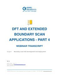
Figure 1: Bed-of-Nails vs. “Electrical-Nails” (<strong>Boundary</strong> <strong>Scan</strong>)<br />
Soon, there were ideas about how the costs of test could be reduced by more universal approaches, e.g. by using the<br />
same bed-of-nail adapter for different test units. However, the technology of the component manufacturers rapidly<br />
developed, resulting in more and more gates placed onto the silicon die; nowadays entire systems are implemented<br />
within one integrated circuit. These systems still have to communicate with the environment, though, requiring the<br />
component to be equipped with pins. With drastically increased functional density of a circuit, the number of its pins<br />
inevitably has to rise, too. Sometimes simple laws of geometry become evident: room to put all necessary pins on the<br />
device package is getting scarce. The only way out is to reduce the space between the pins. So-called "fine-pitch<br />
packages" with a space of 0.3 mm between the pins are the standard today; technologies such as BGA (ball-gridarray)<br />
or those that completely dispense with the casing - such as COB (chip on board) – are used more and more.<br />
However, these new package technologies and the connection density that comes with them cause trouble for bedof-nail<br />
fixture based testers. For if the raster of the connections gets narrower, then inevitably the probes of the bedof-nails,<br />
too, have to be placed closer to each other. Yet, there are physical limits to this. Although, a possible way out<br />
of the dilemma, distributing test pads over the board is advantageous for the adaptation, it works against the purpose<br />
of saving space through highest integration. Here the idea of BOUNDARY SCAN comes in. <strong>Boundary</strong> <strong>Scan</strong> basically<br />
means to "get rid of the external test probe" (Fig.1). <strong>Boundary</strong> <strong>Scan</strong> is replacing the external probes of a test fixture<br />
with device-internal ones, the so-called "<strong>Electronic</strong> nails", being installed at the periphery of the functional silicon (on<br />
the device boundary).<br />
GOEPEL <strong>Electronic</strong>s<br />
Application Note" 1
The development of a new test methodology<br />
To eliminate manufacturing faults, their sources have to be revealed. In order to achieve this, the stimulation and<br />
evaluation of the circuit nodes has proven to be effective. Manufacturers of integrated circuits pioneered the development<br />
of "scan procedures". Well known is LSSD (Level Sensitive <strong>Scan</strong> Design) which was introduced by IBM in the<br />
1960s. The basic idea is the division of digital circuits into combinatorial and sequential (typically flip-flops) circuit<br />
parts. The functional flip-flops are extended so that they can be used as shift registers in test mode. Test vectors can<br />
now be loaded into these shift registers and thus the flip-flops become access points to circuit nodes that can be<br />
stimulated and observed. The test of the combinatorial circuit parts can be executed through these circuit nodes,<br />
which are tested implicitly at the same time. As sequential logic is part of many integrated circuits, the test of peripheral<br />
circuitry had to be executed using external test resources rather than the shift registers mentioned above - until<br />
<strong>Boundary</strong> <strong>Scan</strong> was invented. It picks up the principle of flip-flops being connected to a shift register, yet this register<br />
is implemented into the silicon at the boundary of the circuit for the sole purpose of test access. For these flip-flops<br />
(<strong>Boundary</strong> <strong>Scan</strong> Cells) would impair the normal functioning of the circuit, they are connected to or disconnected from<br />
device pins and functional core via multiplexers. The basic functions of this architecture are:<br />
to capture test result vectors into the <strong>Boundary</strong> <strong>Scan</strong> cells,<br />
to serially shift in new test vectors and simultaneously shift out test result vectors that were captured,<br />
to apply a test vector previously shifted in to the circuitry to be tested,<br />
Test/stimulation of the inside of the integrated circuit (internal test), and<br />
Test/stimulation of outside signals being connected to the integrated circuit (external test).<br />
An integrated circuit featuring this <strong>Boundary</strong> <strong>Scan</strong> capability has to be told which actions to carry out and it has to be<br />
synchronized with other <strong>Boundary</strong> <strong>Scan</strong> capable devices on the Unit Under Test (UUT). Thus, beside the actual test<br />
vectors it has to be provided with test instructions. For the purpose of providing the test instructions as well as test<br />
vectors and for synchronization between <strong>Boundary</strong> <strong>Scan</strong> capable components (short: B<strong>Scan</strong> components) a test interface<br />
is required. In order to define such an interface and to standardize the <strong>Boundary</strong> <strong>Scan</strong> circuitry, a group of<br />
more than 200 members consisting of the leading manufacturers of integrated circuits, suppliers of test systems and<br />
manufacturers of electronic products came together to form the Joint European Test Action Group, later the Joint Test<br />
Action Group (<strong>JTAG</strong>). This group defined a four-wire test bus which optionally may be supplemented with a fifth test<br />
reset line. In order to make this test bus interface and the <strong>Boundary</strong> <strong>Scan</strong> test methodology a success as a platform<br />
which is independent from the manufacturer, it was proposed to the IEEE for standardization and eventually was approved<br />
as IEEE 1149.1 standard in 1990. Several extensions have been made since, with the latest having been approved<br />
in 2001. There has been work to complement the testability achieved by IEEE 1149.1. One working group<br />
developed an analog test bus interface for mixed signal test applications – standardized as IEEE 1149.4, approved in<br />
1999. Another working group developed a multi drop test bus interface for test on system level, known as 1149.5 (although,<br />
this standard has not been adopted widely in the industry). The latest developments in high speed interconnects<br />
on board and system level initialized work on a test methodology for AC coupled and differential interconnects<br />
based on the 1149.1 test bus protocol. Work began in May 2001, was finalized in late 2002, with standardization as<br />
IEEE 1149.6 in January 2003. Newer IEEE standards related to IEEE 1149.1 include IEEE 1149.7 and IEEE 1581.<br />
And there are ongoing efforts today, extending the principles of IEEE 1149.1 to new applications and capabilities (e.g.<br />
IEEE P1838, IEEE P1149.8.1, IEEE P1687, S<strong>JTAG</strong>).<br />
GOEPEL <strong>Electronic</strong>s<br />
Application Note" 2
The <strong>JTAG</strong> / <strong>Boundary</strong> <strong>Scan</strong> Architecture<br />
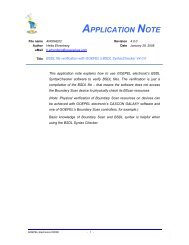
The fundamental components of the <strong>Boundary</strong> <strong>Scan</strong> architecture are the TAP (Test Access Port) and the <strong>Boundary</strong><br />
<strong>Scan</strong> register made up of <strong>Boundary</strong> <strong>Scan</strong> Cells (Fig. 2).<br />
The TAP is constructed as a finite state machine (Fig. 3)<br />
with 16 states. The transition from one state to another<br />
always occurs with the rising edge of TCK, with the level<br />
on TMS selecting the next state. The whole <strong>Boundary</strong><br />
<strong>Scan</strong> structure must be implemented as synchronous<br />
design according to the standard. After power on of the<br />
device or after the TAP is forced into the reset state the<br />
<strong>Boundary</strong> <strong>Scan</strong> structure is inactive. Besides the <strong>Boundary</strong><br />
<strong>Scan</strong> Register (BSR) an IEEE 1149.1 compliant device<br />
also contains an Instruction Register (IR) and a Bypass<br />
Register (BPR). The IR is used to define the test mode<br />
(e.g. Sample, Extest, Bypass, etc.). The purpose of the<br />
BPR is to shorten the scan chain. Other optional data<br />
registers may be implemented, such as an Identification<br />
Register.<br />
Figure 2: <strong>Boundary</strong> <strong>Scan</strong> device<br />
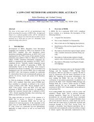
Figure 3: Test Access Port (TAP) State Machine (as defined in IEEE 1149.1)<br />
GOEPEL <strong>Electronic</strong>s<br />
Application Note" 3
To distinguish whether data or an instruction is shifted, the TAP state machine has two separate paths featuring similar<br />
states (e.g. <strong>Scan</strong> DR / <strong>Scan</strong> IR). The states most essential for the test operation are the shifting of test data<br />
(Shift DR), the capturing of data into the register (Capture DR), the delivery of the test data to the output latches of<br />
the scan cells (Update DR) as well as the analogous states for the instruction register (Shift IR, Capture IR, Update<br />
IR).<br />
As can be seen in Fig. 3, the transition from one state to another depends on the logic value on TMS. TMS (Test<br />
Mode Select) is one of the four signals that are also referred to as the Test Bus, or TAP interface, or <strong>JTAG</strong> pins. The<br />
TAP (Test Access Port) is a state machine synchronized by the Test Clock (TCK). The two other mandatory signals of<br />
the Test Bus are used for the test data transmission: Test Data In (TDI) and Test Data Out (TDO). /TRST (Test Reset,<br />
low active) is the only optional signal defined for the IEEE 1149.1 compliant Test Bus.<br />
Beside the <strong>Boundary</strong> <strong>Scan</strong> Register (BSR), the standard specifies the existence of at least a Bypass Register (BPR)<br />
as additional data register. The BPR bypasses the BSR and thus shortens the scan chain by providing a 1 cell connection<br />
between TDI and TDO of the device. The data register between TDI and TDO of a device is selected by the<br />
instruction previously scanned into the Instruction Register.<br />
The basic functions of the <strong>Boundary</strong> <strong>Scan</strong> architecture<br />
1. Parallel capture of test result vectors into the <strong>Boundary</strong> <strong>Scan</strong> cells (capture)<br />
2. Serial shifting in of test vectors and simultaneous shifting out of captured test results (shift)<br />
3. Parallel connection of loaded test vectors to the circuit node that has to be tested (update)<br />
4. Test / stimulation of the internal connections of an integrated circuit (internal test)<br />
5. Test / stimulation of pin connections on a board- or system-level circuit (external test)<br />
The <strong>Boundary</strong> <strong>Scan</strong> Cells<br />
<strong>Boundary</strong> <strong>Scan</strong> cells are available in various types, their functionality depending on whether they are used for example<br />
to capture test results only (capture cells) or both to capture test results and to apply test stimulations. Fig. 4<br />
shows examples of <strong>Boundary</strong> <strong>Scan</strong> cells: BC_1 is a unidirectional <strong>Scan</strong> cell used at inputs or outputs; BC_7 is a bidirectional<br />
scan cell. Details of cell type BC_1 are explained in the following.<br />
The Capture Flip-Flop (FF) is clocked by the broadcast signal CLOCK_DR (from TAP controller) and captures data<br />
either from the previous scan cell (shift register mode) or the parallel input (pin or core logic). The shadow latch (or<br />
Update FF) takes over the data from the Capture FF after shifting, controlled by the broadcast signal UPDATE_DR<br />
(from TAP controller). The level of the MODE signal determines whether the value in the Update FF is transferred to<br />
the cell output (test mode) or not (operational mode).<br />
Since the control signals (such as MODE, SHIFT_DR, UPDATE_DR and CLOCK_DR) are connected to all scan cells<br />
as broadcast signals, all cells within a <strong>Boundary</strong> <strong>Scan</strong> register are in the same mode at any given time. This means<br />
that all cells capable of capturing input data do so simultaneously with the rising edge on the CLOCK_DR in TAP<br />
state CAPTURE DR. Respectively, test data previously scanned into the cell is loaded in the Update FF and driven<br />
out with the falling edge on UPDATE_DR in TAP state UPDATE DR (for scan cells supporting that mode). Controlled<br />
by the signal MODE, and depending on the instruction loaded for the device (in the Instruction Register), all scan<br />
cells are either in functional mode (Parallel In connected to Parallel Out) or in test mode (Update FF connected to<br />
Parallel Out).<br />
GOEPEL <strong>Electronic</strong>s<br />
Application Note" 4
Figure 4: <strong>Boundary</strong> <strong>Scan</strong> Cells - BC_1 (top) and BC_7 (bottom)<br />
Overview of often used scan cell types<br />
1. Universal cells with two multiplexers as well as capture- and shadow latch (supports capture and update)<br />
2. Capture cells with one multiplexer and capture latch (supports only capture, e. g. as clock cell)<br />
3. Update cell with one multiplexer, capture- and shadow latch (supports only the stimulation/update)<br />
4. Checked output cells (the same as universal cells but samples Parallel Out rather than Parallel In)<br />
5. Tri-State outputs (two-cell architecture for data output and disabling)<br />
6. Bi-directional cell type A (two-cell architecture for disabling and data cell)<br />
7. Bi-directional cell type B (three-cell architecture for disabling and data cells for input and output)<br />
8. Internal cells with no connection to physical pin (typically update cells, e. g. for disabling)<br />
Standard instructions and often used optional instructions<br />
1. Mandatory instruction BYPASS:" - Bypass Register is put between TDI - TDO<br />
- Component is in functional mode<br />
2. Mandatory instruction SAMPLE:" - <strong>Boundary</strong> <strong>Scan</strong> Register is put between TDI -TDO<br />
- Component is in functional mode<br />
3. Mandatory instruction PRELOAD:" - <strong>Boundary</strong> <strong>Scan</strong> Register is put between TDI -TDO<br />
- Component is in functional mode<br />
4. Mandatory instruction EXTEST:" - <strong>Boundary</strong> <strong>Scan</strong> Register is put between TDI - TDO<br />
- Component is in test mode<br />
5. Optional instruction IDCODE:" - 32-bit Identification Register is put between TDI - TDO<br />
- Component is in functional mode<br />
The <strong>Boundary</strong> <strong>Scan</strong> features implemented in a compliant device are described in a BSDL (<strong>Boundary</strong> <strong>Scan</strong> Description<br />
Language) file, which uses a subset of VHDL syntax. BSDL is defined as part of IEEE 1149.1.<br />
GOEPEL <strong>Electronic</strong>s<br />
Application Note" 5
Test Bus Connection at Module- / Board-Level<br />
In order to use <strong>Boundary</strong> <strong>Scan</strong> at board or system level, the Test Access Ports of the involved devices need to be<br />
connected. This connection can be realized as:<br />
daisy chain configuration (Fig. 5);<br />
parallel / star configuration; or<br />
a mix of both.<br />
In case the chain configuration is selected (most common), less space on the board is needed for signal routing as<br />
TDO and TDI are connected in serial. TCK and TMS are connected in parallel to all components involved.<br />
In parallel/star configuration, individual scan chains are controlled by separate TMS and/or TCK signals. The advantage<br />
of this architecture is that in case there is a defective scan chain the others remain usable. However, the downside<br />
is the additional real estate on the board required for test signal routing. Therefore, the parallel/star architecture<br />
should only be chosen for very extensive designs or in case of special partitioning requirements. Special test bus<br />
routing devices (e.g. SCANBridge from National Semiconductors, or <strong>Scan</strong> Path Linker and Addressable <strong>Scan</strong> Port<br />
from Texas Instruments) are available for multi-drop and hierarchical scan chain designs, splitting a primary test bus<br />
into multiple secondary scan chains.<br />
Digital<br />
Core<br />
Logic<br />
Digital<br />
Core<br />
Logic<br />
/TRST<br />
TDI<br />
TCK<br />
TMS<br />
ID Reg<br />
IR<br />
BP<br />
TAP<br />
Controller<br />
TDO<br />
/TRST<br />
TDI<br />
TCK<br />
TMS<br />
ID Reg<br />
IR<br />
BP<br />
TAP<br />
Controller<br />
TDO<br />
/TRST<br />
TDI<br />
TCK<br />
TMS<br />
TDO<br />
Figure 5: <strong>Boundary</strong> <strong>Scan</strong> Chain<br />
Hierarchical Test Bus Structures<br />
One of the major advantages of <strong>Boundary</strong> <strong>Scan</strong> is that it simplifies system level interconnect test dramatically. Using<br />
this technology, connections between boards plugged into a backplane or between motherboard and daughter-cards<br />
can be verified easily. System level test often requires scan chain reconfiguration, though. Especially for backplane<br />
test, the test vectors have to be loaded into or read from the boards involved one at a time. Thus, the scan chains on<br />
these boards need to be addressable. Most of the time, system level <strong>Boundary</strong> <strong>Scan</strong> test requires a star configuration<br />
GOEPEL <strong>Electronic</strong>s<br />
Application Note" 6
of multiple scan chains (one or more scan chains on each board connected in parallel to the B<strong>Scan</strong> controller). Thus,<br />
the B<strong>Scan</strong> controller has to designate the test vectors sent to one of the scan chains. To do this, off-the-shelve addressable<br />
scan router devices are available as well as IP (Intellectual Property) cores for implementation into ASIC<br />
and PLD components. An example for a system level scan chain configuration is given in Fig. 6 below.<br />
Figure 6: System-Level <strong>Scan</strong> Chain Configuration (SRD = <strong>Scan</strong> Router Device)<br />
Process of a scan for the purpose of I/O interconnect test after power-on / reset:<br />
1. Loading B<strong>Scan</strong> instruction PRELOAD (preload function may be part of SAMPLE instruction)<br />
(addressing the <strong>Boundary</strong> <strong>Scan</strong> Register, keeps device in functional mode);<br />
2. Preload safe values and the first test vector<br />
(simultaneous shifting out of contents of scan cells, to be disregarded);<br />
3. Loading B<strong>Scan</strong> instruction EXTEST (addressing the <strong>Boundary</strong> <strong>Scan</strong> Register, transition into test mode);<br />
The first test vector (previously loaded) appears at the output pins;<br />
4. Transition to TAP state CAPTURE DR and then SHIFT DR;<br />
5. The first response/result vector sampled at the input pins in CAPTURE DR is shifted out step by step (in SHIFT DR)<br />
clocked by TCK with TMS=0; simultaneously the second test vector is shifted in;<br />
6. Transition to TAP state UPDATE DR;<br />
7. The second test vector appears at the output pins with the falling TCK edge in UPDATE DR;<br />
8. Repeat steps 4 through 7 for further test vectors (+ 1 last shift, in order to shift out the last result);<br />
GOEPEL <strong>Electronic</strong>s<br />
Application Note" 7
Built-In Self Test<br />
Built-In Self Test becomes more popular these days, with device level implementations becoming more and more<br />
complex. SOC (System-On-Chip) applications implementing several CPU, DSP, Logic and Memory blocks on the<br />
same die are not uncommon today. To test these circuits efficiently, device internal test access is required. Furthermore,<br />
it becomes more and more important to test at least a few segments of modern circuits at speed. <strong>Boundary</strong><br />
<strong>Scan</strong> does not provide for at-speed testing. However, the TAP defined in IEEE 1149.1 can be used to access internal<br />
test structures. Such internal test structures could be used to stimulate and/or observe parts of the circuitry implemented<br />
in an IC or they may even provide access to circuitry outside that device. A test utilizing these internal test<br />
structures is called a Built-In Self Test (BIST). Typically, the BIST circuitry is accessed through the TAP, initiated by a<br />
previously loaded BIST instruction. Fig. 7 below shows a sample implementation of BIST circuitry for on-chip memory<br />
and logic blocks.<br />
Figure 7: Access to Built-In Self Test (BIST) resources<br />
GOEPEL <strong>Electronic</strong>s<br />
Application Note" 8
Test Tools<br />
By now, most readers will agree that <strong>Boundary</strong> <strong>Scan</strong> is a powerful technology for mastering the test problems discussed<br />
in the introduction of this document. However, it is also clear that applying the <strong>Boundary</strong> <strong>Scan</strong> technique requires<br />
the command of the IEEE 1149.1 compliant test bus. It is not enough to provide test data or to read them out,<br />
but the TAP state machine has to be controlled as well. The attempt to control the TAP manually may well be successful;<br />
however, an effective test will hardly be possible. That is why tools relieving the user from the responsibility to<br />
control the <strong>Boundary</strong> <strong>Scan</strong> test bus and the TAP state machine have been introduced to the market very early. The<br />
user needs to focus on his test problem and he/she wants to describe test vectors the same way he/she has been<br />
used to with in-circuit or functional testers. Nowadays, the test program actually is generated automatically, based on<br />
CAD data. BSDL files provided by the device vendors provide the necessary information about the test features implemented<br />
in a <strong>Boundary</strong> <strong>Scan</strong> compliant device.<br />
GÖPEL electronic has focused on these demands from the beginning, providing one of the most comprehensive,<br />
flexible, and user friendly <strong>Boundary</strong> <strong>Scan</strong> test systems available, known as SYSTEM CASCON.<br />
In <strong>Boundary</strong> <strong>Scan</strong> test, software plays the most important role. Yet, the test methodology obviously requires hardware<br />
to apply the test vectors to the unit under test (UUT). GÖPEL electronic provides a broad portfolio of <strong>Boundary</strong> <strong>Scan</strong><br />
controllers for PC based (PCI, PCI Express, USB, Fast-Ethernet, Firewire) as well as PXI, PXI Express, LXI, and VXI<br />
based test systems.<br />
Test coverage and testability can be improved using external I/O modules that connect to otherwise not fully testable<br />
<strong>Boundary</strong> <strong>Scan</strong> nets on the UUT (e.g. through edge connectors). Here, GÖPEL electronic offers the widest selection<br />
of I/O modules and <strong>Boundary</strong> <strong>Scan</strong> accessories available on the market (e.g. CION modules, SCANFLEX I/O modules,<br />
and VarioCORE IP).<br />
<strong>Boundary</strong> <strong>Scan</strong> test systems often are used as stand-alone tools. However, a combination of <strong>Boundary</strong> <strong>Scan</strong> with In-<br />
Circuit Test, Functional Test, Flying Probe Test and even Automated Optical Inspection systems may make sense as<br />
significantly higher fault coverage can be achieved.<br />
The application of <strong>Boundary</strong> <strong>Scan</strong> is not limited to the board level. No other test procedure provides better possibilities<br />
for standardized, hierarchical test access than <strong>Boundary</strong> <strong>Scan</strong>, which can be used on component level, board<br />
level as well as on system level. Even remote test and diagnosis is possible.<br />
However, not only testing is made easier or in same cases even made possible with <strong>Boundary</strong> <strong>Scan</strong>. Tasks that have<br />
nothing to do with testing can be simplified by utilizing the IEEE 1149.1 test access port. For instance, using the TAP<br />
to program PLD and FPGA devices and the <strong>Boundary</strong> <strong>Scan</strong> approach to program EEPROM devices soldered on the<br />
module/board is very popular.<br />
GOEPEL <strong>Electronic</strong>s<br />
Application Note" 9
Test applications utilizing IEEE 1149.1<br />
Figure 8: Typical <strong>JTAG</strong>/<strong>Boundary</strong> <strong>Scan</strong> applications<br />
IEEE 1149.1 can be utilized for a variety of test, debug, and in-system programming applications.<br />
<strong>JTAG</strong>/<strong>Boundary</strong> <strong>Scan</strong> Infrastructure Test<br />
Infrastructure (or <strong>Scan</strong> Chain Integrity) Test is used to ensure that the right B<strong>Scan</strong> components are mounted and that<br />
the test resources and the scan chain(s) are accessible and functioning. This test verifies the <strong>Boundary</strong> <strong>Scan</strong> resources<br />
(register lengths and capture codes for ID-Code, Bypass, Instruction, and <strong>Boundary</strong> <strong>Scan</strong> Registers) of and<br />
the test bus connections between the various B<strong>Scan</strong> devices on the UUT.<br />
Interconnect Test<br />
The Interconnect (or Interconnections, or Connectivity) Test verifies the connections between <strong>Boundary</strong> <strong>Scan</strong> pins.<br />
The existence of serial resistors and pull-resistors is verified as well as the function and connectivity of transparent<br />
clusters (e.g. buffer devices between B<strong>Scan</strong> components). It includes test steps to find stuck-at-0 faults, stuck-at-1<br />
faults, opens and shorts, and provides diagnostic information on B<strong>Scan</strong> cell, pin and net level. During the Interconnect<br />
Test, <strong>Boundary</strong> <strong>Scan</strong> devices involved in the test are typically in EXTEST mode. The testability of a B<strong>Scan</strong> net<br />
depends heavily on the boundary scan resources available in this net and on additional non-B<strong>Scan</strong> pins connected to<br />
it. B<strong>Scan</strong> nets featuring bi-directional B<strong>Scan</strong> pins are tested in both directions, if possible.<br />
The number of test vectors (scan cycles) generated depends on the number of B<strong>Scan</strong> nets and on the highest number<br />
of B<strong>Scan</strong> drivers found in any B<strong>Scan</strong> net. Several test steps are generated: first stuck-at-low and stuck-at-high<br />
!<br />
GOEPEL <strong>Electronic</strong>s<br />
Application Note" 10
tests, then one or more “counter tests” to find shorts and opens. For stuck-at test, the maximum number of B<strong>Scan</strong><br />
drivers in any one net is defining the total number of generated test vectors. For counter tests, the number of generated<br />
test vectors can be calculated per logarithm of the number of nets to the basis two. Specific UUT requirements<br />
may increase or decrease the number of test vectors.<br />
The Interconnect Test may include IEEE 1149.4 and IEEE 1149.6 compliant networks on the Unit Under Test.<br />
Memory Access Test<br />
A Memory Access (or Memory Cluster) Test verifies the connections between <strong>Boundary</strong> <strong>Scan</strong> pins and the memory<br />
device (at the same time other B<strong>Scan</strong> to B<strong>Scan</strong> pin connections are checked as well). Existence of serial resistors<br />
and pull-resistors is verified. The function of the memory devices and any logic between B<strong>Scan</strong> device and the memory<br />
devices is also tested (although typically at slower speed than functional access).<br />
➡ Access to all memory control pins is required (direct or indirect).<br />
➡ Control over clock signals on SDRAM, and similar devices, is required.<br />
Logic Cluster Test<br />
A Logic Cluster Test verifies the connections from <strong>Boundary</strong> <strong>Scan</strong> pins to Cluster inputs and outputs and connections<br />
within the cluster as well as the general cluster functionality. Fault isolation is limited due to missing <strong>Boundary</strong> <strong>Scan</strong><br />
access to all cluster-internal nodes.<br />
➡ Keep logic clusters as small as possible.<br />
➡ Control over non-B<strong>Scan</strong> devices and clock signals (for sequential logic) is required.<br />
In-System Programming of CPLD<br />
Most modern programmable logic devices (PLD) provide a IEEE-1149.1 test bus interface and support in-system<br />
programming (ISP) through that port. Typically, programming control is built in to the device and the control sequence<br />
and programming data is provided by means of various file types, such as SVF files, JAM files, STAPL (Jedec-Std.<br />
71) files, or IEEE 1532 files.<br />
In-System Programming of EEPROM<br />
Flash devices and other EEPROM (such as serial EEPROM based on I2C or SPI protocol) can be programmed via<br />
<strong>Boundary</strong> <strong>Scan</strong> devices if access is available to all memory pins required for programming (either directly or indirectly).<br />
To reduce programming time, a short scan chain and high TCK frequency are required.<br />
➡ Separate the B<strong>Scan</strong> device used to program EEPROM from other B<strong>Scan</strong> devices (put it in a separate scan<br />
chain) if those devices support only a much slower TCK frequency.<br />
➡ Try to control all EEPROM pins from the same B<strong>Scan</strong> component (so that all other B<strong>Scan</strong> components can be<br />
kept in HIGHZ, CLAMP, or BYPASS mode).<br />
➡ Programming speed can be increased if frequently exercised control pins (such as /WE) are accessed with<br />
parallel I/O resources rather than <strong>Boundary</strong> <strong>Scan</strong>. Precondition for that is that the <strong>Boundary</strong> <strong>Scan</strong> pin in the<br />
respective net can be disabled and that access to the control pin is available via connector (preferably) or test<br />
pad.<br />
!<br />
GOEPEL <strong>Electronic</strong>s<br />
Application Note" 11
Built-In Self Test (Device Test / Emulation)<br />
Built-In Self Test (BIST) can be used to verify that a device is working properly after it has been assembled on a PCB.<br />
Usually, BIST is used to exercise device functions at speed. The test can be initiated via the IEEE-1149.1 test bus<br />
interface, e.g. by loading a BIST data register with stimulus applying the RUNBIST instruction. After completion, the<br />
test results (e.g. a signature pattern) can be read out via the test bus interface.<br />
In a similar way, device emulation resources can be accessed through the test bus interface to debug device functions<br />
and/or firmware programmed into a device.<br />
➡ Keep the device to be tested in a separate scan chain if the tool used to apply BIST pattern or emulation sequences<br />
cannot handle devices other than the target component in the same scan chain.<br />
Extended Interconnect Test<br />
Often times, <strong>Boundary</strong> <strong>Scan</strong> alone cannot test all of the board level circuitry completely. Usually, other test methodologies,<br />
such as MDA (Manufacturing Defect Analysis), AOI (Automatic Optical Inspection), ICT (In-Circuit Test), or FT<br />
(Functional Test), are used to complement <strong>Boundary</strong> <strong>Scan</strong> to achieve satisfactory test coverage. Executing all these<br />
tests in a separate step means board handling overhead that may be reduced by combining test methods.<br />
<strong>Boundary</strong> <strong>Scan</strong> can be highly advantageous when integrated into ATE systems based on a bed-of-nails or moving<br />
probes (Flying Probe Testers). A combined solution can either reduce the number of nails required in a fixed-probeadapter<br />
(thus dramatically reduce adapter cost), or it can improve the test time by reducing the number probing points<br />
required for an interconnect test based on moving probes.<br />
Combined <strong>Boundary</strong> <strong>Scan</strong> - Functional Test<br />
Combining Ad-Hoc test, such as FT (Functional Test), with <strong>Boundary</strong> <strong>Scan</strong> has the advantage, that functional test<br />
sequences become much simpler, since they donʼt have to detect and locate/diagnose structural faults. <strong>Boundary</strong><br />
<strong>Scan</strong> tests can be initiated at the beginning of the test sequence, verifying that there are no structural faults on the<br />
Unit Under Test (UUT) in the circuitry testable via <strong>Boundary</strong> <strong>Scan</strong> resources. After successful execution of the<br />
<strong>Boundary</strong> <strong>Scan</strong> tests, functional tests can be run to exercise the UUT at speed. <strong>Boundary</strong> <strong>Scan</strong> can be used to reconfigure<br />
certain parts of the circuitry, e.g. to aid functional test or to load the firmware. At the most integrated level,<br />
both <strong>Boundary</strong> <strong>Scan</strong> resources and functional test resources can be used in conjunction to improve testability and<br />
simplify test sequences.<br />
Interlaced Emulation and <strong>Boundary</strong> <strong>Scan</strong> Test<br />
Introduced by GOEPEL as part of the VarioTAP technology, Interlaced Emulation (and <strong>Boundary</strong> <strong>Scan</strong>) Test utilizes<br />
on-chip emulation resources accessible in many micro-processors (μP) and micro-controllers (μC) through an IEEE<br />
1149.1 compatible <strong>JTAG</strong> Port, in conjunction with <strong>Boundary</strong> <strong>Scan</strong> registers in other devices on the Unit Under Test<br />
(UUT), in order to enhance the overall test coverage. Acting as an intelligent test controller at the functional core of<br />
the UUT, accessed via its <strong>JTAG</strong> port, the μP/μC generates dynamic test sequences that interact with <strong>Boundary</strong> <strong>Scan</strong><br />
cells in other devices on the UUT (in an interlaced way), essentially providing virtual test points (virtual probes).<br />
Supporting a real fusion of functional test via <strong>JTAG</strong> Emulation and structural test via <strong>Boundary</strong> <strong>Scan</strong>, VarioTAP redefines<br />
the concept of Extended <strong>JTAG</strong>/<strong>Boundary</strong> <strong>Scan</strong>, allowing the user to create procedures for:<br />
➡ Structural test applications,<br />
➡ Functional test applications,<br />
!<br />
GOEPEL <strong>Electronic</strong>s<br />
Application Note" 12
➡ Structural functional test,<br />
➡ Diagnostic test applications, and<br />
➡ Custom applications<br />
Generic !P / MCU / CPU model (On-Chip Resources)<br />
PCI-Express,<br />
CAN, LIN, FlexRay,<br />
BlueTooth, WLAN,<br />
USB, LAN,<br />
RS232, ...<br />
Bus I/F<br />
Type A<br />
Bus I/F<br />
Type X<br />
Flash<br />
Core<br />
Analog I/O<br />
Digital I/O<br />
Audio, Video,<br />
Legacy analog,<br />
Legacy digital,<br />
PWM signals,<br />
I2C, SPI, !W, ...<br />
Internal<br />
Circuits<br />
System<br />
Bus I/F<br />
Mixed I/O<br />
On-Board Resources: DRAM, External Periphery, Bridges, etc.<br />
Application Type A:<br />
Programming Functions for<br />
On-Chip / external Flash<br />
Application Type B:<br />
Bus Control Functions for<br />
Bus Emulation Test<br />
Application Type C:<br />
Test Control Functions for<br />
On-Chip Resources<br />
Figure 9: Extended test applications based on <strong>JTAG</strong>/<strong>Boundary</strong> <strong>Scan</strong> access, enabled by VarioTAP technology<br />
!<br />
GOEPEL <strong>Electronic</strong>s<br />
Application Note" 13
Other standards related to IEEE 1149.1<br />
IEEE 1149.1 provides a foundation other standards have been building on and ongoing standardization efforts continue<br />
to exploit and improve upon.<br />
Figure 10: Timeline of IEEE 1149.1 and related standards<br />
IEEE 1149.4<br />
Approved in 1999, IEEE 1149.4 defines test resources and test access for mixed-signal <strong>Boundary</strong> <strong>Scan</strong> Test. The<br />
purpose of this standard is to provide the means to measure and characterize device level or board level mixedsignal<br />
and analogue parameters. IEEE 1149.4 compliant devices (which are also 1149.1 compliant) feature two additional<br />
test bus signals (AT1 and AT2). These two test bus signals can be connected to I/O pins through a switching<br />
structure (TBIC and ABM) for the purpose of test. Typically, they are used to provide a constant current to one pin and<br />
to measure the voltage on that and another pin. This test approach is used to measure resistance and capacities in<br />
the circuitry. Figure 11 provides a simple overview of what an IEEE 1149.4 compliant device could look like.<br />
Figure 11: Test features of an IEEE 1149.4 device<br />
!<br />
GOEPEL <strong>Electronic</strong>s<br />
Application Note" 14
IEEE 1149.6<br />
Work on a new standard (based on IEEE 1149.1) to test AC-coupled and other advanced I/O networks has been initiated<br />
in May 2001. Since <strong>Boundary</strong> <strong>Scan</strong> (IEEE 1149.1) provides for quasi-static structural test only, device, board or<br />
system level nets coupled through in-line capacitors cannot be tested with that approach. A more dynamic test circuitry<br />
was required to provide a high-speed signal that propagates through such AC coupled networks. The scope of<br />
work for the P1149.6 working group was to define <strong>Boundary</strong> <strong>Scan</strong> output cells and AC test signal generation as well<br />
as test receivers, and to specify the timing parameters required for a successful test of AC coupled networks.<br />
IEEE 1149.6, approved in 2003, defines the <strong>Boundary</strong> <strong>Scan</strong> structures and test instructions of compliant devices as<br />
well as the BSDL syntax used to describe these features. Figure 12 shows an implementation of a <strong>Boundary</strong> <strong>Scan</strong><br />
output cell on a differential port with an AC selection cell. A sample implementation for an input <strong>Boundary</strong> <strong>Scan</strong> cell<br />
able to receive and analyze AC test signals is shown in Figure 13.<br />
Figure 12: IEEE 1149.6 compliant <strong>Boundary</strong> <strong>Scan</strong> output cell on a differential driver<br />
Figure 13: IEEE 1149.6 compliant <strong>Boundary</strong> <strong>Scan</strong> input cell on a differential receiver<br />
!<br />
GOEPEL <strong>Electronic</strong>s<br />
Application Note" 15
IEEE 1500<br />
This Standard for Embedded Core Test has been created to address the test complexity of System on Chips (SoCs)<br />
by providing a standardized test bus interface and a set of rules applied to isolate a particular core from the logic surrounding<br />
that core. The purpose of this isolation boundary (called a wrapper) is to allow the test of a core without any<br />
influence from circuitry outside the core, while keeping the amount of signals that must be brought out to the SoC<br />
level to a minimum. Similar to the <strong>Boundary</strong> <strong>Scan</strong> Register in a <strong>JTAG</strong>/<strong>Boundary</strong> <strong>Scan</strong> compliant device, the wrapper<br />
in a IEEE 1500 compliant devices comprises of wrapper cells for each functional I/O port. The wrapper cells are<br />
stringed together to form one or more wrapper scan chain(s). The wrapper cells are used to observe and stimulate<br />
the core logic they are linked to.<br />
IEEE 1532<br />
In-System Programming of PLD and FPGA is another application that utilizes the TAP defined in IEEE 1149.1. For<br />
years, different vendors of programmable devices had their own programming algorithms implemented in their device.<br />
Sometimes this caused problems when devices from different vendors where mixed within the same scan chain.<br />
With IEEE 1532 the programming algorithms for compliant devices as well as the format of programming data has<br />
been standardized for the first time. Thus, several devices (compliant with this standard) from different vendors within<br />
the same chain are now programmed using the same algorithms, simplifying programming tools and logistics. Furthermore,<br />
IEEE 1532-2002 defines the optional implementation of concurrent programming features. Concurrent programming<br />
can provide a significant improvement in programming time as more than one device can be programmed<br />
at the same time, rather than sequentially. Figure 14 outlines the principle of device programming via IEEE 1532.<br />
Figure 14: IEEE 1532 for device programming<br />
!<br />
GOEPEL <strong>Electronic</strong>s<br />
Application Note" 16
IEEE 1581<br />
Today, IEEE 1149.1 test resources are implemented in many digital circuits (such as CPUʼs, DSPʼs, PLD/FPGAʼs,<br />
interface devices, etc.). Even some memory components (e.g. some SRAM and FIFO components) have <strong>Boundary</strong><br />
<strong>Scan</strong> implemented, although some of them do not support the EXTEST capability as defined in IEEE 1149.1. However,<br />
many Memory components do not have any test resources built in. The connectivity between <strong>Boundary</strong> <strong>Scan</strong><br />
compliant components and such memory devices can only be tested by means of cluster testing (writing to the memory<br />
and reading back pattern written to the memory). This requires full access to the memory control pins, though.<br />
Many SDRAM or newer synchronous memory architectures are implemented on board level with clock circuitry that<br />
cannot be synchronized with <strong>Boundary</strong> <strong>Scan</strong>. This means that these memory structures cannot be tested via <strong>Boundary</strong><br />
<strong>Scan</strong> in cluster tests. Today, no standard test methodology for memory testing is available. One approach introduced<br />
in the late 1990ʼs was SCITT. An IEEE working group (P1581) has been formed to create a standard test<br />
methodology for memory interconnect testing. In principle, IEEE Std 1581 describes test circuitry to be implemented<br />
in a memory device that bypasses the memory block itself and instead provides a logic connection between input and<br />
output pins (using simple logic gates). By stimulating the memory input pins and observing its output pins via B<strong>Scan</strong><br />
devices connected to the memory, board level connectivity can be verified; simplifying and accelerating this kind of<br />
test dramatically. The same technology can be applied to and implemented in other slave-type components.<br />
IEEE Std 1581 has been approved in March 2011 and was published in June 2011.<br />
Figure 15: IEEE 1581 compliant device; test control via Test Mode Control logic or via optional Test Pin<br />
!<br />
GOEPEL <strong>Electronic</strong>s<br />
Application Note" 17
IEEE 1149.7<br />
The Mobile Industry Processor Interface (MIPI) Test and Debug Working group has selected a new test and debug<br />
interface, called Compact <strong>JTAG</strong> (c<strong>JTAG</strong>), which builds upon the IEEE Std.1149.1 standard. The goal of c<strong>JTAG</strong>, standardized<br />
as IEEE 1149.7, is to enable advancements in test and debug functionality while maintaining compatibility<br />
with IEEE 1149.1 by creating a superset of the IEEE 1149.1 test interface.<br />
A primary objective of c<strong>JTAG</strong> was to preserve the industryʼs hardware and software investments in this standard.<br />
With c<strong>JTAG</strong>, existing tools or Debug and Test Systems (DTS), such as an IEEE 1149.1 emulator, and Target System<br />
(TS) chips, can simply be extended with adapters to convert to the c<strong>JTAG</strong> interface.<br />
Figure 16: IEEE 1149.7 introduces a narrow (two-pin) test bus interface as well as means to access a wide variety of<br />
chip-internal test, debug, and related functions [diagram from IEEE 1149.7 working group presentation]<br />
Classes introduced and defined in IEEE 1149.7 introduce:<br />
" IEEE 1149.1 Extensions:<br />
Class T0: Assure IEEE Compliance for chips with multiple TAPs<br />
(.etc Class T1: Adding control functions (e.g. TAP power management, functional reset,<br />
Class T2: Adding performance features for series configurations<br />
Class T3: Adding performance features for star configurations<br />
" Advanced Two-Pin (test bus) Operation:<br />
Class T4: Adding two pin operation<br />
Class T5: Adding instruction/custom pin use to two pin operation<br />
!<br />
GOEPEL <strong>Electronic</strong>s<br />
Application Note" 18
IEEE P1687<br />
Also referred to as I<strong>JTAG</strong> (Internal <strong>JTAG</strong>), the IEEE P1687 working group intends to develop a methodology for access<br />
to embedded test and debug features (but not the features themselves) via the IEEE 1149.1 Test Access Port<br />
(TAP) and additional signals that may be required.<br />
The IEEE 1149.1 standard specifies circuits to be embedded within an Integrated Circuit to support board test,<br />
namely the Test Access Port (TAP), TAP Controller, and a number of internal registers. In practice, the TAP and TAP<br />
controller are being used for other functions well beyond boundary scan in an ad-hoc manner across the industry to<br />
access a wide variety of internal chip test and debug features. The purpose of the I<strong>JTAG</strong> initiative is to provide an<br />
extension to the IEEE 1149.1 standard specifically aimed at using the TAP to manage the configuration, operation<br />
and collection of data from embedded test and debug circuitry. There exists the widespread use of embedded instrumentation<br />
(such as BIST Engines, Complex I/O Characterization and Calibration, Embedded Timing Instrumentation,<br />
etc.) each of which is accessed and managed by a variety of external instrumentation using a variety of mechanisms<br />
and protocols. Therefore, there exists a need for a standardization of these protocols in order to ensure an efficient<br />
and orderly methodology for the preparation of tests and the access and control of these embedded instruments. The<br />
elements of the methodology include a description language for the characteristics of the features and for communication<br />
with the features, and requirements for interfacing to the features. [Excerpt from the IEEE P1687 PAR]<br />
Figure 17: Examples of instruments implemented and accessible (via IEEE 1149.1 TAP) in an IEEE P1687<br />
IEEE P1687 focuses on:<br />
Documentation: architectural descriptions<br />
(identify accessible embedded instruments, specify characteristics of the instrument);<br />
Access protocols: procedure descriptions<br />
(ow to communicate with an instrument, facilitate re-use through portability);<br />
“Enhanced”, secondary access/interface<br />
(Access instruments not easily handled solely by the TAP [i.e. use high bandwidth I/O],<br />
simplify hierarchical test architectures)<br />
!<br />
GOEPEL <strong>Electronic</strong>s<br />
Application Note" 19
GOEPEL <strong>Electronic</strong>s<br />
GOEPEL electronics LLC is a subsidiary of GÖPEL electronic GmbH, headquartered in Jena, Germany. GÖPEL electronic<br />
GmbH was founded in 1991 as a spin-off of Carl Zeiss Jena and has several sales support offices in Germany,<br />
in France, in the UK, in Hong Kong, and in the USA.<br />
The company is organized in three major business units:<br />
<strong>JTAG</strong>/<strong>Boundary</strong> <strong>Scan</strong> Systems<br />
Automotive Test and Functional Test Systems<br />
Automated Optical Inspection and Digital Image Processing Systems<br />
GÖPEL was one of the worldʼs first suppliers of <strong>JTAG</strong>/<strong>Boundary</strong> <strong>Scan</strong> Test Equipment. From the beginning, the company<br />
has been setting pioneering trends to widely spread the use of <strong>JTAG</strong>/<strong>Boundary</strong> <strong>Scan</strong> standard IEEE 1149.1.<br />
Today GÖPEL is in a market leading position with thousands of installed systems in active use, offering mature software<br />
tools in an integrated development environment, high-performance <strong>Boundary</strong> <strong>Scan</strong> controllers and accessories,<br />
as well as comprehensive product support and value added services for IEEE 1149.x compliant test and in-system<br />
programming applications. GÖPEL electronicʼs 170 skilled employees continually develop new and enhance existing<br />
products, generating a revenue of approximately EUR22 Million in 2010, while an extended distribution and service<br />
network of more than 300 specialists, including independent support centers, system integrators and value added<br />
resellers (VARs), ensures excellent local and on-site customer support world-wide.<br />
Product and customer services are inseparable in GÖPELʼs business philosophy. As all products are provided from<br />
one source, hardware and software tools are optimally coordinated to allow system configurations that exactly match<br />
the required performance class.<br />
The highest customer satisfaction and product quality is GÖPELʼs continuing goal. The company has continuously<br />
been ISO 9001 certified since 1996 and has been honored with TOP-JOB and TOP-100 awards for being one of the<br />
best medium-sized companies in Germany. GÖPEL electronicʼs products have won several awards, including 2004,<br />
2006, 2007, 2008, 2009, 2010, and 2011 “Best-in-Test Awards”, and are used by the leading companies in telecommunication,<br />
automotive, military, space and avionics, industrial controls, medical technology, and other industries.<br />
For further information about GÖPEL electronic and our products and services please contact us or visit us on-line at<br />
www.goepel.com and at www.goepelusa.com.<br />
!<br />
GOEPEL <strong>Electronic</strong>s<br />
Application Note" 20
Glossary<br />
ABM<br />
Analog <strong>Boundary</strong> Module<br />
AC<br />
Alternating Current<br />
ADC<br />
Analog to Digital Converter<br />
AOI<br />
Automated Optical Inspection<br />
ASIC<br />
Application-Specific Integrated<br />
Circuit<br />
ATAP<br />
Analog Test Access Port<br />
ATE<br />
Automated Test Equipment<br />
AXI<br />
Automated X-Ray Inspection<br />
BGA<br />
Ball-Grid Array<br />
BERT<br />
Bit Error Rate Test(er)<br />
BIST<br />
Built-In Self Test<br />
BPR<br />
Bypass Register<br />
BSC<br />
<strong>Boundary</strong> <strong>Scan</strong> Cell<br />
B<strong>Scan</strong><br />
<strong>Boundary</strong> <strong>Scan</strong><br />
BSR<br />
<strong>Boundary</strong> <strong>Scan</strong> Register<br />
BSDL<br />
<strong>Boundary</strong> <strong>Scan</strong> Description<br />
Language<br />
CAD<br />
Computer Aided Design [Data]<br />
CCA<br />
Circuit Card Assembly<br />
c<strong>JTAG</strong><br />
Compact <strong>JTAG</strong><br />
COB<br />
Chip On Board<br />
CPI<br />
Central Processing Unit<br />
CPLD<br />
Complex PLD<br />
DAC<br />
Digital to Analog Converter<br />
DC<br />
Direct Current<br />
DR<br />
Data Register<br />
DRAM<br />
Dynamic RAM<br />
DSP<br />
Digital Signal Processor<br />
DTS<br />
Debug and Test System<br />
EBST<br />
Embedded <strong>Boundary</strong> <strong>Scan</strong> Test<br />
EEPROM<br />
Electrically Erasable Programmable<br />
Read-Only Memory<br />
FF<br />
Flip-Flop<br />
FIFO<br />
First-In / First-Out [Memory]<br />
FPGA<br />
Field-Programmable Gate Array<br />
FPT<br />
Flying Probe Test(er)<br />
FT<br />
Functional Test(er)<br />
I2C<br />
Inter-Integrated Circuit [Bus]<br />
IEEE<br />
Institute of Electrical and <strong>Electronic</strong>s<br />
Engineers<br />
IC<br />
Integrated Circuit<br />
ICE<br />
In-Circuit Emulation<br />
ICP<br />
In-Circuit Programming<br />
ICT<br />
In-Circuit Test<br />
I/F<br />
Interface<br />
!<br />
GOEPEL <strong>Electronic</strong>s<br />
Application Note" 21
I<strong>JTAG</strong><br />
Internal <strong>JTAG</strong><br />
I/O<br />
Input/Output<br />
IP<br />
Intellectual Property<br />
IR<br />
Instruction Register<br />
ISC<br />
In-System Configuration<br />
ISP<br />
In-System Programming<br />
Jam<br />
Predecessor to STAPL<br />
<strong>JTAG</strong><br />
Joint Test Action Group<br />
μC<br />
Micro-Controller<br />
LAN<br />
Local Area Network<br />
LIN<br />
Local Interconnect Network<br />
LXI<br />
LAN Extensions for Instrumentation<br />
MCM<br />
Multi-Chip Module<br />
MCU<br />
Micro-Controller Unit<br />
MDA<br />
Manufacturing Defect Analyzer<br />
μP<br />
Micro-Processor<br />
μW<br />
Micro-Wire [Bus/Protocol]<br />
OCE<br />
On-Chip Emulation<br />
PCA<br />
Printed Circuit Assembly<br />
PCB<br />
Printed Circuit Board<br />
PCI<br />
Peripheral Component Interconnect<br />
PLD<br />
Programmable Logic Device<br />
PWM<br />
Pulse-Width Modulation<br />
PXI<br />
PXI Extensions for Instrumentation<br />
RAM<br />
Random Access Memory<br />
SDRAM<br />
Synchronous DRAM<br />
SCITT<br />
Static Component Interconnection<br />
Test Technology<br />
SOC<br />
System On Chip<br />
SIP<br />
System In Package<br />
S<strong>JTAG</strong><br />
System <strong>JTAG</strong><br />
SPI<br />
Serial Peripheral Interface [Bus]<br />
SRD<br />
<strong>Scan</strong> Router Device<br />
STAPL<br />
Standard Test And Programming<br />
Language (Jedec Std. 71)<br />
SVF<br />
Serial Vector Format<br />
TAP<br />
Test Access Port<br />
TBIC<br />
Test Bus Interface Circuit<br />
TCK<br />
Test Clock<br />
TDI<br />
Test Data Input<br />
TDO<br />
Test Data Output<br />
TMS<br />
Test Mode Select<br />
TRST<br />
Test Reset (low active)<br />
USB<br />
Universal Serial Bus<br />
UUT<br />
Unit Under Test<br />
WLAN<br />
Wireless LAN<br />
XBST<br />
External <strong>Boundary</strong> <strong>Scan</strong> Test<br />
!<br />
GOEPEL <strong>Electronic</strong>s<br />
Application Note" 22