A low cost methode for BSDL Verification - Goepel Electronic
A low cost methode for BSDL Verification - Goepel Electronic
A low cost methode for BSDL Verification - Goepel Electronic

Create successful ePaper yourself
Turn your PDF publications into a flip-book with our unique Google optimized e-Paper software.
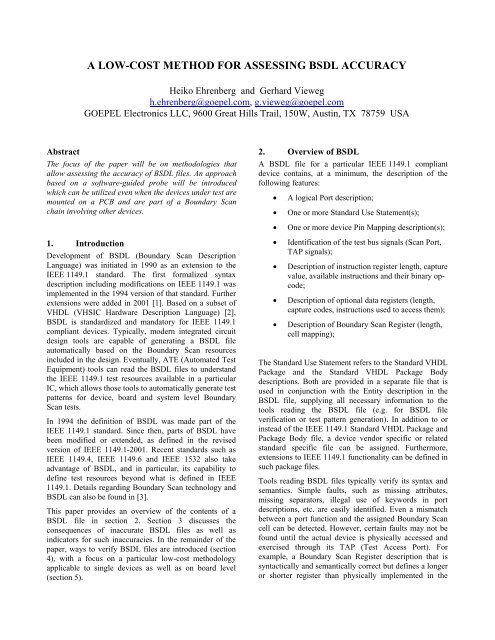
A LOW-COST METHOD FOR ASSESSING <strong>BSDL</strong> ACCURACY<br />
Heiko Ehrenberg and Gerhard Vieweg<br />
h.ehrenberg@goepel.com, g.vieweg@goepel.com<br />
GOEPEL <strong>Electronic</strong>s LLC, 9600 Great Hills Trail, 150W, Austin, TX 78759 USA<br />
Abstract<br />
The focus of the paper will be on methodologies that<br />
al<strong>low</strong> assessing the accuracy of <strong>BSDL</strong> files. An approach<br />
based on a software-guided probe will be introduced<br />
which can be utilized even when the devices under test are<br />
mounted on a PCB and are part of a Boundary Scan<br />
chain involving other devices.<br />
2. Overview of <strong>BSDL</strong><br />
A <strong>BSDL</strong> file <strong>for</strong> a particular IEEE 1149.1 compliant<br />
device contains, at a minimum, the description of the<br />
fol<strong>low</strong>ing features:<br />
• A logical Port description;<br />
• One or more Standard Use Statement(s);<br />
• One or more device Pin Mapping description(s);<br />
1. Introduction<br />
Development of <strong>BSDL</strong> (Boundary Scan Description<br />
Language) was initiated in 1990 as an extension to the<br />
IEEE 1149.1 standard. The first <strong>for</strong>malized syntax<br />
description including modifications on IEEE 1149.1 was<br />
implemented in the 1994 version of that standard. Further<br />
extensions were added in 2001 [1]. Based on a subset of<br />
VHDL (VHSIC Hardware Description Language) [2],<br />
<strong>BSDL</strong> is standardized and mandatory <strong>for</strong> IEEE 1149.1<br />
compliant devices. Typically, modern integrated circuit<br />
design tools are capable of generating a <strong>BSDL</strong> file<br />
automatically based on the Boundary Scan resources<br />
included in the design. Eventually, ATE (Automated Test<br />
Equipment) tools can read the <strong>BSDL</strong> files to understand<br />
the IEEE 1149.1 test resources available in a particular<br />
IC, which al<strong>low</strong>s those tools to automatically generate test<br />
patterns <strong>for</strong> device, board and system level Boundary<br />
Scan tests.<br />
In 1994 the definition of <strong>BSDL</strong> was made part of the<br />
IEEE 1149.1 standard. Since then, parts of <strong>BSDL</strong> have<br />
been modified or extended, as defined in the revised<br />
version of IEEE 1149.1-2001. Recent standards such as<br />
IEEE 1149.4, IEEE 1149.6 and IEEE 1532 also take<br />
advantage of <strong>BSDL</strong>, and in particular, its capability to<br />
define test resources beyond what is defined in IEEE<br />
1149.1. Details regarding Boundary Scan technology and<br />
<strong>BSDL</strong> can also be found in [3].<br />
This paper provides an overview of the contents of a<br />
<strong>BSDL</strong> file in section 2. Section 3 discusses the<br />
consequences of inaccurate <strong>BSDL</strong> files as well as<br />
indicators <strong>for</strong> such inaccuracies. In the remainder of the<br />
paper, ways to verify <strong>BSDL</strong> files are introduced (section<br />
4), with a focus on a particular <strong>low</strong>-<strong>cost</strong> methodology<br />
applicable to single devices as well as on board level<br />
(section 5).<br />
• Identification of the test bus signals (Scan Port,<br />
TAP signals);<br />
• Description of instruction register length, capture<br />
value, available instructions and their binary opcode;<br />
• Description of optional data registers (length,<br />
capture codes, instructions used to access them);<br />
• Description of Boundary Scan Register (length,<br />
cell mapping);<br />
The Standard Use Statement refers to the Standard VHDL<br />
Package and the Standard VHDL Package Body<br />
descriptions. Both are provided in a separate file that is<br />
used in conjunction with the Entity description in the<br />
<strong>BSDL</strong> file, supplying all necessary in<strong>for</strong>mation to the<br />
tools reading the <strong>BSDL</strong> file (e.g. <strong>for</strong> <strong>BSDL</strong> file<br />
verification or test pattern generation). In addition to or<br />
instead of the IEEE 1149.1 Standard VHDL Package and<br />
Package Body file, a device vendor specific or related<br />
standard specific file can be assigned. Furthermore,<br />
extensions to IEEE 1149.1 functionality can be defined in<br />
such package files.<br />
Tools reading <strong>BSDL</strong> files typically verify its syntax and<br />
semantics. Simple faults, such as missing attributes,<br />
missing separators, illegal use of keywords in port<br />
descriptions, etc. are easily identified. Even a mismatch<br />
between a port function and the assigned Boundary Scan<br />
cell can be detected. However, certain faults may not be<br />
found until the actual device is physically accessed and<br />
exercised through its TAP (Test Access Port). For<br />
example, a Boundary Scan Register description that is<br />
syntactically and semantically correct but defines a longer<br />
or shorter register than physically implemented in the
device will make the <strong>BSDL</strong> file appear correct to the ATE<br />
that doesn’t have any other reference. However, when<br />
physically accessing the Boundary Scan Register of that<br />
device, the Boundary Scan chain will appear longer or<br />
shorter, respectively, than expected, causing the<br />
Boundary Scan test to fail. Another example is a wrong<br />
order of cells in the Boundary Scan Register description.<br />
Since the Boundary Scan implementation in compliant<br />
devices becomes an essential part of the ATE during the<br />
test, it is a prerequisite that ATE tools can rely on those<br />
features being described accurately in the <strong>BSDL</strong> file.<br />
Otherwise, Boundary Scan testing cannot be<br />
accomplished successfully without lengthy debugging<br />
procedures.<br />
Years ago a group of engineers designed a tool to<br />
automatically generate a <strong>BSDL</strong> file from a physical<br />
sample device that is known to be IEEE 1149.1 compliant<br />
[4]. Such an approach can be used to either generate a<br />
<strong>BSDL</strong> file <strong>for</strong> a component <strong>for</strong> which no <strong>BSDL</strong> file exists<br />
at all, or to algorithmically extract <strong>BSDL</strong> in<strong>for</strong>mation<br />
from the physical device <strong>for</strong> comparison against an<br />
existing <strong>BSDL</strong> file.<br />
3. Consequences of <strong>BSDL</strong> inaccuracy<br />
The fol<strong>low</strong>ing paragraphs discuss mismatches between<br />
the <strong>BSDL</strong> description and the physical implementation of<br />
Boundary Scan resources in the device itself. Syntax and<br />
semantic errors shall be excluded from the discussion, as<br />
those are typically identified by the ATE’s <strong>BSDL</strong> parser<br />
reading the file.<br />
3.1. How do mismatches between <strong>BSDL</strong> and silicon<br />
affect Boundary Scan tests?<br />
Table 1 shows a few examples of possible mismatches<br />
between the <strong>BSDL</strong> description and the implementation of<br />
the Boundary Scan resources on the silicon.<br />
Some of these faults, or a combination of several of them,<br />
may even result in board level conflicts during test, which<br />
can cause the scan chain to break, e.g. due to a test bus<br />
reset.<br />
Many of the faults created by <strong>BSDL</strong> inaccuracies such as<br />
those mentioned in table 1 could also be the result of<br />
mistakes made during test development or during the<br />
Design-For-Testability [5] process. Assuming the <strong>BSDL</strong><br />
files are correct, out-of-date CAD data, bad device<br />
models <strong>for</strong> non-Boundary-Scan components, Ground-<br />
Bounce effects [6], disregarded compliance pattern, etc.<br />
could cause similar faults during board and system level<br />
test execution. This makes it even harder to gain<br />
confidence in the Boundary Scan implementation if there<br />
is no assurance about the correctness of the <strong>BSDL</strong> files<br />
used. The goal should be only to use devices whose<br />
<strong>BSDL</strong> files have been verified, preferably by the device<br />
vendor, and otherwise by the user or a third-party. If<br />
<strong>BSDL</strong> files are used that have not been verified against<br />
the silicon, there is always a chance of mismatches in<br />
early versions, especially <strong>for</strong> ASIC’s. Faulty <strong>BSDL</strong> file<br />
descriptions used during test pattern generation result in<br />
Boundary Scan tests that may exercise the Device-Under-<br />
Test in unexpected ways causing false error messages at<br />
run time.<br />
3.2. How to trace problems back to a bad <strong>BSDL</strong> file?<br />
Nowadays, most <strong>BSDL</strong> files accurately reflect the<br />
Boundary Scan implementation in the device they belong<br />
to. Automated <strong>BSDL</strong> creation tools make the process of<br />
generating the file less error prone. Still, there are cases<br />
where a <strong>BSDL</strong> file does not exactly represent the features<br />
implemented on silicon, be it because of a change in the<br />
design of the device that has not been revised in its<br />
corresponding <strong>BSDL</strong> file, or because of a mistake in a<br />
manually created <strong>BSDL</strong> file.<br />
Eventually, mismatches between a <strong>BSDL</strong> file and the<br />
device it belongs to will be detected. If the Boundary<br />
Scan implementation has not been verified on the device<br />
by itself, problems will likely show up during board level<br />
testing, but it will be more time consuming to locate<br />
problems related to a <strong>BSDL</strong> description at this stage.<br />
Typically, the verification is done in multiple steps:<br />
• <strong>Verification</strong> of the Test Access Port (TAP)<br />
functionality (including Compliance Enable pins,<br />
if applicable);<br />
• <strong>Verification</strong> of basic set of registers (Bypass<br />
Register, Instruction Register, Boundary Scan<br />
Register, ID-Code Register if available and other<br />
optional data registers): length, capture code (if<br />
any)<br />
• <strong>Verification</strong> of instruction op-codes in regard to<br />
data register access;<br />
• <strong>Verification</strong> of Boundary Scan Cell mapping and<br />
cell functionality;<br />
• <strong>Verification</strong> of optional test resources;<br />
By fol<strong>low</strong>ing a structured approach like this it becomes<br />
easier to identify any mistakes in the Boundary Scan<br />
implementation or to trace problems back to errors in the<br />
<strong>BSDL</strong> file. This is especially true <strong>for</strong> <strong>BSDL</strong> verification<br />
on a device already mounted on a printed circuit board<br />
where, due to board level interconnections, other devices
in the circuitry determine how freely pins of the Device-<br />
Under-Test can be exercised.<br />
Mismatch between <strong>BSDL</strong><br />
and silicon<br />
1 Wrong pin function<br />
described (e.g. port<br />
described as input is<br />
actually an output)<br />
2 Wrong capture value<br />
defined<br />
3 Wrong Op-Code <strong>for</strong><br />
SAMPLE defined<br />
4 Wrong register length<br />
defined<br />
5 Wrong capture value<br />
defined<br />
6 Wrong register length<br />
defined<br />
7 Wrong cell order<br />
defined (input cell,<br />
output cell, control<br />
cell order assigned<br />
<strong>for</strong> a bi-directional<br />
port is wrong)<br />
8 Wrong cell number<br />
assigned to port<br />
9 Wrong cell type<br />
defined<br />
10 Wrong disable<br />
condition defined <strong>for</strong><br />
TriState-output or bidirectional<br />
port<br />
11 Wrong register length<br />
defined<br />
Consequence as observed during board<br />
level test execution<br />
Port description<br />
Possible conflicts on board level<br />
interconnects;<br />
Pin might be diagnosed as open or stuck-at<br />
Instruction Register description<br />
ATE assumes it measured a wrong capture<br />
value or is reading from a wrong register<br />
or device.<br />
When assigning the SAMPLE instruction<br />
to the device, ATE assumes it is selecting<br />
the Boundary Scan register <strong>for</strong> capturing<br />
values on input cells; in reality it may<br />
select the BYPASS register or another<br />
register because of the wrong Op-Code<br />
assumed to be valid <strong>for</strong> the SAMPLE<br />
instruction.<br />
ATE assumes it is not reading the correct<br />
register or device or the scan chain is<br />
different than expected. Wrong instruction<br />
op-codes may be supplied to the device<br />
causing additional problems.<br />
Optional Data Register description<br />
ATE assumes it measured a wrong capture<br />
value or is reading from a wrong register<br />
or device.<br />
ATE assumes it is not reading the correct<br />
register or device or the scan chain is<br />
different than expected.<br />
Boundary Scan Register description<br />
Test pattern generated by ATE does not<br />
exercise the pin as expected in EXTEST<br />
mode, causing faulty diagnostic messages<br />
and maybe even conflicts between output<br />
drivers.<br />
ATE is not exercising the correct pin,<br />
causing faulty diagnostic messages and<br />
maybe even conflicts between output<br />
drivers.<br />
Pin may not behave as expected in test<br />
modes, causing faulty diagnostic messages<br />
and maybe even conflicts between output<br />
drivers.<br />
Pin may be activated when ATE assumes<br />
it to be inactive, causing conflicts between<br />
output drivers. Resulting in faulty<br />
diagnostic messages.<br />
ATE assumes it is not reading the correct<br />
register or device or the scan chain is<br />
different than expected.<br />
Table 1: Mismatches between <strong>BSDL</strong> and silicon, examples<br />
4. Methods of <strong>BSDL</strong> verification<br />
There are mainly two methods <strong>for</strong> verifying Boundary<br />
Scan implementations and the <strong>BSDL</strong> file created <strong>for</strong> a<br />
specific device:<br />
• <strong>Verification</strong> in Single Device Environment;<br />
• <strong>Verification</strong> in Circuit Board Environment with<br />
other devices surrounding the device under test.<br />
If no <strong>BSDL</strong> file is available <strong>for</strong> a Boundary Scan<br />
component, it is possible to stimulate its Test Access Port<br />
in such a way such as to emulate the test bus functionality<br />
to determine the length of the Boundary Scan Instruction<br />
Register, the length of Boundary Scan data registers,<br />
existence and contents of the ID-Code Register, and<br />
register access of instruction op-codes. With the results of<br />
this emulation an incomplete <strong>BSDL</strong> file can be created<br />
which in turn can be used <strong>for</strong> further examination in a<br />
single device environment. Such an emulation could be<br />
done by providing access to the TCK, TMS, TDO, TDI<br />
and /TRST signals through Boundary Scan pins or other<br />
I/O pins of the ATE system as indicated in Figure 1.<br />
Controller<br />
TCK<br />
TMS<br />
TDO<br />
TDI<br />
BScan IC<br />
(Host)<br />
OUT2<br />
OUT2<br />
OUT2<br />
TCK<br />
TMS<br />
TDI<br />
IN<br />
TDO<br />
BScan IC<br />
(DUT)<br />
TCK<br />
TMS<br />
TDI<br />
TDO<br />
Figure 1: Emulating TAP access to a Device-Under-Test<br />
(DUT)<br />
The example illustrated in Figure 1 uses an off-the-shelf<br />
Boundary Scan system with a Controller to stimulate the<br />
TAP signals on an IEEE-1149.1 compliant component<br />
(BScan IC – Host), which in turn is used to provide test<br />
pattern to the Device Under Test (DUT). This host device<br />
provides very inexpensive test channels (its Boundary<br />
Scan I/O pins) that are sufficient to drive and observe the<br />
TAP signals and I/O pins on the DUT. The emulation of<br />
TAP access to the DUT through the hosts Boundary Scan<br />
I/O pins al<strong>low</strong>s experimenting with the DUT’s Test<br />
Access Port and the detection of any non-compliant<br />
behavior without breaking the Boundary Scan chain.
Once basic in<strong>for</strong>mation about the Boundary Scan<br />
implementation is available (either after emulation mode<br />
as described in figure 1; or by means of an existing <strong>BSDL</strong><br />
file) the goal is to verify that the implementation is<br />
compliant to IEEE 1149.1 and that the <strong>BSDL</strong> file<br />
accurately reflects the Boundary Scan features available<br />
in the device. This includes verifying data register<br />
functionality as well as Boundary Scan Cell mapping and<br />
pin functionality.<br />
Figure 2 shows one way of accessing the Device Under<br />
Test (DUT) <strong>for</strong> verification in a single device<br />
environment. There are a few requirements to be taken<br />
care of when considering unlimited pin mapping and pin<br />
functionality test:<br />
• To avoid damage, the DUT must not be<br />
connected to other system pins of a PCB (single<br />
device environment);<br />
• VCC and GND connections are required;<br />
• Compliance pattern (if required) needs to be<br />
applied;<br />
• A <strong>BSDL</strong> file with the minimum in<strong>for</strong>mation<br />
Instruction Register length, Boundary Scan<br />
Register length, Instruction Register Op-Code<br />
<strong>for</strong> Bypass and Extest must exist (it is possible<br />
<strong>for</strong> this to be a result of "Emulating a DUT" –<br />
see figure 1);<br />
• Connection between host driver pin via serial<br />
resistor to the Pin Under Test (PUT) and back to<br />
an input pin of the host (probe) must be<br />
available;<br />
Controller<br />
TCK<br />
TMS<br />
TDO<br />
TDI<br />
BScan IC<br />
(Host)<br />
OUT2<br />
IN<br />
TCK<br />
TMS<br />
TDI<br />
TDO<br />
RES<br />
Figure 2: Checking Pin Properties of a DUT<br />
BScan IC<br />
(DUT)<br />
TCK<br />
TMS<br />
TDI<br />
TDO<br />
• The device could be mounted on a carrier board<br />
and test pads could be accessed sequentially by a<br />
handheld probe;<br />
The least expensive and most versatile of these three<br />
options is to probe each pin sequentially using a handheld<br />
probe. In conjunction with special test routines the user<br />
can be guided by the ATE software to probe whatever pin<br />
or test pad is to be accessed <strong>for</strong> a particular test step. In<br />
figure 2 the BScan IC (Host) represents such a handheld<br />
probe. Using an existing Boundary Scan device as<br />
“Probe” can be especially helpful <strong>for</strong> verification of<br />
Boundary Scan resources in a circuit board environment.<br />
<strong>Verification</strong> of the Boundary Scan implementation of a<br />
DUT in a circuit board environment can become difficult<br />
due to interactions with other devices on the board [7].<br />
The conditions, under which pin mapping and pin<br />
functionality tests are possible on a device mounted on a<br />
PCB with other components, are more limiting than in the<br />
case of a single device environment:<br />
• To avoid damage, only pins not connected to<br />
other drivers and not causing any conflicts on<br />
board level can be exercised in Extest mode;<br />
• Board has to be powered on;<br />
• Compliance pattern (if required) needs to be<br />
applied;<br />
• Preferably, a complete <strong>BSDL</strong> file must exist;<br />
• Connection between host driver pin via serial<br />
resistor to the Pin Under Test (PUT) and back to<br />
an input pin of the host (probe) must be<br />
available;<br />
• As host (probe) a Boundary Scan pin on a<br />
different device on the same board could be<br />
utilized, as long as that device is in a separate<br />
scan chain from the DUT, and that pin is<br />
bidirectional and not connected to any other pins<br />
on the board;<br />
Table 2 provides an overview of the three methods of<br />
verifying Boundary Scan resources discussed above.<br />
There are multiple ways to contact the DUT <strong>for</strong> pin<br />
testing in a single device environment:<br />
• The device could be mounted on a carrier board<br />
and put on a bed-of-nails fixture;<br />
• The device could be mounted on a carrier board<br />
and test pads could be accessed sequentially by<br />
an Automated Flying Probe system;
Action<br />
<strong>Verification</strong> of Instruction<br />
Register length<br />
<strong>Verification</strong> of possible<br />
data register length<br />
Detection of Instruction<br />
Register length<br />
Detection of possible data<br />
register length<br />
Relation between<br />
Instruction Op-Code and<br />
accessible data register<br />
<strong>Verification</strong> of ID-Code<br />
Register<br />
Detection of ID-Code<br />
Register<br />
Emulation<br />
Mode 1 ,<br />
single device<br />
Real Mode 2 ,<br />
Single Device<br />
Environment<br />
Real Mode 2 ,<br />
Circuit Board<br />
Environment<br />
Yes Yes Yes<br />
Yes Yes Yes<br />
Yes No No<br />
Yes No No<br />
Yes No No<br />
Yes Yes Yes<br />
Yes No No<br />
<strong>Verification</strong> of pin type Yes Yes Yes<br />
<strong>Verification</strong> of Control<br />
Cell number<br />
<strong>Verification</strong> of Data Cell<br />
number<br />
<strong>Verification</strong> of Input Cell<br />
number<br />
Detection of Control Cell<br />
number<br />
Detection of Data Cell<br />
number<br />
Detection of Input Cell<br />
number<br />
(Yes) 3 Yes Yes<br />
(Yes) Yes Yes<br />
(Yes) Yes Yes<br />
(Yes) Yes No<br />
(Yes) Yes No<br />
(Yes) Yes Yes<br />
Table 2: Overview of <strong>BSDL</strong> <strong>Verification</strong> methodologies<br />
5. Example, Guided Probe approach in a<br />
Single Device Environment<br />
In this particular example, access to the I/O pins to be<br />
tested on the Device-Under-Test is provided through a<br />
handheld probe (Guided Probe). That Guided Probe can<br />
be used in two modes: Emulation Mode and Real Mode/<br />
Pin Test Mode. It is connected to a PC based Boundary<br />
Scan controller and provides the Test Access Port signals<br />
<strong>for</strong> the DUT as well as a test channel <strong>for</strong> testing I/O pin<br />
functionality. During Emulation Mode, the test bus<br />
signals <strong>for</strong> the DUT’s TAP are emulated using Boundary<br />
Scan I/O pins on the Guided Probe (see figure 1); in Pin<br />
Test Mode (or Real Mode), the DUT’s TAP becomes part<br />
1 In “Emulation Mode” the TAP on the DUT is emulated by the ATE<br />
(e.g. through Boundary Scan I/O pins);<br />
2 In “Real Mode” the TAP of the DUT is controlled by the ATE and can<br />
be part of a scan chain that includes other devices, resulting in<br />
limitations during register check.<br />
of the Boundary Scan chain controlled directly by the<br />
Boundary Scan controller (see figure 2).<br />
In Emulation Mode, the focus is on checking test bus pins<br />
and the registers that are part of the Boundary Scan<br />
implementation of the DUT. The Guided Probe is<br />
emulating a Boundary Scan component’s TAP. As a<br />
result of applying test sequences to the DUT’s TAP pins,<br />
one can evaluate the fol<strong>low</strong>ing Boundary Scan features:<br />
• Detect IR Register;<br />
• Detect length of IR Register;<br />
• Detect Data Registers;<br />
• Detect the content of a possible Data Register of<br />
32 bit length (ID-Code Register);<br />
• Detect the length of the Data Register between<br />
TDI and TDO after Power On;<br />
• Detect a relationship between Instruction<br />
Register Op-Codes and Data Register length;<br />
Executing these test steps takes several seconds to<br />
minutes, mainly depending on the length of the<br />
instruction register, the TCK frequency, and ATE<br />
throughput (e.g. PCI based BScan controller vs. Parallel<br />
Port).<br />
As mentioned earlier, the Emulation Mode would<br />
predominantly be used to detect Boundary Scan<br />
resources, rather than to verify an existing <strong>BSDL</strong> file. It<br />
can be used, however, to compare the Boundary Scan<br />
implementation with an available <strong>BSDL</strong> file and even to<br />
check pin functionality and cell mapping, although the<br />
latter will take considerably more time than in Real<br />
Mode.<br />
In Real Mode, the DUT is part of a Boundary Scan chain<br />
(see figure 2). The Guided Probe is used to access the<br />
Boundary Scan I/O pins in order to test the pin<br />
functionality and the Boundary Scan cell mapping. The<br />
focus is on verifying an existing <strong>BSDL</strong> file:<br />
• <strong>Verification</strong> of Compliance Pattern (if<br />
applicable) and TAP functionality;<br />
• <strong>Verification</strong> of Instruction Register length and<br />
capture code;<br />
• <strong>Verification</strong> of BYPASS Registers (length,<br />
capture code);<br />
• <strong>Verification</strong> of ID-Code Register (if existent);<br />
• <strong>Verification</strong> of other Data Registers (length,<br />
capture code if applicable);<br />
3 (Yes) = possible but can be time consuming
• <strong>Verification</strong> of relationship between Instruction<br />
Register Op-Codes and Data Registers;<br />
• <strong>Verification</strong> Boundary Scan Register length, cell<br />
mapping, cell and pin functionality;<br />
Executing the first six verification steps of the list above<br />
takes typically a few seconds only. The amount of time it<br />
takes to verify cell mapping and pin functionality depends<br />
heavily on the length of the Boundary Scan register, the<br />
number of I/O pins as well as the types of I/O pins (input<br />
only, output only, bidirectional, etc.).<br />
The Guided Probe (host) uses one BScan Output <strong>for</strong><br />
driving via a serial resistor (160 … 470 Ohm), and one<br />
BScan Input to capture the level on the pin to be tested.<br />
The DUT is in a Single Device Environment (none of its<br />
I/O pins are connected to other devices). During pin<br />
testing, the fol<strong>low</strong>ing features can be evaluated:<br />
• Is the Pin-Under-Test (PUT) TriState or driving<br />
actively LOW / HIGH?<br />
• Is the PUT a Boundary Scan I/O pin at all?<br />
• Can the PUT be enabled / disabled by a<br />
Boundary Scan cell? Which level is needed to<br />
disable the pin?<br />
• Is the PUT bi-directional?<br />
• Number of control cell <strong>for</strong> PUT (if any);<br />
• Number of output cell on PUT (if any);<br />
• Number of input cell on PUT (if any);<br />
The time it takes to do these tests is typically about one<br />
second per I/O pin plus the time it takes to contact the pin<br />
(typically seconds <strong>for</strong> a hand-held probe).<br />
In this example, the test pattern <strong>for</strong> the <strong>BSDL</strong> file<br />
verification has been created on a PC based Boundary<br />
Scan ATE tool set. The Device-Under-Test was a Texas<br />
Instruments OMAP5910GZG289 in a 289 ball MicroStar<br />
BGA package [8]. A <strong>BSDL</strong> file was available and has<br />
been imported into the ATE’s device library. The DUT<br />
required four pins to be held <strong>low</strong> to enable Boundary<br />
Scan testing (compliance pattern). The test pattern is<br />
available <strong>for</strong> the ATE as a macro, which al<strong>low</strong>s it to be<br />
adapted to other DUT’s with very few modifications. The<br />
TAP of the Guided Probe was connected to the PC<br />
through a LAN based Boundary Scan controller. The<br />
Device-Under-Test has been mounted on a small fixture<br />
board which provided a power supply and compliance pin<br />
access as well as test pads <strong>for</strong> all pins. The DUT’s TAP<br />
has been connected to the Guided Probe which can switch<br />
between Emulation Mode and Real Mode in order to<br />
exercise DUT’s Boundary Scan resources.<br />
The preparation in the ATE software included:<br />
• Importing <strong>BSDL</strong> file, including automated<br />
syntax and semantics check;<br />
• Creating a description file to define the<br />
Boundary Scan chain configuration;<br />
• Modifying and compiling the <strong>BSDL</strong> <strong>Verification</strong><br />
Macro <strong>for</strong> the DUT;<br />
The time spent on these preparations was less than one<br />
hour.<br />
After verifying the basic Boundary Scan implementation<br />
(instruction and data register check), the <strong>BSDL</strong><br />
<strong>Verification</strong> Macro instructs the operator to probe certain<br />
pins or test pads. It then analyzes the available pin<br />
functionality and stores the findings in a report file. In<br />
this manner, all pins of the BGA are contacted<br />
sequentially. This process could be automated using a<br />
Flying Probe System. Eventually, the pin functionality<br />
recognized by the Guided Probe hardware is compared to<br />
the cell description in the <strong>BSDL</strong> file.<br />
Alternatively, all DUT’s I/O pins can be connected to<br />
Boundary Scan I/O channels on the ATE and a test can be<br />
generated that verifies all Boundary Scan Cell<br />
implementations against the existing <strong>BSDL</strong> file and<br />
reports mismatches. This process is faster than the manual<br />
probing.<br />
Overall, the verification process of the <strong>BSDL</strong> file can be<br />
accomplished in a few hours. Considering that access to<br />
the BGA’s ports is accomplished with very <strong>low</strong>-<strong>cost</strong><br />
equipment and that the verification can be executed by<br />
technicians, this is a good alternative approach to<br />
verifying <strong>BSDL</strong> files on more expensive ATE (such as<br />
Chiptesters) that require much more elaborate hardware<br />
configurations.<br />
6. Conclusions<br />
Verifying <strong>BSDL</strong> files against the physical implementation<br />
of Boundary Scan resources in a device associated with<br />
the file is important, because faulty <strong>BSDL</strong> files result in<br />
false diagnostics during Boundary Scan testing and in a<br />
worst case scenario can create board level conflicts that<br />
may even cause additional damage.<br />
This paper introduces a <strong>low</strong>-<strong>cost</strong> approach to verification<br />
of Boundary Scan implementations con<strong>for</strong>ming to all<br />
revisions of the IEEE-1149.1 standard. The method of<br />
using a (handheld or automated) Guided Probe <strong>for</strong> pin<br />
access can be extended to board and even system level<br />
debugging, as it al<strong>low</strong>s <strong>for</strong> nets to be stimulated, and/or<br />
<strong>for</strong> pin and net states to be detected.
7. References<br />
[1] IEEE Computer Society, IEEE Standard Test Access<br />
Port and Boundary Scan Architecture - IEEE Std.<br />
1149.1 2001, Annex B, IEEE, New York, NY, 2001<br />
[2] IEEE Computer Society, ANSI/IEEE Standard<br />
VHDL Language Reference Manual - IEEE Std.<br />
1076-2000, IEEE, New York, NY, 2000<br />
[3] Kenneth P. Parker, The Boundary-Scan Handbook,<br />
3 rd Edition, 2003, Kluwer Academic Publishers,<br />
Norwell, MA, 02061, ISBN: 1-4020-7496-4<br />
[4] Doug Raymond et al, Algorithmic extraction of<br />
<strong>BSDL</strong> from 1149.1-compliant sample ICs,<br />
Proceedings of International Test Conference 1995,<br />
Paper 25.1, pp.561-568<br />
[5] Heiko Ehrenberg, White Paper: Design-For-<br />
Testability Guidelines <strong>for</strong> Boundary Scan Test,<br />
GOEPEL <strong>Electronic</strong>s, 2002<br />
[6] Hans-Peter Richter and Norbert Muench, Boundary<br />
Scan Test triumphs over Ground-Bounce, Test &<br />
Measurement World, August 1997<br />
[7] Bill Ek<strong>low</strong>, Richard Sedmark, Dan Singletary, and<br />
Toai Vo, Unsafe Board States During PC-Based<br />
Boundary Scan Testing, Proceedings of<br />
International Test Conference 2001, Paper 22.3,<br />
pp.615-623<br />
[8] Texas Instruments, OMAP5910 Dual Core<br />
Processor Data Manual, Texas Instruments, Inc.,<br />
August 2002