Gas Analyzer Usage
Gas Analyzer Usage
Gas Analyzer Usage

You also want an ePaper? Increase the reach of your titles
YUMPU automatically turns print PDFs into web optimized ePapers that Google loves.
<strong>Gas</strong> <strong>Analyzer</strong> <strong>Usage</strong><br />
By Bob Pattengale, PWR Training<br />
One of the most overlooked and under utilized diagnostic tools in the shop is the exhaust gas<br />
analyzer. During most PWR Training classes we ask this question:<br />
How many technicians own or use an exhaust gas analyzer?<br />
The average is approximately 40%. In areas with state sponsored tailpipe emissions testing the<br />
average is normally greater than 70%. In areas without tailpipe emissions testing the average is less<br />
than 20%. Obviously, state sponsored tailpipe emissions testing programs are a driving force behind<br />
the use of exhaust gas analyzers.<br />
Of those shops with gas analyzers we were amazed at how many are still using a two gas<br />
analyzer for Hydrocarbon (HC) and Carbon Monoxide (CO) only. Unfortunately, the introduction of<br />
catalytic converters greatly reduced the value of looking only at HC and CO.<br />
What type of diagnostic information does a five gas analyzer provide?<br />
Today’s five gas analyzers provide a wealth of diagnostic information not available from just HC and<br />
CO. <strong>Gas</strong>es like Carbon Dioxide (CO2), Oxygen (O2) and air fuel ratio calculations, including lambda can<br />
be used to diagnose a number of problems, including: driveability issues, ignition system problems, fuel<br />
management issues, engine mechanical problems, excessive emissions problems and many other vehicle<br />
systems.<br />
For example, on OBD II vehicles, if you want to check fuel control all you need to check is lambda.<br />
If lambda is greater than 1.0 you have a lean condition, and, if lambda is less than 1.0 you have a rich<br />
condition.<br />
If lambda equals 1.0 then the proper amount of air and fuel were delivered to the engine and you<br />
can conclude the fuel control system is working. Of course, this alone does not mean a problem does not<br />
exist with the vehicle. The next question is how much compensation is needed to reach the lambda of 1.0.<br />
This is discovered by checking the fuel trim which will indicate the general health of the system beyond the<br />
fuel control system. For example, a fuel trim of +25 indicates an air leak. With this information other tests<br />
and the analysis of other gasses can be explored to determine the problem source.<br />
On the following page I provide a few tips to help you get the most our of your gas analyzer along<br />
with a table that will aid in your diagnosis.<br />
Catch a Wave!
<strong>Gas</strong> <strong>Analyzer</strong> <strong>Usage</strong><br />
By Bob Pattengale, PWR Training<br />
Here are a few tips to get the most out of a gas analyzer:<br />
1. Visual Inspection:<br />
a. Perform a visual inspection on: vacuum hoses, air filter, exhaust system, air management<br />
system, emission related components, etc.<br />
b. If the malfunction indicator light (MIL) is illuminated, check the diagnostic trouble codes<br />
(DTC’s) prior to testing.<br />
2. Vehicle preparation:<br />
a. If possible, the engine should be at operating temperature prior to testing, with the<br />
exception of no-start conditions.<br />
b. To ensure engine warm-up, start the engine and run until the cooling fan cycles on and off<br />
or use a scan tool to check the engine coolant temperature (ECT). The temperature should<br />
exceed 190 degree F.<br />
c. After the engine is warm, increase the engine speed to 2500 RPM for approximately 60<br />
seconds.<br />
d. Return the engine speed to idle.<br />
e. Insert the sample probe and begin your diagnostics.<br />
f. Check and record the exhaust gases at idle, 1500 and 2500 rpm.<br />
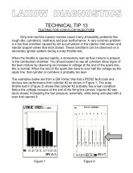
3. Exhaust <strong>Gas</strong> Relationships:<br />
Become familiar with the High/Low combination of exhaust gases and the likely problems they<br />
point to. See Figure 1 below.<br />
Figure 1: Exhaust <strong>Gas</strong> Relationship Chart<br />
Potential Problems Hydrocarbons<br />
Carbon<br />
Monoxide Oxygen<br />
Carbon<br />
Dioxide<br />
HC (PPM) CO (%) O2 (%) CO2 (%)<br />
Normal combustion efficiency Low Low Low High<br />
Engine Mechanical Issues High Low High Low<br />
Cooling System Issue-Cold Engine High High Low Low<br />
Ignition misfire, false air, lean condition High Low High Low<br />
Rich mixture Slightly High High Low Low<br />
Rich mixture with ignition misfire condition High High High Low<br />
Exhaust leak and air injection issues Low Low High Low<br />
Lean mixture High Low High Low<br />
Courtesy of PWR Training.<br />
Catch a Wave!