hand-held tester strategies - Automotive Electronics Services
hand-held tester strategies - Automotive Electronics Services
hand-held tester strategies - Automotive Electronics Services

You also want an ePaper? Increase the reach of your titles
YUMPU automatically turns print PDFs into web optimized ePapers that Google loves.
HAND-HELDTESTERSTRATEGIESThere are some marvelous <strong>hand</strong>-<strong>held</strong> <strong>tester</strong>s out there. Deciding which oneto use depends on the type of test you have to perform, the type of informationyou seek and which particular meter works best in a given situation.One of the keys to success in thisbusiness is being able to identify whatwe know and what we need to know.One discipline often overlooked is theunderstanding of the tools we use fordiagnosis. The chart in Fig. 1 on page24 shows the relationship these toolshave to the other disciplines of automotiverepair. Basically, it says that technologyis the foundation of an automotivesystem, the strategy operates thesystem and the tools allow us to see intothis technology and strategy. Our abilityto perform a professional diagnosis dependson our understanding of theseelements individually and as a whole.The ideal starting place is to focuson the strategy. But if we don’t considerthe other elements, we eventuallystall because our strength is limited byour weakness. For example, if we failBY JORGE MENCHUBottle rocket to Space Shuttle, test light to DSO. In technology,things never do stay the same. The automobile and thetools we use are certainly no exceptions. While this mightseem like a drawback at first, in fact, it’s a blessing, because it opensthe door of opportunity for the motivated and technically minded.to understand what our test equipmentoffers, then how can we validate or relyon the data it gathers?This article will look at an evolutionin electronic test equipment, startingwith the basic test light and endingwith the latest in lab scope technology.This evolution is based on the featuresthe equipment offers as opposedto when the equipment was introduced.The goal is to point out thecharacteristics we need to be aware ofwhen we gather data.The Test LightWhen I started as a technician, one ofmy first diagnostic tools was a simpletest light. A test light is just what thename implies—a light that tests for currentflow. One characteristic that governsthe use of a test light is the formatin which it offers information—thelight is either bright, dim or off. Anothercharacteristic, often referred to asthe loading effect, is its low input impedance.The term impedance as definedin an electronics dictionary is “thetotal opposition offered by a circuit ordevice to the flow of alternating current.”For our purposes, we can substitutethe word resistance for impedance,resulting in a definition of “the oppositionto the flow of current.” Most testlights have low resistance, meaningthey allow what could be considered alot of current to flow, especially in thecase of delicate electronic circuits.The word delicate refers to a circuit’sability to supply current to a load(such as a test light) without affectingits voltage. What would you expect tohappen if we connected a test light to22 January 1998
Illustrations: Jorge MenchuJanuary 199823
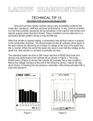
Hand-Held Tester StrategiesFig. 1 Fig. 2an oxygen sensor? The O 2 sensor circuitworks with low voltages and certainlysmall amounts of current, right?Because it can’t supply enough currentto turn on the light, it instead actsas a path to ground, resulting in ashorting of the circuit (Fig. 2).Because of this low-impedancecharacteristic, test light usage shouldbe limited to those circuits that drawlots of current, such as headlight andtaillight circuits, system power andground circuits, etc.The Digital MultimeterThe next step up the test equipmentevolutionary ladder is the digital multimeter(DMM). Most DMMs arehigh-impedance devices that have a10-megohm rating. Using a high-impedancemeter allows us to connectto delicate circuits without “loading”the circuit, which can result in an unwantedchange in the signal.The multiple measurement featuresof a DMM also take us to thenext level in information gathering.We can now read the pulse width ofan injector or the duty cycle of afeedback carb solenoid, things a commontest light can’t do.Another strength of the DMM is theformat of the display, which is easy toread and understand. But it’s importantthat it not update too fast. If it did, thenumbers would become an unreadableblur. Most DMM screens, therefore,update one to four times per second.This can be somewhat limiting, especiallywhen you’re trying to measurefaster signals. Some DMMs have analogbar graphs to help overcome thelimitations of a slow screen update.Another interesting fact of DMMs isthe way the meter arrives at the valuethat’s displayed; it averages the signal.In the case of the Fluke 88, for example,the signal is continuously measuredup to 40 times per second. The display,on the other <strong>hand</strong>, updates from one tofour times per second, depending onthe type of measurement. The valueused for the display, therefore, is an averagedvalue, as opposed to one froman individual measurement.In many test situations, this is not aconcern, but when considering highspeedcircuits and intermittent glitches,it can be. For example, Fig. 3 shows aFig. 3screen capture from a Fluke 97 inDMM mode. The signal it’s reading isthe digital output from a Snap-on signalgenerator board. The output was set to147 Hz with the intermittent glitch featureturned on, which causes two consecutivecycles to drop out every twoseconds. In this case (DMM mode), noticehow the meter was not capable ofdetecting the glitch. Considering thatfewer than a third of the cycles are beinganalyzed, this is not surprising. Andeven if the problem were measured itwould probably be lost in the averaging.To counteract this, some DMMs offera Min/Max feature. Min/Maxrecording is a very powerful featurethat stores the highest and lowestmeasured values in memory. Thereare many situations where Min/Max isideal, such as when you wish to determinethe operational range of a signalor when testing a steady signal such asa power or ground where you suspecta glitch. Unfortunately for many meters,the values stored in the Min/Maxmemory buffers are based on the averagedvalue used for the regular display.An exception is the Fluke 87,which offers a 1mS Peak Hold feature.Another characteristic is what I callthe Min/Max window, which is definedby the actual Min/Max values. Anychange that takes place in a signal thatfalls in between these values is ignoredby the Min/Max. For example, if you’rereading the frequency of a crank positionsensor from idle to cruise, the Min24 January 1998
will reflect the frequency atidle and the Max the frequencyat highest rpm the enginereached. If a glitch occurs atcruise speed and is measuredat a value higher than thatrecorded at idle and lowerthan that recorded at thehighest speed of the engine, itwill be ignored.The GraphingMultimeterThe next step up in the evolutionof <strong>hand</strong>-<strong>held</strong> test gear isthe graphing multimeter(GMM). The graphing meteroperates on the same principlesas a DMM and has theFig. 4same limitations; about the only differencelies in the display. The GMM displaycharts out the measured values ona two-dimensional graph, where thechanges from left to right representtime and the changes top to bottom theactual measurement values. The chartoffers the history and trends of a signal.Fig. 4 is a screen capture from theFluke 98 Series II in the Plot Readings(GMM) mode. While this screen offersmuch information by displaying multipleparameters of an input signal, it’snot really adept at capturing that fast orseldom-occurring glitch.The Power Graphing MeterThe power graphing meter (PGM) isnext up the evolutionary ladder. Thefirst PGM offered for automotive applicationswas the Snap-on Vantage,with other meters now also offeringPGM features. The PGM is a muchneededbridge between the DSO andDMM.The power graphing meter overcomesthe limitations of the digitalmultimeter and the graphing multimeter.To display information, it usesa chart similar to a GMM. What setsit apart is the way it arrives at the valuesused for display, which are not“averaged.” Here’s how it works:First, the PGM measures a signalvery rapidly. (In the case of the Vantage,it analyzes every cycle of arepetitive signal up to 20 kHz.) Themeasured values are then stored intomemory, representing the minimum,maximum, average and now (current)values. When it’s time to plot the nextvalue to the chart on the display(don’t mix this up withscreen refresh), the mostsignificant is selected fromthe min, max, and nowmemory registers. At thispoint, the registers are resetand the process is repeated.Since the Min/Max is resetevery time a plot is made,this minimizes the Min/Maxwindow effect. The result isa meter that is extremely accuratefor glitch detectionon repetitive signals.The screen in Fig. 5 wascaptured with the Snap-onVantage hooked up to a signalgenerator board withthe glitch feature enabled,as in the previous example. Noticehow the Vantage captures the signaldropout every time!So have we found the ultimate diagnostictool? We’re getting closer,but there are still characteristics weneed to be aware of. For example,when testing repetitive signals, thereis what I call a reaction window—theminimum values a signal has to maintainto be measured. This holds truefor all meters discussed so far. Whenthese meters are used to measure frequency,duty cycle, pulse width, etc.,they actually react to the signal in asimilar way the PCM reacts to thecrankshaft position sensor.Figs. 6 and 7 are two examples fromthe Fluke 97 set in DMM mode. Inthis mode, the meter also displays awaveform. The expected signal shouldFig. 5 Fig. 6 Fig. 7January 199825
Hand-Held Tester Strategieshave a peak voltage of 5 volts,as shown on the left. At right,a load was added to the signal,bringing the peak voltagedown to 2.4 volts. Note thatthe frequency is basically thesame! It was not until thevoltage reading went below2.4 volts that the frequencyreading became unreliable.So in this case, the reactionwindow is from 2.4 to 5 volts.Be forewarned, the reactionwindow (or trigger point) thesignal has to reach can varyamong test instruments, andeven test functions.At this point we still don’thave an instrument capableof showing a true picture of Fig. 8the signal—there’s still someuncertainty as to whether the signal isworking as the design engineer intended.We could try to develop apicture by reading multiple parametersof the signal such as voltage, dutycycle and frequency, or we can simplygo to the next step.The Digital StorageOscilloscopeThe digital storage oscilloscope’smain role is to take a picture of theelectrical voltage in a circuit, resultingin a two-dimensional graph calleda waveform. As with the GMM andPGM, the DSO’s horizontal axis representstime, but in this case, the verticalalways represents voltage levels.The DSO is a voltmeter and performsvoltage measurements similarto the other meters mentioned so far.The difference is the amount of controlthe user has over the acquisitionof the waveform and the speed atwhich the DSO can sample the signal.For example, the user has controlover the voltage and time resolutionof the display and the trigger settingsused to initiate the waveform captureand display. This type of control is extremelyhelpful when there’s a needto analyze complex signals or to viewinto extreme detail. Some scopes offerup to four channels, which makesthem indispensable for analyzing therelationships of many signals.Fig. 9Fig. 8 is a good example of the detaila waveform offers. This signal isfrom the Snap-on signal generatorboard that was used to capture thescreens in Figs. 3 and 5. In this case,we can actually see the dropout of thesignal that the DMM, GMM or PGMcould only indicate, at best. It’s interestingto note that if this were an actualrepair, the DMM, GMM andPGM would offer only enough informationto determine that there is aproblem, and any repairs based onthat information without further testingwould be based on experience.From Figs. 3 and 5 there isno way to tell if the signaldropped high or low or didsomething else. With a waveform,we can see it and takeour analysis to the next step.For example, if this were atypical three-wire Hall sensorand the signal went high insteadof low, I would know,based on the way Hall sensorcircuits are configured, thatthe circuit was good from mytest point all the way to thepull-up resistor inside thePCM. Since this was not thecase and the dropout did golow, the circuit from my testpoint to the PCM, includingthe pull-up resistor, is suspect andadded to the “possibilities” list.This all sounds very powerful andit is, but again, there are drawbacks.To take advantage of the true powerof a lab scope, you have to learn howto control it and have a decent understandingof electricity. I’m not lookingto scare anyone away from DSOs, because,fact is, you don’t have to be anexpert to use one. Many DSOs offerautomated setups to get you startedand waveform libraries to give you astarting point or at least let you work26 January 1998
Fig. 10 Fig. 11in a “go/no-go” mode. But regardlessof your ability, there are aspects thatyou need to be aware of.I’ve already stated that the DSOoffers a voltage picture of electricalsignals. The major concerns are howoften the picture is taken and displayed(screen update), and in whatdetail each picture is presented.Most DSOs update the display twoto seven times per second. Thismeans that any event that takes placebetween the updates is completelymissed! In Fig. 8, there are about 14cycles of the signal on display (includingthe two dropped cycles). Multiplythis by a screen update of four timesper second and the scope is displaying56 cycles every second. Problemis, this signal is occurring at 147 cyclesa second. So at this rate, theDSO is displaying fewer than half ofthe cycles that occur, opening thedoor for your missing important data.The next concern is the detail ofeach picture. Most DSOs use anLCD display. These are similar to agrid of lights, called pixels. To fill thedisplay, the DSO will have to samplea signal at least once for every columnof pixels. Now what would youexpect to happen when a signal eventsuch as a spike occurs in between thesamples? Right, it will be completelymissed! Fig. 9 shows a good secondaryignition pattern that’s missingthe inductive kick. We know it mustbe there because the rest of the signalis good. In this case, the spike occurred—thescope simply missed it.Many DSOs offer special featuresto overcome these limitations. In thecase of the missed spike, some scopeshave a Min/Max feature, sometimesreferred to as glitch detect. Withglitch detect, the highest and lowestsignal values are stored in memory.When it’s time to plot to the display,the DSO uses these Min/Max values.Then every time a new plot is made,the Min/Max is reset and the processrepeats itself. Instead of sampling thesignal once for every column of pixels,the DSO samples it at a very highrate—in the case of the Fluke 97, forexample, 25 million times per second.To overcome the slow screen updaterate, some DSOs offer the abilityto continuously record the signal inmemory for playback. In the case ofthe Fluke 98, 128 screens worth ofdata can be recorded in memory inwhich no data is missed. But this featureis good only with a time base settingof 20mS or slower.The Power Graphing ScopeThe next logical step in the evolution of<strong>hand</strong>-<strong>held</strong> test equipment—and thelatest addition to our tool arsenal—isthe power graphing scope (PGS). OTCand Mac Tools have both introduced anew meter (called Perception by OTCand ET2025 by Mac) that promises tocombine the benefits of both the PGMand DSO by using the analysis powerof the PGM to determine when to takea picture of the signal. In other words,the signal is constantly analyzed forchanges that could signify a glitch.When this occurs, it triggers the meterinto taking a picture of the signal at thatvery moment for immediate analysis.In a NutshellFortunately, most automotive problemsare repetitive enough that mostmeters will easily capture a problem.But this report isn’t about those situations;it’s about seldom-occurringglitches and the tools needed to nailthem. Considering this, then, there isno question about the value of thedigital storage oscilloscope and powergraphing meter.What many techs have found isthat tools like the PGM are going tobe ideal for finding circuits whosesignals indicate that a problem occurred.The lab scope will be usedwhen there’s a need to truly analyzethat signal, and to prove it’s workingas the engineers intended. Figs. 10and 11 clearly show this difference.In Fig. 10, we see a PGM chart of atiming control pulse as the engine isrevved. It looks fine and the engine isrunning smoothly, but it doesn’t offermuch detail about the actual activityof the circuit. Fig. 11 is the same signalcaptured using a DSO. Noticethat the signal does not reach ground!A developing problem? Perhaps.I hope this article makes you awareof the importance of understandingthe equipment you use. Since technologyis not going to slow down, wecan’t, either! I encourage you to lookon the increasing complexity we’refaced with as a challenge that motivatesyou. After all, motivation doesopen the door to opportunity.For a free copy of thisarticle, write to: Fulfillment Dept.,MOTOR Magazine, 5600 CrooksRd., Troy, MI 48098. Additionalcopies are $2 each. Send checkor money order.January 199827