

Schweiger_ NUMGE_2002.pdf - Plaxis
Schweiger_ NUMGE_2002.pdf - Plaxis
Schweiger_ NUMGE_2002.pdf - Plaxis

Create successful ePaper yourself
Turn your PDF publications into a flip-book with our unique Google optimized e-Paper software.
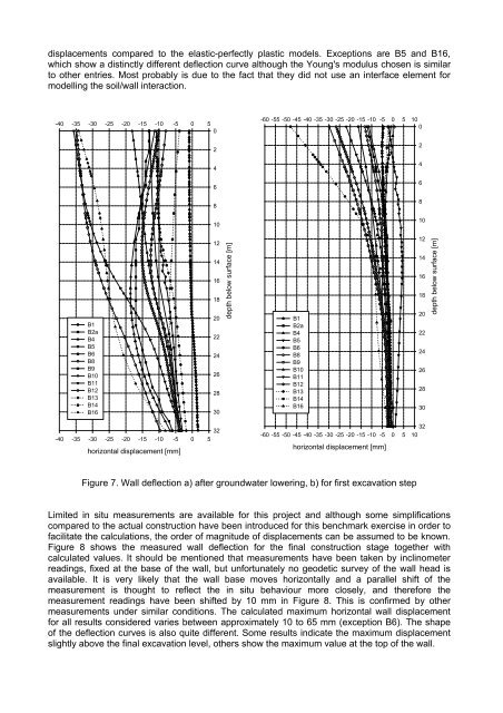
displacements compared to the elastic-perfectly plastic models. Exceptions are B5 and B16,<br />
which show a distinctly different deflection curve although the Young's modulus chosen is similar<br />
to other entries. Most probably is due to the fact that they did not use an interface element for<br />
modelling the soil/wall interaction.<br />
-40 -35 -30 -25 -20 -15 -10 -5 0 5<br />
0<br />
2<br />
4<br />
6<br />
8<br />
10<br />
-60 -55 -50 -45 -40 -35 -30 -25 -20 -15 -10 -5 0 5 10<br />
0<br />
2<br />
4<br />
6<br />
8<br />
10<br />
B1<br />
B2a<br />
B4<br />
B5<br />
B6<br />
B8<br />
B9<br />
B10<br />
B11<br />
B12<br />
B13<br />
B14<br />
B16<br />
12<br />
14<br />
16<br />
18<br />
20<br />
22<br />
24<br />
26<br />
28<br />
30<br />
depth below surface [m]<br />
B1<br />
B2a<br />
B4<br />
B5<br />
B6<br />
B8<br />
B9<br />
B10<br />
B11<br />
B12<br />
B13<br />
B14<br />
B16<br />
12<br />
14<br />
16<br />
18<br />
20<br />
22<br />
24<br />
26<br />
28<br />
30<br />
depth below surface [m]<br />
32<br />
-40 -35 -30 -25 -20 -15 -10 -5 0 5<br />
horizontal displacement [mm]<br />
32<br />
-60 -55 -50 -45 -40 -35 -30 -25 -20 -15 -10 -5 0 5 10<br />
horizontal displacement [mm]<br />
Figure 7. Wall deflection a) after groundwater lowering, b) for first excavation step<br />
Limited in situ measurements are available for this project and although some simplifications<br />
compared to the actual construction have been introduced for this benchmark exercise in order to<br />
facilitate the calculations, the order of magnitude of displacements can be assumed to be known.<br />
Figure 8 shows the measured wall deflection for the final construction stage together with<br />
calculated values. It should be mentioned that measurements have been taken by inclinometer<br />
readings, fixed at the base of the wall, but unfortunately no geodetic survey of the wall head is<br />
available. It is very likely that the wall base moves horizontally and a parallel shift of the<br />
measurement is thought to reflect the in situ behaviour more closely, and therefore the<br />
measurement readings have been shifted by 10 mm in Figure 8. This is confirmed by other<br />
measurements under similar conditions. The calculated maximum horizontal wall displacement<br />
for all results considered varies between approximately 10 to 65 mm (exception B6). The shape<br />
of the deflection curves is also quite different. Some results indicate the maximum displacement<br />
slightly above the final excavation level, others show the maximum value at the top of the wall.


