User manual Arc Dot Power - Anolis
User manual Arc Dot Power - Anolis
User manual Arc Dot Power - Anolis

You also want an ePaper? Increase the reach of your titles
YUMPU automatically turns print PDFs into web optimized ePapers that Google loves.
Version 1.1
<strong>Arc</strong><strong>Dot</strong> <strong>Power</strong><br />
Table of contents<br />
1. Important safety instructions........................................................................................ 3<br />
1. Consignes de sécurité importantes.............................................................................. 4<br />
2. Operating determinations.............................................................................................. 4<br />
3.Description of the <strong>Arc</strong><strong>Dot</strong> <strong>Power</strong>.................................................................................... 5<br />
4.Installation........................................................................................................................ 5<br />
4.1.Connection to the mains:............................................................................................ 5<br />
4.2.Mounting the <strong>Arc</strong><strong>Dot</strong> <strong>Power</strong>........................................................................................ 6<br />
4.3. Connecting <strong>Arc</strong><strong>Dot</strong><strong>Power</strong> and <strong>Arc</strong><strong>Dot</strong>s...................................................................... 6<br />
5.<strong>Arc</strong><strong>Dot</strong> <strong>Power</strong> - Control menu map................................................................................ 8<br />
6.<strong>Arc</strong><strong>Dot</strong> <strong>Power</strong> - DMX protocol,........................................................................................ 9<br />
7.Control board................................................................................................................. 10<br />
7.1 Addressing the <strong>Arc</strong><strong>Dot</strong> <strong>Power</strong> .................................................................................. 10<br />
7.2 <strong>Arc</strong><strong>Dot</strong>s .................................................................................................................... 10<br />
7.3 Personality................................................................................................................ 11<br />
7.4 Fixture information.................................................................................................... 11<br />
7.5 Test........................................................................................................................... 12<br />
7.6 Special functions....................................................................................................... 12<br />
8.Technical Specifications:.............................................................................................. 14<br />
9. Replacing the fuse ....................................................................................................... 15
CAUTION!<br />
Unplug mains lead before opening the housing!<br />
FOR YOUR OWN SAFETY, PLEASE READ THIS USER MANUAL CAREFULLY<br />
BEFORE YOU INITIAL START - UP!<br />
ATTENTION!<br />
Débrancher l’appareil avant d'ouvrir le boîtier!<br />
POUR VOTRE SÉCURITÉ, LISEZ ATTENTIVEMENT CETTE NOTICE AVANT LA PRE-<br />
MIERE UTILISATION<br />
1. Important safety instructions<br />
Every person involved with installation and maintenance of this product has to:<br />
- be qualilfied<br />
- follow the instructions and heed all warnings in this <strong>manual</strong><br />
CAUTION!<br />
Be careful with your operations. With a high voltage you can suffer<br />
a dangerous electric shock when touching the wires inside the unit!<br />
This product has left our premises in absolutely perfect condition. In order to maintain this condition and to<br />
ensure a safe operation, it is absolutely necessary for the user to follow the safety instructions and warning<br />
notes written in this <strong>manual</strong>.<br />
WARNING<br />
To prevent injury, this apparatus must be securely installed in accordance with the<br />
installation instructions.”<br />
Do not block any ventilation openings. Install in accordance with the manufacturer’s instructions.<br />
Do not install near any heat sources such as radiators, heat registers, stoves, or other apparatus (including<br />
amplifiers) that produce heat.<br />
Do not use this apparatus near water. Clean only with dry cloth.<br />
MAINS plug or an appliance coupler is used as the disconnect device, the disconnect device shall remain<br />
readily operable.<br />
Only use attachments/accessories specified by the manufacturer.<br />
Protect the power cord from being walked on or pinched particularly at plugs, convenience receptacles, and<br />
the point where they exit from the apparatus.<br />
Refer all servicing to qualified service personnel. Servicing is required when the apparatus has been damaged<br />
in any way, such as power-supply cord or plug is damaged, liquid has been spilled or objects have fallen into<br />
the apparatus, the apparatus has been exposed to rain or moisture, does not operate normally, or has been<br />
dropped.<br />
Use a source of AC power that complies with local building and electrical rules.AC power has to have both<br />
overload and short circuit protection.<br />
This device falls under protection class I.Therefore the <strong>Arc</strong><strong>Dot</strong><strong>Power</strong> has to be connected<br />
to a mains socket outlet with a protective earthing connection!
1. Consignes de sécurité importantes<br />
Toute personne impliquée dans l'installation et la maintenance de ce produit doit:<br />
- Être suffisamment qualifié<br />
- Suivre les instructions de ce manuel<br />
ATTENTION!<br />
Soyez prudent avec vos manipulations. Avec une haute tension, vous risquez un<br />
choc électrique en touchant les fils à l'intérieur de l'appareil!<br />
Ce produit a quitté nos ateliers dans un état irréprochable. Afin de maintenir cet état et pour assurer un bon<br />
fonctionnement, il est absolument nécessaire de suivre les consignes de sécurité et les notes contenues dans<br />
ce manuel.<br />
AVERTISSEMENT<br />
Pour éviter toute blessure, cet appareil doit être solidement fixé à en conformité<br />
avec les instructions d'installation. "<br />
Ne pas bloquer les ouvertures de ventilation. Installer conformément aux instructions du fabricant.<br />
Ne pas installer près de sources de chaleur telles que radiateurs, ou autres appareils (y compris les amplificateurs)<br />
produisant de la chaleur.<br />
Ne pas utiliser cet appareil près de l'eau. Nettoyer avec un chiffon sec.<br />
Une prise de branchement ou un coupleur est utilisé comme dispositif de déconnexion, ce dispositif doit rester<br />
facilement accessible.<br />
N'utilisez que des accessoires spécifiés par le fabricant.<br />
Protégez le cordon d'alimentation du piétinement ou pincement, particulièrement au niveau des fiches, des<br />
prises, et le point où ils sortent de l'appareil<br />
Confiez toute réparation à un personnel qualifié. Une réparation est nécessaire lorsque l'appareil a été endommagé<br />
de quelque façon que ce soit. cordon d'alimentation, fiche est endommagé, liquide renversé a l interieur,<br />
ou des objets sont tombés dans l'appareil, l'appareil a été exposé à la pluie ou à l'humidité, ne fonctionne pas<br />
normalement , ou s'il est tombé.<br />
Utilisez une source de courant alternatif qui est conforme a l’endroit ou vous vous trouvez. La source alternative<br />
doit avoir à la fois une protection de surcharge et de court-circuit.<br />
Ce dispositif relève de la classe de protection I. Par conséquent, la <strong>Arc</strong><strong>Dot</strong><strong>Power</strong><br />
doit être connecté à une prise électrique reliée à la terre!<br />
2. Operating determinations<br />
This product was designed for indoor use only.<br />
If the unit has been exposed to drastic temperature fluctuation (e.g. after transportation), do not switch it on<br />
immediately. The arising condensation water might damage your unit. Leave the unit switched off until it has<br />
reached room temperature.<br />
Avoid brute force when installing or operating the unit.<br />
When choosing the installation-spot, please make sure that the unit is not exposed to extreme heat, moisture<br />
or dust.<br />
Only operate the unit after having checked that the housing is firmly closed and all screws are tightly fastened.
The maximum ambient temperature 40° C must never be exceeded.<br />
Operate the unit only after having familiarized with its functions. Do not permit operation by persons not qualified<br />
for operating the unit. Most damages are the result of unprofessional operation!<br />
Please use the original packaging if the product is to be transported.<br />
Please consider that unauthorized modifications on the unit are forbidden due to safety reasons!<br />
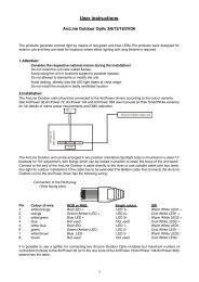
3.Description of the <strong>Arc</strong><strong>Dot</strong> <strong>Power</strong><br />
1 - Control board<br />
2 - <strong>Power</strong> cord<br />
3 - Ethernet<br />
4 - DMX Output<br />
5 - DMX Input<br />
6 - <strong>Arc</strong><strong>Dot</strong> output 4<br />
7 - <strong>Arc</strong><strong>Dot</strong> output 3<br />
8 - <strong>Arc</strong><strong>Dot</strong> output 2<br />
9 - <strong>Arc</strong><strong>Dot</strong> output 1<br />
4.Installation<br />
CAUTION!<br />
These servicing instructions are for use by qualified service personnel only. To<br />
reduce the risk of electric shock do not perform any servicing other than that contained<br />
in the operating instructions unless you are qualified to do so.<br />
4.1.Connection to the mains:<br />
The <strong>Arc</strong><strong>Dot</strong> <strong>Power</strong> is equipped with auto-switching power supply that automatically adjusts to any 50/60Hz AC<br />
power source from 100-240 Volts.<br />
The fixture is equipped the cord & plug QP 02 but you can use the following plugs: P620,24W47,14W49,24W<br />
49,26W81,HBL4720C,HBL2311, HBL2321,HBL2811 and the cords SJT or 22326.<br />
Cord plug connection:<br />
Cable (EU) Cable (US) Pin International<br />
Brown Black Live L<br />
Liht blue White Neutral N<br />
Yellow/Green Green Earth<br />
This device falls under protection class I.Therefore the <strong>Arc</strong><strong>Dot</strong> <strong>Power</strong> has to be connected<br />
to a mains socket outlet with a protective earthing connection.
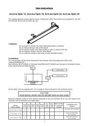
4.2.Mounting the <strong>Arc</strong><strong>Dot</strong> <strong>Power</strong><br />
The <strong>Arc</strong><strong>Dot</strong> <strong>Power</strong> should be be placed on a non-flammable flat surface in any orientation and fixed by the four<br />
screws.There are four mounting holes of a diameter of 5 mm in housing of the driver. Ensure that instalation<br />
place is enough ventilated.<br />
Screws<br />
Flat surface<br />
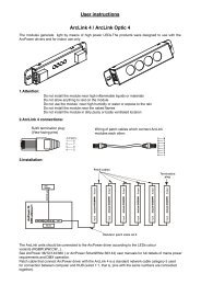
4.3. Connecting <strong>Arc</strong><strong>Dot</strong><strong>Power</strong> and <strong>Arc</strong><strong>Dot</strong>s<br />
Mounting holes<br />
Connect <strong>Arc</strong><strong>Dot</strong>s to the LED outputs of the <strong>Arc</strong><strong>Dot</strong><strong>Power</strong>, typically 25 <strong>Arc</strong><strong>Dot</strong>s per output (max. 35 <strong>Arc</strong><strong>Dot</strong>s).<br />
Max. number of all LED modules connected to the <strong>Arc</strong><strong>Dot</strong><strong>Power</strong> is 100. The <strong>Arc</strong><strong>Dot</strong>s can be interconnected<br />
directly or by using T- connectors - see the picture below. If you use Artnet for control of the <strong>Arc</strong><strong>Dot</strong> <strong>Power</strong>,<br />
you can connect <strong>Arc</strong><strong>Dot</strong>s to all LED outputs 1-4.<br />
For larger installation (more than 25 <strong>Arc</strong><strong>Dot</strong>s), the <strong>Arc</strong><strong>Dot</strong><strong>Power</strong> should be connected to the Robe Media Server<br />
which allows automatic pixel mapping and full control of the <strong>Arc</strong><strong>Dot</strong>s modules. Without Robe Media Server, you<br />
have to perform pixel mapping <strong>manual</strong>ly using the menu "dotS".<br />
To connect <strong>Arc</strong><strong>Dot</strong>s<br />
1. Disconnect <strong>Arc</strong><strong>Dot</strong><strong>Power</strong> from mains.<br />
2. Connect <strong>Arc</strong><strong>Dot</strong>s to the <strong>Arc</strong><strong>Dot</strong><strong>Power</strong>. Connect active terminators to each <strong>Arc</strong><strong>Dot</strong>s line.<br />
3. Connect <strong>Arc</strong><strong>Dot</strong><strong>Power</strong> to mains<br />
4. Run procedures Pixels checking (Find) and Pixel sorting (Sort) from menu <strong>Arc</strong><strong>Dot</strong> (dotS)<br />
5. Save found values with option Store (Stor)<br />
6. Disconnect the <strong>Arc</strong><strong>Dot</strong><strong>Power</strong> from mains and replace active terminators by passive terminators*.<br />
7. Connect the <strong>Arc</strong><strong>Dot</strong><strong>Power</strong> to mains and to the Robe Media Server.<br />
* Active terminators can remain permanent connected if there is place for them (they are biggers than passive<br />
ones).<br />
The minimum cable length of 0.3m<br />
between two T-connectors has to<br />
be kept in case that the pixel sorting<br />
is executed <strong>manual</strong>ly from the<br />
<strong>Arc</strong><strong>Dot</strong><strong>Power</strong> menu.<br />
<br />
This rule does not need to be kept<br />
if the Robe Media Server is used<br />
for pixel sorting<br />
Max. total length of cable depends<br />
on the number of <strong>Arc</strong><strong>Dot</strong>s connected<br />
to the <strong>Arc</strong><strong>Dot</strong><strong>Power</strong> (100 m<br />
@ 25 <strong>Arc</strong><strong>Dot</strong>s, 65 m @ 35 <strong>Arc</strong><strong>Dot</strong>s<br />
per output.<br />
Every <strong>Arc</strong><strong>Dot</strong> line has to<br />
be terminated with the<br />
passive terminator!
If the line between <strong>Arc</strong><strong>Dot</strong>s is disconected, the <strong>Arc</strong><strong>Dot</strong>s behind point of interrupt will not work. Before restoring<br />
connection betwen <strong>Arc</strong><strong>Dot</strong>s, switch off the <strong>Arc</strong><strong>Dot</strong><strong>Power</strong>.<br />
In case that some <strong>Arc</strong><strong>Dot</strong> is changed, the same address as had original <strong>Arc</strong><strong>Dot</strong> is assigned to it by <strong>Arc</strong><strong>Dot</strong>-<br />
<strong>Power</strong>. It is very important to save <strong>Arc</strong><strong>Dot</strong>s configuration at every change of the <strong>Arc</strong><strong>Dot</strong>.(Menu "<strong>Dot</strong>s"<br />
-> "Store"),<br />
Max. cable length between <strong>Arc</strong><strong>Dot</strong><strong>Power</strong> and the last connected <strong>Arc</strong><strong>Dot</strong> module should not be exceeded:<br />
100m @ 25 <strong>Arc</strong><strong>Dot</strong>s per LED output or 65 m @ 35 <strong>Arc</strong><strong>Dot</strong>s per LED output. Only one <strong>Arc</strong><strong>Dot</strong> module can<br />
be connected to the T-connector.<br />
Note: If DMX is used for control of the <strong>Arc</strong><strong>Dot</strong> <strong>Power</strong>, the LED outputs 1-3 may be used only (LED output<br />
load is the same as in case of control by Artnet - typically 25 LED modules, max 35 LED modules and 100<br />
modules max. load of <strong>Arc</strong><strong>Dot</strong><strong>Power</strong>).<br />
Every <strong>Arc</strong><strong>Dot</strong> line has to be terminated with the passive terminator!<br />
The Robe Media Server allows to choose two modes of <strong>Arc</strong><strong>Dot</strong>s connection: Fixed-wiring mode and Picture<br />
mode. For detailed description see the user <strong>manual</strong> of the Robin Media Server.
5.<strong>Arc</strong><strong>Dot</strong> <strong>Power</strong> - Control menu map<br />
Default settings=Bold print<br />
A001<br />
dM. Ad.<br />
IP.Ad<br />
dEF.A<br />
SEt<br />
CUS.A.<br />
IP.A1 (0-255)<br />
:<br />
IP.A4 (0-255)<br />
SEt<br />
nEt M.<br />
nE.M.1 (0-255)<br />
:<br />
nE.M.4 (0-255)<br />
dotS<br />
PErS<br />
InFo<br />
FInd<br />
Sort<br />
F.tin (0-255)<br />
CurV (0-255)<br />
Stor.<br />
Art.U. (0-255)<br />
dISP.<br />
turn<br />
d.On<br />
d.Int (30, 50, 80,100)<br />
dM.In.<br />
DMH<br />
Eth<br />
dEF.S.<br />
S.VEr.<br />
IP.Ad.<br />
d.1<br />
:<br />
MA.In<br />
IP.A1<br />
:<br />
IP.A4<br />
rdM.U.<br />
rdM.1<br />
:<br />
rdM.3<br />
MAC.A<br />
MAC.1<br />
:<br />
MAC.3<br />
dotS<br />
d.MiS<br />
nEU.d.<br />
SPEC<br />
UPd<br />
(no, YES)
6.<strong>Arc</strong><strong>Dot</strong> <strong>Power</strong> - DMX protocol,<br />
version 1.0<br />
Channel Value Function Type of control<br />
1<br />
2<br />
3<br />
4<br />
5<br />
6<br />
7<br />
8<br />
9<br />
298<br />
299<br />
300<br />
0-255<br />
0-255<br />
0-255<br />
0-255<br />
0-255<br />
0-255<br />
0-255<br />
0-255<br />
0-255<br />
0-255<br />
0-255<br />
0-255<br />
<strong>Arc</strong><strong>Dot</strong> 1<br />
Red<br />
Red LED saturation control (0-100%)<br />
Green<br />
Green LED saturation control (0-100%)<br />
Blue<br />
Blue LED saturation control (0-100%)<br />
<strong>Arc</strong><strong>Dot</strong> 2<br />
Red<br />
Red LED saturation control (0-100%)<br />
Green<br />
Green LED saturation control (0-100%)<br />
Blue<br />
Blue LED saturation control (0-100%)<br />
<strong>Arc</strong><strong>Dot</strong> 3<br />
Red<br />
Red LED saturation control (0-100%)<br />
Green<br />
Green LED saturation control (0-100%)<br />
Blue<br />
Blue LED saturation control (0-100%)<br />
:<br />
:<br />
:<br />
:<br />
:<br />
:<br />
:<br />
<strong>Arc</strong><strong>Dot</strong> 100<br />
Red<br />
Red LED saturation control (0-100%)<br />
Green<br />
Green LED saturation control (0-100%)<br />
Blue<br />
Blue LED saturation control (0-100%)<br />
proportional<br />
proportional<br />
proportional<br />
proportional<br />
proportional<br />
proportional<br />
proportional<br />
proportional<br />
proportional<br />
proportional<br />
proportional<br />
proportional
7.Control board<br />
The control panel situated on the top cover of the <strong>Arc</strong><strong>Dot</strong> <strong>Power</strong> allows fixture addressing and set the driver´s<br />
behaviour.<br />
Control elements:<br />
[ENTER] button- enters menu,confirms adjusted values and leaves menu.<br />
, [UP] button and[DOWN] button- moves between menu items on the the same level, sets values.<br />
[ESCAPE] button- leaves the menu without saving value.<br />
7.1 Addressing the <strong>Arc</strong><strong>Dot</strong> <strong>Power</strong><br />
M.Ad. - DMX address. Select this menu item to set desired DMX address.l<br />
IP.Ad. - IP address. Select this menu item to set desired IP address. IP address is the Internet protocol<br />
address.The IP uniquely identifies any node (fixture) on a network. There cannot be 2 fixtures with<br />
the same IP address on the network!<br />
dEF.A. - Default IP address. This address is derived from fixture´s MAC address and<br />
cannot be changed. Confirm item "SEt" if you want to set default IP address.<br />
CUS.A. - Custom IP address. IP address consists of four decimal numbers, each ranging<br />
from 0 to 255, separated by dots, e.g., 172.16.254.1. Each part represents a group of 8 bits<br />
(octet) of the address.<br />
The following items "IP.A1", "IP.A2", "IP.A3", "IP.A4" allow to set each part (number) of<br />
the address. After setting desired IP address, confirm item "SEt" to save set address.<br />
nEt.M. - Net mask. Select this menu item to set desired Net mask. A Net mask is a 32-bit mask used to divide<br />
an IP address into subnets and specify the networks available hosts.<br />
The following items "nE.M.1", "nE.M.2", " nE.M.3", " nE.M.4" serve for seting of each part (number) of the<br />
net mask.<br />
7.2 <strong>Arc</strong><strong>Dot</strong>s<br />
Use this menu to prepare <strong>Arc</strong><strong>Dot</strong>s for operation in desired matrix.<br />
FInd - Pixels checking. This function checks all pixels connected to the fixture and<br />
the message “donE” is displayed after finishing the procedure.<br />
NOTE: Active terminator has to be connected to the last <strong>Arc</strong><strong>Dot</strong> of each <strong>Arc</strong><strong>Dot</strong>s line.<br />
Sort - Pixels sorting. This function starts auto-sorting of each conncted <strong>Arc</strong><strong>Dot</strong> modules. After sorting, dots<br />
will have order Red, Green, Blue.<br />
NOTE: Active terminator has to be connected to the last <strong>Arc</strong><strong>Dot</strong> of each <strong>Arc</strong><strong>Dot</strong>s line.<br />
M.F.ti. --- Max. fade time. Select this menu item to set a desired max. fade time (0-25.5 sec.). This adjusted<br />
fade time influences fade of RGB and dimmer during DMX operation:<br />
10
If time between two receiving DMX values is > than fade time set in the item M.F.ti., the entire adjusted fade<br />
time will be used.<br />
If time between two receiving DMX values is < than fade time set in the item M.F.ti., the adjusted fade time will<br />
be reduced to fill entire time between the two receiving DMX values.<br />
e.g. M.F.ti.=2sec. and fixture has received Red=0 DMX, after 5 seconds will receive Red=255 DMX. It means,<br />
that red will go to full intensity during 2 seconds.<br />
M.F.ti.=8 sec. and fixture has received Red=0 DMX, after 5 seconds will receive Red=255 DMX. It means,<br />
that red will go to full intensity during 5 seconds. (Max, fade time is reduced from 8 sec. to 5 sec.).<br />
CurV. --- Saturation curve. This menu item allows you to select desired running of colour saturation. You can<br />
select 255 colour saturation runnings in all. The value 0 corresponds linear curve, the value 128 corresponds<br />
exponential curve with index 1.9 and last value 255 corresponds exponential curve with index 2.6.<br />
Stor. --- Store. Select this function to save all adjustem items in the menu "dotS"<br />
7.3 Personality<br />
Use this menu to modify the <strong>Arc</strong><strong>Dot</strong><strong>Power</strong> operating behavior.<br />
Art.U. - ArtNet Universe. Select the menu item to set ArtNet universe. Art-Net is a proprietary protocol for<br />
transmitting DMX512 (with RDM) over UDP/IP. Up to sixteen DMX512 universes can be accessed through one<br />
IP subnet. The Universe is a single DMX 512 frame of 512 channels.<br />
dISP. - Display adjusting. This menu allows you to change the display settings.<br />
turn - Select this item to turn the display by 180°.<br />
d.On - This menu item allows you to keep the display on or to turn it off automatically 2 minutes<br />
after last pressing any button on the control panel.<br />
d.Int. - Select this menu item to adjust the display intensity (30, 50, 80, 100-max.).<br />
dM.In. - DMX input selection. This menu allows to choose desired DMX data input:<br />
dMH - DMX. If this input is selected, only LED outputs 1-3 are active.<br />
Eth - Ethernet. If this input is selected, all LED outputs (1-4) are active.<br />
dEF.S. - Default setting. Select this option to reset fixture personalities and setting to the default (factory).<br />
values.<br />
7.4 Fixture information<br />
Use this menu to read useful information about the fixture.<br />
S.VEr. - Software version. Select this menu item to read software versions.<br />
11
d.1-d.100 - <strong>Dot</strong> version. The items show software version of each <strong>Arc</strong><strong>Dot</strong>.<br />
MA. In - Driver version. The item shows software version of the <strong>Arc</strong><strong>Dot</strong>Pover.<br />
IP.Ad. - IP address . Select this menu item to read individul parts ( "IP.A1", "IP.A2", "IP.A3", "IP.A4") of the<br />
current IP address.<br />
rdM.U. - RDM Universe ID . Select this menu item to read individul parts ( "rdM.1", "rdM.2", "rdM.3") of the<br />
RDM Universe ID.<br />
MAC.A. - MAC Address. Select this menu item to read individul parts ( "MAC.1", "MAC.2", "MAC.3") of the<br />
MAC address.<br />
dotS. - <strong>Arc</strong><strong>Dot</strong>s information. Select this menu item to read information about <strong>Arc</strong><strong>Dot</strong>s<br />
d.MiS - Missing <strong>Arc</strong><strong>Dot</strong>. The item shows the number of <strong>Arc</strong><strong>Dot</strong>s which were not detected<br />
by the Pixel checking procedure ("Find") .<br />
nEU.d - New <strong>Arc</strong><strong>Dot</strong>. The item shows the number of recently connected <strong>Arc</strong><strong>Dot</strong>s.<br />
7.5 Test<br />
The menu starts program sequense over all connected <strong>Arc</strong><strong>Dot</strong>s in order red, green, blue. Before running this<br />
Test program, the "Pixel checking" and Pixel sorting" procedures from menu PErS have tu be performed.<br />
7.6 Special functions<br />
Use this menu for special services.<br />
uPd. --- Software update - Using this function you can update software in the fixture via PC and USB (serial<br />
link).<br />
The following are required in order to update software:<br />
- PC running Windows 95/98/2000/XP/7 or Linux<br />
- DMX Software Uploader<br />
- Flash cable RS232/DMX (No.13050624) or Robe Universal Interface<br />
-<br />
Note1. Software update should execute a qualified person.If you lack qualification, do not try the update<br />
yourself and ask for help your ANOLIS distributor.<br />
Note 2. IP address, and settings in menu " PErS" will be set to their default values.<br />
To update software in the fixture:<br />
1.Installation of DMX Software Uploader:<br />
1.DMX Software Uploader program is available from the ANOLIS web site at WWW.anolis.cz.<br />
2.Make a new directory ( e.g. ANOLIS_Uploader) on your hard disk and download the software to it.<br />
3.Unpack the program from the archives. Program file has name:DSU_name of corresponding<br />
fixture_SoftwareID.SoftwareID describes the versions of fixture software included in DMX Software<br />
Uploader. Higher number means later software versions.<br />
2.Fixture software updating:<br />
1.Determine which of your COM port is available on your PC and connect it with to the DMX input<br />
of the fixture using the Flash cable. Do not extend this cable! Disconnect the fixture from the<br />
other fixtures in DMX chain! Turn on the computer and the fixture.<br />
2.Switch the fixture to the update mode by selecting the option Software update in menu Special<br />
Functions on the fixture control panel:SPEC-->UPd-->yES.(From this option you cannot return<br />
back to the main menu. If you do not want to continue in software update, you have to switch off<br />
and on the fixture to leave this option!)<br />
3.It is recommended that you exit all programs before running the Software Uploader.<br />
4.Start the Software Uploader program. Select desired COM and then click Connect button.<br />
If the conection is OK, click Start Uploading button to start uploading. It will take several minutes to<br />
perform software update.All processors will be updated (including processors with the same<br />
software version).<br />
If you wish to update only later versions of processors, enable the Incremental Update check box.<br />
12
Avoid interrupting the process. Update status is being displayed in the list window.<br />
When the update is finished, the line with the text “The fixture is successfuly updated‘ will appear<br />
in this window and the fixture will reset with the new software.<br />
Note: In the case of interruption of the upload process (e.g. power cut), the fixture remains in the update mode<br />
and you have to repeat the software update again.<br />
13
8.Technical Specifications:<br />
<strong>Power</strong> supply<br />
Input Voltage: 100-240 V AC, 50-60 Hz<br />
Fuse:T 8 A<br />
Max.Pover Consumption: 640W<br />
Control and programming<br />
Protocols: USITT DMX-512, Artnet<br />
Display: 4 digit LED<br />
4 control buttons<br />
DMX channels<br />
<strong>Dot</strong> 1: 1=R1 <strong>Dot</strong> 2: 4=R2 ........................................................<strong>Dot</strong> 100: 298=R100<br />
2=G1 5=G2 ........................................................ 299=G100<br />
3=B1 6=B2 ........................................................ 300=B100<br />
Output<br />
Max.Output Voltage:48V DC<br />
Max.Output power: 583 W<br />
<strong>Arc</strong><strong>Dot</strong> outputs: 4<br />
Max.load per <strong>Arc</strong><strong>Dot</strong> output: 35 <strong>Arc</strong><strong>Dot</strong>s (typically 25 <strong>Arc</strong><strong>Dot</strong>s)<br />
Total max.load per <strong>Arc</strong><strong>Dot</strong> <strong>Power</strong>: 100 <strong>Arc</strong><strong>Dot</strong>s<br />
Maximum cable length between <strong>Arc</strong><strong>Dot</strong> output and the last connected <strong>Arc</strong><strong>Dot</strong> module<br />
100 m (25 <strong>Arc</strong><strong>Dot</strong>s per output)<br />
65 m (35 <strong>Arc</strong><strong>Dot</strong>s per output)<br />
Total heat dissipation<br />
max. 1980 BTU/hr<br />
Connections<br />
DMX 512: 3-pin male/female XLR<br />
Output<br />
1 Shield<br />
2 Signal (-)<br />
3 Signal (+)<br />
Input<br />
ArtNet: RJ45<br />
1 TD+ 5 Not connected<br />
2 TD- 6 RX-<br />
3 RX+ 7 Not connected<br />
4 Not connected 8 Not connected<br />
LED output: Chogori CGRBB-03RFFS-SC8001 (female)<br />
1 GND<br />
2 +48V<br />
3 Data<br />
Connection <strong>Arc</strong><strong>Dot</strong>-<strong>Arc</strong><strong>Dot</strong><strong>Power</strong><br />
Cable : Li9Y11Y, 2xAWG16+1xAWG 20<br />
Connectors: Chogori CGRBB-03BMMA-SL8001 (male) Chogori CGRBB-03BFFA-SL8001 (female)<br />
1 GND (blue wire) 1 GND (blue wire)<br />
2 +48V (red wire) 2 +48V (red wire)<br />
3 Data (orange wire) 3 Data (orange wire)<br />
14
Operating temperature<br />
-10°C/+40°C<br />
Dimensions(mm)<br />
Weight<br />
4.7 kg<br />
Total heat dissipation<br />
2180 BTU/h (calculated)<br />
Optional accessories<br />
Connection cable <strong>Arc</strong><strong>Dot</strong>-<strong>Arc</strong><strong>Dot</strong><strong>Power</strong><br />
(P/N 1006 2330) Active Terminator for <strong>Arc</strong><strong>Dot</strong><br />
(P/N 1006 2331 Passive Terminator for <strong>Arc</strong><strong>Dot</strong><br />
9. Replacing the fuse<br />
1.Before replacing the fuse, unplug mains lead!<br />
2.Unscrew the fuse holder on the rear side of the <strong>Arc</strong><strong>Dot</strong> <strong>Power</strong> with a fitting screwdriver from the housing<br />
(anti-clockwise).<br />
3.Remove the old fuse from the fuse holder.<br />
4.Install the new fuse in the fuse holder.<br />
5.Replace the fuse holder in the housing and fix it.<br />
Specifications are subject to change without notice.<br />
February 25, 2013<br />
15