User manual Arc Power 384 Rack Mount - Anolis
User manual Arc Power 384 Rack Mount - Anolis
User manual Arc Power 384 Rack Mount - Anolis

Create successful ePaper yourself
Turn your PDF publications into a flip-book with our unique Google optimized e-Paper software.
<strong>Arc</strong><strong>Power</strong> <strong>384</strong> <strong>Rack</strong>-<strong>Mount</strong>Table of contents1. Important safety instructions........................................................................................ 31. Consignes de sécurité importantes.............................................................................. 42. Operating determinations.............................................................................................. 43. Description of the <strong>Arc</strong><strong>Power</strong> <strong>384</strong> <strong>Rack</strong> <strong>Mount</strong>............................................................. 54. Configuration of terminals...................................................................................................... 65. Installation....................................................................................................................... 65.1 Connection to the mains............................................................................................. 65.2 Installing the <strong>Arc</strong><strong>Power</strong> <strong>384</strong> <strong>Rack</strong> <strong>Mount</strong> into the rack............................................... 76. DMX 512 operation.......................................................................................................... 77. Ethernet operation.......................................................................................................... 88. <strong>Arc</strong><strong>Power</strong> <strong>384</strong> <strong>Rack</strong> <strong>Mount</strong> - Control menu map........................................................ 109. <strong>Arc</strong><strong>Power</strong> <strong>384</strong> <strong>Rack</strong>-<strong>Mount</strong> - DMX protocol ............................................................... 1310. Fixture menu............................................................................................................... 1710.1 Fixture Address ...................................................................................................... 1710.2 Fixture information.................................................................................................. 1810.3 Personality.............................................................................................................. 1910.4 Test sequences...................................................................................................... 2010.5 Manual mode.......................................................................................................... 2010.6 Stand-alone setting ............................................................................................... 2010.7 Special Functions................................................................................................... 2111.Technical Specifications:............................................................................................ 2212. Maintenance ............................................................................................................... 2412.1 Replacing the air filters........................................................................................... 2412.2 Replacing the main fuse......................................................................................... 24
CAUTION!Unplug mains lead before opening the housing!FOR YOUR OWN SAFETY, PLEASE READ THIS USER MANUAL CAREFULLYBEFORE YOU INITIAL START - UP!ATTENTION!Débrancher l’appareil avant d'ouvrir le boîtier!POUR VOTRE SÉCURITÉ, LISEZ ATTENTIVEMENT CETTE NOTICE AVANT LA PRE-MIERE UTILISATION1. Important safety instructionsEvery person involved with installation and maintenance of this product has to:- be qualilfied- follow all instructions and heed all warnings in this <strong>manual</strong>CAUTION!Be careful with your operations. With a high voltage you can suffera dangerous electric shock when touching the wires inside the unit!This product has left our premises in absolutely perfect condition. In order to maintain this condition and toensure a safe operation, it is absolutely necessary for the user to follow the safety instructions and warningnotes written in this <strong>manual</strong>.WARNINGTo prevent injury, this apparatus must be securely attached to a rack in accordancewith the installation instructions.”Do not block any ventilation openings. Install in accordance with the manufacturer’s instructions.Do not install near any heat sources such as radiators, heat registers, stoves, or other apparatus (includingamplifiers) that produce heat.Do not use this apparatus near water. Clean only with dry cloth.MAINS plug or an appliance coupler is used as the disconnect device, the disconnect device shall remainreadily operable.Only use attachments/accessories specified by the manufacturer.Protect the power cord from being walked on or pinched particularly at plugs, convenience receptacles, andthe point where they exit from the apparatus.Refer all servicing to qualified service personnel. Servicing is required when the apparatus has been damagedin any way, such as power-supply cord or plug is damaged, liquid has been spilled or objects have fallen intothe apparatus, the apparatus has been exposed to rain or moisture, does not operate normally, or has beendropped.Use a source of AC power that complies with local building and electrical rules.AC power has to have bothoverload and short circuit protection.This device falls under protection class I.Therefore the <strong>Arc</strong><strong>Power</strong> <strong>384</strong> <strong>Rack</strong> <strong>Mount</strong>has to be connected to a mains socket outlet with a protective earthing connection!
1. Consignes de sécurité importantesToute personne impliquée dans l'installation et la maintenance de ce produit doit:- Être suffisamment qualifié- Suivre les instructions de ce manuelATTENTION!Soyez prudent avec vos manipulations. Avec une haute tension, vous risquez unchoc électrique en touchant les fils à l'intérieur de l'appareil!Ce produit a quitté nos ateliers dans un état irréprochable. Afin de maintenir cet état et pour assurer un bonfonctionnement, il est absolument nécessaire de suivre les consignes de sécurité et les notes contenues dansce manuel.AVERTISSEMENTPour éviter toute blessure, cet appareil doit être solidement fixé à un support enconformité avec les instructions d'installation. "Ne pas bloquer les ouvertures de ventilation. Installer conformément aux instructions du fabricant.Ne pas installer près de sources de chaleur telles que radiateurs, ou autres appareils (y compris les amplificateurs)produisant de la chaleur.Ne pas utiliser cet appareil près de l'eau. Nettoyer avec un chiffon sec.Une prise de branchement ou un coupleur est utilisé comme dispositif de déconnexion, ce dispositif doit resterfacilement accessible.N'utilisez que des accessoires spécifiés par le fabricant.Protégez le cordon d'alimentation du piétinement ou pincement, particulièrement au niveau des fiches, desprises, et le point où ils sortent de l'appareilConfiez toute réparation à un personnel qualifié. Une réparation est nécessaire lorsque l'appareil a été endommagéde quelque façon que ce soit. cordon d'alimentation, fiche est endommagé, liquide renversé a l interieur,ou des objets sont tombés dans l'appareil, l'appareil a été exposé à la pluie ou à l'humidité, ne fonctionne pasnormalement , ou s'il est tombé.Utilisez une source de courant alternatif qui est conforme a l’endroit ou vous vous trouvez. La source alternativedoit avoir à la fois une protection de surcharge et de court-circuit.Ce dispositif relève de la classe de protection I. Par conséquent, la <strong>Arc</strong><strong>Power</strong> <strong>384</strong>rack mount doit être connecté à une prise électrique reliée à la terre!2. Operating determinationsThis product was designed for indoor use only.If the unit has been exposed to drastic temperature fluctuation (e.g. after transportation), do not switch it onimmediately. The arising condensation water might damage your unit. Leave the unit switched off until it hasreached room temperature.Avoid brute force when installing or operating the unit.When choosing the installation-spot, please make sure that the unit is not exposed to extreme heat, moistureor dust.Only operate the unit after having checked that the housing is firmly closed and all screws are tightly fastened.
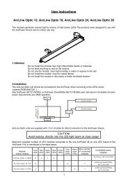
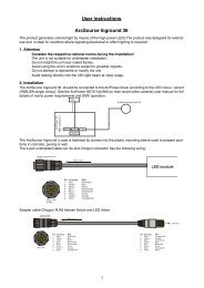
The maximum ambient temperature 40° C must never be exceeded.Operate the unit only after having familiarized with its functions. Do not permit operation by persons not qualifiedfor operating the unit. Most damages are the result of unprofessional operation!Please use the original packaging if the product is to be transported.Please consider that unauthorized modifications on the unit are forbidden due to safety reasons!3. Description of the <strong>Arc</strong><strong>Power</strong> <strong>384</strong> <strong>Rack</strong> <strong>Mount</strong>1 - LCD graphic displayr2 - ANS rotary wheel3 - Enter button4 - Escape buttont5 - Cooling fans1 - Fuse holder2 - Mains input3 - DMX IN/OUT (3-pin XLR)4 - DMX input for DyNet (RJ45)5 - Control port (RS 232)6 - LED Zones 1-8 (8 x RJ45)7 - Ethernet (RJ45)8 - DMX IN/OUT(5-pin XLR)
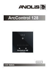
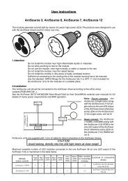
To build a DMX chain.1. Unplug fixtures from the mains before installation.2. Connect the LED modules to the fixtures.You cannot combine RGB and RGBW modules(e.g. <strong>Arc</strong>Source 6 RGB and <strong>Arc</strong>Source 7 RGBW) on the same LEDs output.3. Connect the DMX controller to the first fixture4. Connect fixtures each other. Max. 32 fixtures may be connected on a DMX link. Terminate the DMX linkby installing a termination plug in the output of the last fixture. The termination plug is a male 3-pin/5-pinXLR plug with a 120 Ohm resistor soldered between Signal (–) and Signal (+).5. Connect fixtures to the mains6. Set desired DMX address on each fixture (see the chapter "Control board").Note: You cannot combine RGB andRGBW modules on one LED output as the current circle of the white LEDswill not be closed ( white LEDs will not lit). All modules have to be either RGB or RGBW on one LED output..7. Ethernet operationThe fixtures on a data link are connected to the Ethernet network with an Art-Net communication protocol. Thecontrol software from PC (or lighting console) has to support the Art-Net protocol.The Art-Net communication protocol is a 10 Base T Ethernet protocol based on the TCP/IP. Its purpose is toallow transfer of large amounts of DMX 512 data over a wide area using standard network technology.An IP address is Internet protocol address. The IP uniquely identifies any node (fixture) on a network.The Universe is a single DMX 512 frame of 512 channels.The <strong>Arc</strong><strong>Power</strong> <strong>384</strong> <strong>Rack</strong> <strong>Mount</strong> is equipped with 8-pin RJ- 45 socket for Ethernet input. Use a network cable category5 (with four “twisted” wire pairs) and standard RJ-45 plugs in order to connect the fixture to the network.Patch cables that connect fixtures to the hubs or LAN sockets are wired 1:1, that is, pins with thesame numbers are connected together:
1-1 2-2 3-3 4-4 5-5 6-6 7-7 8-8If only the fixture and the computer are to be interconnected, no hubs or other active components are needed.A cross-cable has to be used:1-3 2-6 3-1 4-8 5-7 6-2 7-5 8-4All fixtures have to be connected to Ethernet via standard patch cables and a data switch.The option “ Ethernet” has to be selected from the “Set Ethernet Mode” menu on each fixture.Set correct IP address and the Universe for each fixture.
8. <strong>Arc</strong><strong>Power</strong> <strong>384</strong> <strong>Rack</strong> <strong>Mount</strong> - Control menu mapDefault settings=Bold printMenu Level 1 Menu Level 2 Menu Level 3 Menu Level 4 Menu Level 5 Menu Level 6Fixture Address DMX Address 001-512Dynet Zone 1-255Ethernet Settings Set Ethernet Mode Disable EthernetEthernetSet IP Address Default IP AddressCustom IP AddressSet ArtNet Universe 0-255Fixture Information <strong>Power</strong> On Time Total HoursResetable HoursAir Filters Set Alert Period 10...50...300 hoursElapsed timeFixture temperature Current Board 1 Temp.Board 2 Temp.Max. Nonresetable Board 1 Temp.Board 2 Temp.Maximum Resettable Board 1 Temp.Board 2 Temp.DMX Values Red LEDs 1 0-255:Dimmer 0-255Software Version IC1 MB1IC2 MB1IC1 MB2IC1 DSIC2 DSProduct IDsMac Adr.RDM UIDPersonality <strong>User</strong> Mode <strong>User</strong> A Settings<strong>User</strong> B Settings<strong>User</strong> C SettingsDMX Preset Mode 1 Ch.1 Red LEDs 1:Ch. 24 Blue LEDs 8Set ActiveMode 2 Ch.1 Red LEDs 1:Ch.32White LEDs 8Set ActiveMode 3 Ch.1 Red LEDs 1:Ch.35 DimmerSet ActiveMode 4 Ch.1 Red LEDs 1:Ch. 4 DimmerSet ActiveMode 5 Ch.1 Red LEDs 110
Menu Level 1 Menu Level 2 Menu Level 3 Menu Level 4 Menu Level 5 Menu Level 6Communication protocolDMXCh. 5 DimmerSet ActiveDYNETRS-232Display Adjusting Display Permanent On, OffOnDisplay Intensity 1..6..10Display Backlight 1..5...10Display Turned On, OffIR SensorOn, OffInit Effect Positions Red LEDs 1 0-255:Dimmer 0-255SaveTemperature Unit °C, °FWhite Balance On, OffWhite Balance SettingRed 0..200..255Green 0..........255Blue 0..237..255LEDs Output Current Zone 1 350mA: 700mAZone 8LEDs <strong>Power</strong> Limiting Zone 1 On, Off:Zone 8Default SettingTest SequencesTest program......Manual Mode Preset Effect Control RED LEDs 1 Intensity 1-10:DimmerManual Effect Control Pan 0-255:Dimmer 0-255Stand-alone SettingPreset Playback DisabledTest programProgram 1:Program 3Playing Program Test Program in LoopProgram 1 in Loop:Program 3 in LoopEditing Program Program 1 Edit Steps Step 1 Red LEDs 1 (0-255): : :Program 3 Step 99 Dimmer (0-255)Fade T.(0.1-25.5s)Step T.( 0.1-25s)11
Menu Level 1 Menu Level 2 Menu Level 3 Menu Level 4 Menu Level 5 Menu Level 6SaveSave and CopyStart Step Step1- Step 99End Step Step1- Step 99Special Functions Effect Adjustment DMX Values RED LEDs 1:DimmerInitial BlinkOn, OffUpdating Software12
9. <strong>Arc</strong><strong>Power</strong> <strong>384</strong> <strong>Rack</strong>-<strong>Mount</strong> - DMX protocolVersion 1.3Mode/Channel1 2 3 4 5 61 1 1 1 1 12 2 2 2 2 23 3 3 3 3 3- 4 4 - 4 4- - - - - 5- - - - - 64 5 5 1 1 75 6 6 2 2 86 7 7 3 3 9- 8 8 - 4 10- - - - - 11- - - - - 127 9 9 1 1 138 10 10 2 2 14Value Function Type of control0-2550-2550-2550-25501-151617-555657-959697-134135136-174175176-214215216-2542550-2550-2550-2550-2550-25501-151617-555657-959697-134135136-174175176-214215216-2542550-2550-2550-255ZONE 1Red LED 1Red LED saturation control (0-100%)Green LED 1Green LED saturation control (0-100%)Blue LED 1Blue LED saturation control (0-100%)White LED 1White LED saturation control (0-100%)Zone 1 colour macros selectionNo functionWhite tonesBlue=full, Red+Green+White=0Red=0, Green-->up,Blue =full, White=0Red=0, Green=full, Blue =full, White=0)Red=0, Green=full, Blue-->down, White=0Red=0, Green=full, Blue =0, White=0Red-->up, Green=full, Blue=0, White=0Red=full, Green=full, Blue=0, White=0Red=full, Green-->down, Blue=0, White=0Red=full, Green=0, Blue=0, White=0Red=full, Green=0, Blue-->up, White=0Red=full, Green=0, Blue=full, White=0Red-->down, Green=0, Blue=full, White=0Red=0, Green=0, Blue=full, White=0Dimmer 1Dimmer intensity from 0% to 100%ZONE 2Red LED 2Red LED saturation control (0-100%)Green LED 2Green LED saturation control (0-100%)Blue LED 2Blue LED saturation control (0-100%)White LED 2White LED saturation control (0-100%)Zone 2 colour macros selectionNo functionWhite tonesBlue=full, Red+Green+White=0Red=0, Green-->up,Blue =full, White=0Red=0, Green=full, Blue =full, White=0)Red=0, Green=full, Blue-->down, White=0Red=0, Green=full, Blue =0, White=0Red-->up, Green=full, Blue=0, White=0Red=full, Green=full, Blue=0, White=0Red=full, Green-->down, Blue=0, White=0Red=full, Green=0, Blue=0, White=0Red=full, Green=0, Blue-->up, White=0Red=full, Green=0, Blue=full, White=0Red-->down, Green=0, Blue=full, White=0Red=0, Green=0, Blue=full, White=0Dimmer 2Dimmer intensity from 0% to 100%ZONE 3Red LED 3Red LED saturation control (0-100%)Green LED 3Green LED saturation control (0-100%)proportionalproportionalproportionalproportionalstepproportionalstepproportionalstepproportionalstepproportionalstepproportionalstepproportionalstepproportionalstepproportionalproportionalproportionalproportionalproportionalstepproportionalstepproportionalstepproportionalstepproportionalstepproportionalstepproportionalstepproportionalstepproportionalproportionalproportional13
Mode/Channel1 2 3 4 5 69 11 11 3 3 15- 12 12 - 4 16- - - - - 17- - - - - 1810 13 13 1 1 1911 14 14 2 2 2012 15 15 3 3 21- 16 16 - 4 22- - - - - 23- - - - - 2413 17 17 1 1 2514 18 18 2 2 2615 19 19 3 3 27- 20 20 - 4 28Value Function Type of control0-2550-25501-151617-555657-959697-134135136-174175176-214215216-2542550-2550-2550-2550-2550-25501-151617-555657-959697-134135136-174175176-214215216-2542550-2550-2550-2550-2550-255Blue LED 3Blue LED saturation control (0-100%)White LED 3White LED saturation control (0-100%)Zone 3 colour macros selectionNo functionWhite tonesBlue=full, Red+Green+White=0Red=0, Green-->up,Blue =full, White=0Red=0, Green=full, Blue =full, White=0)Red=0, Green=full, Blue-->down, White=0Red=0, Green=full, Blue =0, White=0Red-->up, Green=full, Blue=0, White=0Red=full, Green=full, Blue=0, White=0Red=full, Green-->down, Blue=0, White=0Red=full, Green=0, Blue=0, White=0Red=full, Green=0, Blue-->up, White=0Red=full, Green=0, Blue=full, White=0Red-->down, Green=0, Blue=full, White=0Red=0, Green=0, Blue=full, White=0Dimmer 3Dimmer intensity from 0% to 100%ZONE 4Red LED 4Red LED saturation control (0-100%)Green LED 4Green LED saturation control (0-100%)Blue LED 4Blue LED saturation control (0-100%)White LED 4White LED saturation control (0-100%)Zone 4 colour macros selectionNo functionWhite tonesBlue=full, Red+Green+White=0Red=0, Green-->up,Blue =full, White=0Red=0, Green=full, Blue =full, White=0)Red=0, Green=full, Blue-->down, White=0Red=0, Green=full, Blue =0, White=0Red-->up, Green=full, Blue=0, White=0Red=full, Green=full, Blue=0, White=0Red=full, Green-->down, Blue=0, White=0Red=full, Green=0, Blue=0, White=0Red=full, Green=0, Blue-->up, White=0Red=full, Green=0, Blue=full, White=0Red-->down, Green=0, Blue=full, White=0Red=0, Green=0, Blue=full, White=0Dimmer 4Dimmer intensity from 0% to 100%ZONE 5Red LED 5Red LED saturation control (0-100%)Green LED 5Green LED saturation control (0-100%)Blue LED 5Blue LED saturation control (0-100%)White LED 5White LED saturation control (0-100%)proportionalproportionalstepproportionalstepproportionalstepproportionalstepproportionalstepproportionalstepproportionalstepproportionalstepproportionalproportionalproportionalproportionalproportionalstepproportionalstepproportionalstepproportionalstepproportionalstepproportionalstepproportionalstepproportionalstepproportionalproportionalproportionalproportionalproportional14
Mode/Channel1 2 3 4 5 6- - - - - 29- - - - - 3016 21 21 1 1 3117 22 22 2 2 3218 23 23 3 3 33- 24 24 - 4 34- - - - - 35- - - - - 3619 25 25 1 1 3720 26 26 2 2 3821 27 27 3 3 3928 28 - 4 40Value Function Type of control01-151617-555657-959697-134135136-174175176-214215216-2542550-2550-2550-2550-2550-25501-151617-555657-959697-134135136-174175176-214215216-2542550-2550-2550-2550-2550-255Zone 5 colour macros selectionNo functionWhite tonesBlue=full, Red+Green+White=0Red=0, Green-->up,Blue =full, White=0Red=0, Green=full, Blue =full, White=0)Red=0, Green=full, Blue-->down, White=0Red=0, Green=full, Blue =0, White=0Red-->up, Green=full, Blue=0, White=0Red=full, Green=full, Blue=0, White=0Red=full, Green-->down, Blue=0, White=0Red=full, Green=0, Blue=0, White=0Red=full, Green=0, Blue-->up, White=0Red=full, Green=0, Blue=full, White=0Red-->down, Green=0, Blue=full, White=0Red=0, Green=0, Blue=full, White=0Dimmer 5Dimmer intensity from 0% to 100%ZONE 6Red LED 6Red LED saturation control (0-100%)Green LED 6Green LED saturation control (0-100%)Blue LED 6Blue LED saturation control (0-100%)White LED 6White LED saturation control (0-100%)Zone 6 colour macros selectionNo functionWhite tonesBlue=full, Red+Green+White=0Red=0, Green-->up,Blue =full, White=0Red=0, Green=full, Blue =full, White=0)Red=0, Green=full, Blue-->down, White=0Red=0, Green=full, Blue =0, White=0Red-->up, Green=full, Blue=0, White=0Red=full, Green=full, Blue=0, White=0Red=full, Green-->down, Blue=0, White=0Red=full, Green=0, Blue=0, White=0Red=full, Green=0, Blue-->up, White=0Red=full, Green=0, Blue=full, White=0Red-->down, Green=0, Blue=full, White=0Red=0, Green=0, Blue=full, White=0Dimmer 6Dimmer intensity from 0% to 100%ZONE 7Red LED 7Red LED saturation control (0-100%)Green LED 7Green LED saturation control (0-100%)Blue LED 7Blue LED saturation control (0-100%)White LED 7White LED saturation control (0-100%)stepproportionalstepproportionalstepproportionalstepproportionalstepproportionalstepproportionalstepproportionalstepproportionalproportionalproportionalproportionalproportionalstepproportionalstepproportionalstepproportionalstepproportionalstepproportionalstepproportionalstepproportionalstepproportionalproportionalproportionalproportionalproportional15
Mode/Channel1 2 3 4 5 6- - - - - 41- - - - - 4222 29 29 1 1 4323 30 30 2 2 4424 31 31 3 3 45- 32 32 - 4 46- - - - - 47- - - - - 48- - 33 - 49Value Function Type of control01-151617-555657-959697-134135136-174175176-214215216-2542550-2550-2550-2550-2550-25501-151617-555657-959697-134135136-174175176-214215216-2542550-25501-151617-555657-959697-134135136-174175176-214215216-254255Zone 7 colour macros selectionNo functionWhite tonesBlue=full, Red+Green+White=0Red=0, Green-->up,Blue =full, White=0Red=0, Green=full, Blue =full, White=0)Red=0, Green=full, Blue-->down, White=0Red=0, Green=full, Blue =0, White=0Red-->up, Green=full, Blue=0, White=0Red=full, Green=full, Blue=0, White=0Red=full, Green-->down, Blue=0, White=0Red=full, Green=0, Blue=0, White=0Red=full, Green=0, Blue-->up, White=0Red=full, Green=0, Blue=full, White=0Red-->down, Green=0, Blue=full, White=0Red=0, Green=0, Blue=full, White=0Dimmer 7Dimmer intensity from 0% to 100%ZONE 8Red LED 8Red LED saturation control (0-100%)Green LED 8Green LED saturation control (0-100%)Blue LED 8Blue LED saturation control (0-100%)White LED 8White LED saturation control (0-100%)Zone 8 colour macros selectionNo functionWhite tonesBlue=full, Red+Green+White=0Red=0, Green-->up,Blue =full, White=0Red=0, Green=full, Blue =full, White=0)Red=0, Green=full, Blue-->down, White=0Red=0, Green=full, Blue =0, White=0Red-->up, Green=full, Blue=0, White=0Red=full, Green=full, Blue=0, White=0Red=full, Green-->down, Blue=0, White=0Red=full, Green=0, Blue=0, White=0Red=full, Green=0, Blue-->up, White=0Red=full, Green=0, Blue=full, White=0Red-->down, Green=0, Blue=full, White=0Red=0, Green=0, Blue=full, White=0Dimmer 8Dimmer intensity from 0% to 100%Common channels for all ZonesColour macros selectionNo functionWhite tonesBlue=full, Red+Green+White=0Red=0, Green-->up,Blue =full, White=0Red=0, Green=full, Blue =full, White=0)Red=0, Green=full, Blue-->down, White=0Red=0, Green=full, Blue =0, White=0Red-->up, Green=full, Blue=0, White=0Red=full, Green=full, Blue=0, White=0Red=full, Green-->down, Blue=0, White=0Red=full, Green=0, Blue=0, White=0Red=full, Green=0, Blue-->up, White=0Red=full, Green=0, Blue=full, White=0Red-->down, Green=0, Blue=full, White=0Red=0, Green=0, Blue=full, White=0stepproportionalstepproportionalstepproportionalstepproportionalstepproportionalstepproportionalstepproportionalstepproportionalproportionalproportionalproportionalproportionalstepproportionalstepproportionalstepproportionalstepproportionalstepproportionalstepproportionalstepproportionalstepproportionalstepproportionalstepproportionalstepproportionalstepproportionalstepproportionalstepproportionalstepproportionalstep16
Ethernet Settings --- The menu provides all needed settings for an Ethernet operation.Set Ethernet Mode - use the menu to set an Ethernet functional mode:Disable Ethernet - Disables an Ethernet operation.Ethernet - control data is received to the Ethernet input of the fixture ( RJ45 socket).Each of fixtures has to be connected to Ethernet.Set IP Address - Select this menu item to set an IP address. The IP address is theInternet protocol address, uniquely identifies any node (fixture) on a network.There can‘t be 2 fixtures with the same IP address on the network!Default IP Address - a preset IP address, you can change only first number ofthe IP address (number 2 or 10).Custom IP Address - a fully editable IP address.To set the custom IP address:1. Select the „Custom IP Address” and press the ENTER button2. Use RNS wheel to adjust he first number of the IP address3. Press the ENTER button to move on the second number of theIP address4. Repeat steps 2 and 3 for the third and the fourth number of theIP address.If you want to return back on the previous number, press the ESC button.Set ArtNet Universe - use this menu item to set a fixture Universe. The Universe is a singleDMX 512 frame of 512 channels.10.2 Fixture informationUse this menu to read useful information about the fixture status.<strong>Power</strong> On Time --- Use the menu item to read the number of operation hours.Total Hours - the function shows the total number of the operation hours sincethe <strong>Arc</strong><strong>Power</strong> <strong>384</strong> <strong>Rack</strong> <strong>Mount</strong> has been fabricated.Resettable Hours - the function shows the number of the operation hours thatthe <strong>Arc</strong><strong>Power</strong> <strong>384</strong> <strong>Rack</strong> <strong>Mount</strong> has been powered on since the counter was last reset.In order to reset this counter to 0, press the ENTER button twice.Air Filters --- Regular cleaning of the air filters is very important for the fixture´s life and performance. Build-upof dust, dirt and fog fluid residues reduces the fixture´s light output and cooling ability. The two items of thismenu help you to keep cleaning period of the air filters.Set alert period - cleaning schedule for the fixture depends on the operating environment.It is therefore impossible to specify accurate cleaning interval. This function allowsyou to change the cleaning interval of the air filters. This „alert“ value is 50 hours and itis set as default. Inspect the fixture within its 50 hours of operation to see whether cleaningis necessary. If cleaning is required, clean all air filters and change the value in this menuon acceptable level. Min. level of alert period is 10 hours, max. is 300 hours.Elapsed Time - the option allows you to read the time which remains to cleaning air filters.The time period is set in the menu mentioned above.Expired time period is signalized by a negative mark at the time value and a warning icon(triangle) on the display with the following message: „Clean Air Filters“.Clean the filters and reset this menu item (by pressing the ENTER button twice whilethis menu is highlighted) to start the new time countdown.Fixture Temperatures --- Select this menu to read the temperatures of the fixture:Current - the current temperature of the fixture inside.Maximum nonresettable - the menu item shows the max. temperatures of the fixture insidesince the <strong>Arc</strong><strong>Power</strong> <strong>384</strong> <strong>Rack</strong> <strong>Mount</strong>has been fabricated.Maximum resettable - the menu item shows the maximum temperatures of the fixtureinside since the counter was last reset. In order to reset desired counter to 0,pressthe ENTER button twice.Note: The ambient temperature should not exceed 40°C.The temperatures can be displayed in either °C or °F units - see option „Temperature unit“ in the menu “Personality“.Measuring temperature points: Board 1 Temp. - temperature on the electronic module 1.Board 2 Temp. - temperature on the electronic module 2.18
DMX Values --- Select this function to read DMX values of each channel received by the fixture.Software Version --- Select this function to read the software versions of the fixture processors:IC1 MB1 - the processor in the electronic module 1 controls LED zones 5-8.IC2 MB1 - EEprom on the electronic module 1.IC1 MB2 - the processor in the electronic module 1 controls LED zones 1-4.IC1 DS - the main display processor on the front panel of the fixture.IC2 DS - the display memory on the front panel of the fixture.Product IDS --- Select this function to read either the MAC address or the RDM UID figure.10.3 PersonalityUse this menu to modify the <strong>Arc</strong><strong>Power</strong> <strong>384</strong> <strong>Rack</strong> <strong>Mount</strong> operating behaviour.<strong>User</strong> mode --- The <strong>Arc</strong><strong>Power</strong> <strong>384</strong> <strong>Rack</strong> <strong>Mount</strong> allows you to recall up to 3 user settings. After switching thefixture on for the first time, the <strong>User</strong> A settings is active. Now all changes made in the “Personality” menu ,”Fixture Address” menu and the “ Presetting Playback“ menu from the “Stand-alone setting” are saved to the<strong>User</strong> A settings. If you now select the <strong>User</strong> B settings, from this moment the changes you makes will be savedto the <strong>User</strong> B settings. After switching the fixture off and on, the <strong>User</strong> B setting will be active. In this way youmay use the 3 fixture operating behaviours.<strong>User</strong> A Settings - the function recall the user A settings.<strong>User</strong> B Settings - the function recall the user B settings.<strong>User</strong> C Settings - the function recall the user C settings.DMX Preset --- Use this function to set desired channel setting. Please refer to the chapter “DMX protocol” fora detail description of each mode.Communication Protocol --- Select desired protocol: DMX, Dynet or RS-232.Display Adjusting --- This menu allows you to change the display settings.Display Permanent On - this function allows you to keep the display permanent on orto turn it off automatically 2 minutes after last pressing any button on the control panel.Display Intensity - select this function to adjust the display intensity (1 - min., 10 - max.).Display Backlight - select this function to adjust the display backlight (1- min., 10 - max.).Display Turned - select this function to turn the display by 180°.IR Sensor --- Select this function to switch on/off the infra-red remote control.Init Effect Positions --- Use this function to set all effects to the desired positions to which they will move afterswitching the fixture on (if DMX is not being received).Temperature Unit --- Use this menu in order to display the fixture temperatures in desired units: °C or °F.Balance --- Use this menu item to enable (On) or disable (Off) the white balance which is set in the „White colourbalance“ menu below. If this function is set Off, the <strong>Arc</strong><strong>Power</strong> <strong>384</strong> <strong>Rack</strong> <strong>Mount</strong> will use maximum values (255)of saturation for red, green and blue colour. This function has to be set on before adjusting a white balance.White Colour Balance --- The menu gives access to the setting of the white balance.To set white colour balance.1. Use a DMX controller or the “Manual Mode“ menu to set all LEDs on max. saturation.2. Use the RNS rotary wheel to find the “Personality“ menu.3. Press the ENTER button.4. Use the RNS rotary wheel to select the "White Balance Setting“ menu.5. Press the ENTER button and the "Red“ item will appear on the display.6. Press the ENTER button and use RNS rotary wheel to set new max. value for the red LEDs.7. Press the ENTER button to confirm the choice.8. Use the RNS rotary wheel to select next colour, "Green“.9. Repeat steps 6-7 for this channel.10. Use the RNS rotary wheel to select the last colour, "Blue “ and repeat steps 6-7 for this colour.19
LED Output Current --- The menu allows to set desired current output to each LED zone depending upused LEDsZone 1 – 350mA per channel for 1Watt LEDs (Cree MC-E RGBW multichips) or700mA per channel for Luxeon K2( ProLight Opto 3Watt Proeon)LEDs:Zone 8– 350mA per channel for 1Watt LEDs (Cree MC-E RGBW multichips) or700mA per channel for Luxeon K2( ProLight Opto 3Watt Proeon)LEDsWarning: Set the LED Output <strong>Power</strong> before connecting the LED modules to the driver. Never connect1Watt LEDs to the 700mA output otherwise these LEDs vill be destroyed.LEDs <strong>Power</strong> Limiting --- The menu item alows to reduce total current for desired zone. If option "Off" isselected, max. total current is allowed but for option "On" total current (sum of each channel currents) will bereduced to 1200 mA max.Important: If the <strong>Arc</strong><strong>Power</strong> <strong>384</strong> <strong>Rack</strong> <strong>Mount</strong> is used for control of the <strong>Arc</strong>Pad 48, two rules has to be kept:1. The LEDs power limiting has to be set On at zone for which is the <strong>Arc</strong>Pad 48 connected.2. The LEDs output current has to be set on 700mA at zone for which is the <strong>Arc</strong>Pad 48 connected.Default Settings --- The menu item sets all fixture parameters to the default (factory) values.10.4 Test sequencesUse this menu to run test program or user programs 1-3 without an external controller.10.5 Manual modePreset Effects --- Select this menu to call up preset channel effects.Manual Effect control --- Use this menu for full control of each channel effect.10.6 Stand-alone settingUse this menu to set options used in stand-alone mode, as a selection of the running program, programmingand modifying programs.Presetting Playback --- This function allows you to select the program which will be played after switching thefixture on. Selected program will be played in a loop.Disabled –the option disables the “Presetting playback” function.Test Program - The option will start built–in demo sequences.Program 1 - the option will start a program No.1.Program 2 - the option will start a program No. 2.Program 3 - the option will start a program No. 3.Note. If any program from this menu is has been selected and the fixture is switched off and on (and receivesa DMX signal), the fixture does not reply to DMX and will run this program.Playing program --- Use this menu to run a desired program in a loop.Test Program In Loop - the option starts built–in demo program.Program 1 In Loop - the option starts program No. 1.Program 2 In Loop - the option starts program No. 2.Program 3 In Loop - the option starts program No. 3.Select the program you wish to run and press the ENTER button. The selected program starts running. Bypressing the ENTER button again, the program will be paused.Editing Program --- Use this menu to edit or create program. The <strong>Arc</strong><strong>Power</strong> <strong>384</strong> <strong>Rack</strong> <strong>Mount</strong> has one built-inprogram and the 3 free programs, each up to 99 steps.Procedure:1. Use the RNS rotary wheel to find the “ Stand-alone setting“menu and press the ENTER button.2. Use the RNS rotary wheel to select the “ Editing Program“menu and press the ENTER button.3. Select the program you want to edit (“Program 1” - “Program 3”) and press the ENTER button.4. Select the “Edit Steps” menu and press [ENTER].5. Select the desired program step (“Step 01” - “Step 99”) and press the ENTER button.6. Now you can edit DMX values for selected items:“Red LEDs 1”- saturation of red LEDs, DMX value from 0-255.20
:“Fade Time” – the time, during during which effects go to the current step, value from 0-25.5 sec.“Step Time” - the time, during which effects last in the current step, value from 0-25.5s7. After editing all desired item, select “Save” or “Save and Copy” and press the ENTER button.“Save” - saving the current prog. step.“Save and Copy” - saving and copying the current prog. step to the next prog. step.8. Go on next program step and repeat instructions 6-7.9. After creation the program, enter the “Start Step” menu and adjust the first step of the program.10. Enter the “End Step” menu and adjust the last step of the created program.Note: you can simply reduce the program length by changing values in either “Start Step” or “End Step”menu.10.7 Special FunctionsEffect Adjusting --- the menu enables to set all fixture effects to the desired positions.Initial Blink --- If the item is on, autocalibration of the fixture will run after switching the fixture on (or reset thefixture or changing LED ouput power 300mA-->700mA, 700mA-->300mA).Updating Software ---The menu item allows you to update software in the fixture via either serial or USB portof PC.The following are required in order to update software:- PC running Windows 95/98/2000/XP or Linux- DMX Software Uploader- Flash cable RS232/DMX No.13050624 (if you will use a serial port of PC)- RObe universal Interface (if you will use an USB port of PC)Note1: Software update should execute a qualified person. If you lack qualification, do not attempt the updateyourselfand ask for help your ROBE distributor.Note 2: DMX address, IP address, programs 1-3 and all items in the menu „Personality“ will be set to theirdefault (factory) values.To update software in the fixture:I. Installation of the DMX Software Uploader.1. DMX Software Uploader program is available from the <strong>Anolis</strong> web site at WWW.anolis.cz.2. Make a new directory ( e.g. <strong>Anolis</strong>_Uploader) on your hard disk and download the software to it.3. Unpack the program from the archive.II.Fixture software updating.1.Determine which of your ports is available on your PC and connect it:- with the DMX input of the fixture if you using the flash cable RS232/DMX- with the USB input of the Robe Universal Interface if you using the USB cable.Disconnect the fixture from the other fixtures in a DMX chain. Turn both the computer and thefixture on.2. Switch the fixture to the updating mode:1. Use the RNS rotary wheel to find the “ Special Functions“ menu.. Press the ENTER button.3. Use the RNS rotary wheel to select the “Updating Software“ item.4. Press the ENTER button.5. Use the RNS rotary wheel to select “ Yes“ option.6. Press the ENTER button.Note: If you do not want to continue in software update, you have to switch off and on the fixtureto escape from this menu.We recommend to cancel all running programs before start the Software Uploader.3. Run the Software Uploader program. Select desired COM and then click on the Connect button(Select COM if the serial port is used or DreamBox1 if the USB port is used).If the connection is OK, click on the “Start Uploading button“ to start uploading. It will takeseveral minutes to perform software update.If the option „Incremental Update“ is not checked, all processors will be updated (includingprocessors with the same software version).If you wish to update only later versions of processors, check the “Incremental Update box“.Avoid interrupting the process. Update status is being displayed in the Info Box window.When the update is finished, the line with the text “The fixture is successfully updated“ will appear inthis window and the fixture will reset with the new software.Note: In the case of an interruption of the upload process (e.g. power cut), the fixture keeps the updating modeand you have to repeat the software update again. 21
11.Technical Specifications:<strong>Power</strong> supplyInput voltage: 100-240V AC, 50/60 HzMax. power consumption at 230V: 520 W/540VA (350mA LED outputs), power factor = 0.961200W/1250VA (700 mA LED outputs) , power factor = 0.96Main fuse: T 8A H @230V, T 12A @120VOutputMax.Output current:350mA or 700 mA per colourNumber of LED zones: 8Max. load per zone (1W LEDs or ProLight Opto 3Watt Proeon LEDs) :36 LEDs in RGB mode48 LEDs in RGBW mode1 x <strong>Arc</strong>Pad 48Total load (1W LEDs or ProLight Opto 3Watt Proeon LEDs):288 LED´s in RGB mode<strong>384</strong> LEDs in RGBW mode8 x <strong>Arc</strong>PadMaximum total cable length between one LED zone output and connected LED module1W LEDs: 80 metresProLight Opto 3Watt Proeon LEDs: 20 metres<strong>Arc</strong>Pad 48: 40 metres (connecting cable Igus with Chogori-Cogori connectors has to be used)DMX control channelsMode 1: 24 channelsMode 2: 32 channelsMode 3: 35 channelsMode 4: 4 channelsMode 5: 5 channelsMode 6: 51 channelsTerminalsLEDs: RJ45DMX data in/out: Locking 3-pin and 5-pin XLRDyNet: RJ45Ethernet: RJ45RS232: DE-9 (male)AC power input: Neutrik <strong>Power</strong>Con, A-type, NAC3MPAControl & ProgrammingSetting and addressing: ANS (<strong>Anolis</strong> navigation system)Display: blue/white LCD graphicControl options: DMX, Art-NetStand alone operation3-editable programs up to 99 steps eachWhite colour balance adjustingManual control of all DMX channels via control panelOperating temperature range0°C/+40°CMax. surface temperature70°C22
Total heat dissipation (calculated)1700 BTU/h at 350mA LED outputs4000 BTU/h at 700 mA LED outputsDimensions (mm)Weight9.7 kgAccessoriesCable joiner (No.13050691)...............8 pcsOptional accessoriesRemote control IR (No. 13050419)Flash Cable RS232/DMX (No. 13050624)23
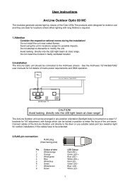
12. Maintenance12.1 Replacing the air filtersThe <strong>Arc</strong><strong>Power</strong> <strong>384</strong> <strong>Rack</strong> <strong>Mount</strong> is supplied with 2 air filters placed in front panel of the fixture.To replace the air filters.1. Disconnect the fixture from mains.2. Remove the protective grid (1) from the front panel by unscrewing the 4 screws.3. Remove the filter holding section (3)3. Pull out the air filter (3).4. Clean or replace the air filter (clean the air filters with a vacuum cleaner or you can wash them and putback dry).5. Put the filters cover back to the protective grid and secure them by he filter holding section.6. Screw up the protective grid (1) to the front panel.7. Repeat the same procedure for the second fan.8. Reset the item „Elapsed Time“ in the „Fixture Information“ (Fixture Information--> Air Filters-->ElapsedTime).12.2 Replacing the main fuseOnly replace the fuse by the one of the same type and rating.To replace the fuse.1. Disconnect the fixture from mains.2. Unscrew the fuse holder on the rear panel of the fixture with a fitting screwdriver from the housing (anticlockwise).3. Remove the old fuse from the fuse holder.4. Install the new fuse in the fuse holder.5. Replace the fuse holder in the housing and screw it.Specifications are subject to change without notice.March 30, 201524