Create successful ePaper yourself
Turn your PDF publications into a flip-book with our unique Google optimized e-Paper software.
version 1.2
ArcPower 48 MC<br />
Table of contents<br />
1. Safety instructions.......................................................................................................... 3<br />
2. Operating determinations.............................................................................................. 3<br />
3.Description of the ArcPower 48 MC............................................................................... 4<br />
4.Installation........................................................................................................................ 4<br />
4.1.Connection to the mains............................................................................................. 4<br />
4.2.Mounting the ArcPower 48 MC................................................................................... 5<br />
5.Installing instructions...................................................................................................... 5<br />
5.1.DMX operating............................................................................................................ 5<br />
5.2.Master-slave operating............................................................................................... 6<br />
6.ArcPower 48 MC - DMX protocol ................................................................................... 7<br />
7.Control board................................................................................................................... 8<br />
7.1 Fixture Address .......................................................................................................... 8<br />
7.2 Fixture information...................................................................................................... 8<br />
7.3 Personality.................................................................................................................. 9<br />
7.4 Manual mode............................................................................................................ 10<br />
7.5 Test sequences........................................................................................................ 10<br />
7.6 Stand-alone setting .................................................................................................. 10<br />
7.7 Special functions....................................................................................................... 11<br />
8.Technical Specifications:.............................................................................................. 13<br />
9 Replacing the fuse ........................................................................................................ 13
CAUTION!<br />
Unplug mains lead before opening the housing!<br />
FOR YOUR OWN SAFETY, PLEASE READ THIS USER MANUAL CAREFULLY<br />
BEFORE YOU INITIAL START - UP!<br />
1. Safety instructions<br />
Every person involved with installation and maintenance of this product has to:<br />
- be qualilfied<br />
- follow the instructions of this manual<br />
CAUTION!<br />
Be careful with your operations. With a high voltage you can suffer<br />
a dangerous electric shock when touching the wires inside the unit!<br />
This product has left our premises in absolutely perfect condition. In order to maintain this condition and to<br />
ensure a safe operation, it is absolutely necessary for the user to follow the safety instructions and warning<br />
notes written in this manual.<br />
To prevent from danger of accident ,the device has to be fixed on flat, non-flammable<br />
surface in compliance with the installing instruction included in this manual.<br />
Important:<br />
The manufacturer will not accept liability for any resulting damages caused by the non-observance of this<br />
manual or any unauthorized modification to the product.<br />
Always ground the unit.<br />
The electric connection, repairs and servicing must be carried out by a qualified employee.<br />
Do not connect this unit to a dimmer pack.<br />
Use a source of AC power that complies with local building and electrical rules.AC power has to have both<br />
overload and short circuit protection.<br />
2. Operating determinations<br />
The fixture is intended for indoor use only.<br />
If the unit has been exposed to drastic temperature fluctuation (e.g. after transportation), do not switch it on<br />
immediately. The arising condensation water might damage your unit. Leave the unit switched off until it has<br />
reached room temperature.<br />
Avoid brute force when installing or operating the unit.<br />
When choosing the installation-spot, please make sure that the unit is not exposed to extreme heat, moisture<br />
or dust.<br />
Only operate the unit after having checked that the housing is firmly closed and all screws are tightly fastened.<br />
The maximum ambient temperature 40° C must never be exceeded.<br />
Operate the unit only after having familiarized with its functions. Do not permit operation by persons not qualified<br />
for operating the unit. Most damages are the result of unprofessional operation!<br />
Please use the original packaging if the product is to be transported.<br />
Please consider that unauthorized modifications on the unit are forbidden due to safety reasons!
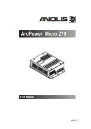
3.Description of the ArcPower 48 MC<br />
1 - LED display<br />
2 - Control buttons<br />
3 - DMX Output<br />
4 - DMX Input<br />
5 - LED Output<br />
6 - Fuse holder<br />
7 - Power cord<br />
DMX Input<br />
front view of the socket<br />
Pin 1: Shield<br />
Pin 2: Signal +<br />
Pin 3: Signal -<br />
DMX Output<br />
front view of the socket<br />
RJ45 socket<br />
front view of the socket:<br />
LED Output<br />
Pin 1: Thermal sensor Pin 5: Red LEDs -<br />
Pin 2: Thermal sensor Pin 6: Green LEDs -<br />
Pin 3: Red&Green LEDs + Pin 7: Blue LEDs -<br />
Pin 4: Blue&White LEDs + Pin 8: White LEDs -<br />
4.Installation<br />
4.1.Connection to the mains<br />
The ArcPower 48 MC is equipped with auto-switching power supply that automatically adjusts to any 50-60Hz<br />
AC power source from 100-240 Volts.<br />
Carefully prepare the end of the the supply cord and fit a suitable plug.A 3-prong grounding-type plug must be
installed following the manufacturer´s instructions.The earth has to be connected!<br />
Cord plug connections:<br />
Cable Pin International<br />
Brown Live L<br />
Light blue Neutral N<br />
Yellow/Green<br />
Earth<br />
This device falls under protection class I.Therefore the ArcPower 48 MChas to be<br />
connected to a mains socket outlet with a protective earthing connection.<br />
4.2.Mounting the ArcPower 48 MC<br />
The ArcPower 48 MC should be be placed on a non-flammable flat surface in any orientation and fixed by the<br />
two screws.There are two mounting holes of diameter 5 mm in housing of the driver. Ensure that instalation<br />
place is enough ventilated.<br />
Screw<br />
Screw<br />
Flat surface<br />
Mounting hole<br />
5.Installing instructions.<br />
5.1.DMX operating<br />
1.Unplug from the mains before installation.<br />
2.Connect the LED module to the fixture.<br />
3.Connect DMX controller to the fixture<br />
4.Connect the fixture to the mains<br />
5.Set the DMX address on the control board of the fixture (see chapter "Control board").<br />
Warning!<br />
Maximum total cable length between the ArcPower 48 MC and connected LED<br />
module can be 20 metres.
Connect the DMX output of the first ArcPower 48 MC with the DMX input of the next ArcPower 48. Always<br />
connect one output with the input of the next ArcPower 48 MC until all fixtures are connected.In this way,up to<br />
32 fixtures can be chained together.<br />
At the last ArcPower 48 MC the data link has to be terminated with a terminator. A termination plug is simply<br />
a XLR connector with a 120 Ω resistor between pins Data (–) and Data (+).Plug terminator in the DMX output<br />
of the last ArcPower 48.<br />
5.2.Master-slave operating<br />
1.Unplug from the mains before installation.<br />
2.Connect the LED module to the drivers.<br />
3.Connect the DMX output of the master fixture in the data-chain with the DMX input of the first slave. Always<br />
connect output with the input of the next slave until all slaves are connected.Up to 32 fixtures can be connected<br />
in master/slave chain<br />
4.Insert the termination plug (with 120 Ohm) into DMX input of the master fixture and into the DMX output of<br />
the last slave fixture in the link in order to ensure proper transmission on the data link.<br />
5.Connect the fixtures to the mains.<br />
6.See chapter "Stand-alone mode" in order to set the fixture as a master or slave.
6.ArcPower 48 MC - DMX protocol<br />
version 1.0<br />
Mode/Channel<br />
1 2 3 4<br />
Value<br />
Function<br />
Type<br />
of control<br />
- 1 1 1<br />
0-255<br />
RED LEDs<br />
Red LEDs saturation control (0-100%)<br />
proportional<br />
- 2 2 2<br />
0-255<br />
GREEN LEDs<br />
Green LEDs saturation control (0-100%)<br />
proportional<br />
- 3 3 3<br />
0-255<br />
BLUE LEDs<br />
Blue LEDs saturation control (0-100%)<br />
proportional<br />
- - 4 4<br />
0-255<br />
WHITE LEDs<br />
White LEDs saturation control (0-100%)<br />
proportional<br />
1 - - 5<br />
0<br />
1-15<br />
16<br />
17-55<br />
56<br />
57 - 95<br />
96<br />
97 – 134<br />
135<br />
136 - 174<br />
175<br />
176 -214<br />
215<br />
216 - 254<br />
255<br />
Colour macros (255 values)<br />
No function (for DMX mode 4)<br />
White (for DMX mode 1)<br />
White tones (cool-->warm)<br />
Blue (Blue=full, Red+Green+White=0)<br />
Red=0, Green-->up,Blue =full, White=0<br />
Light Blue (Red=0, Green=full, Blue =full, White=0)<br />
Red=0, Green=full, Blue-->down, White=0<br />
Green (Red=0, Green=full, Blue =0, White=0)<br />
Red-->up, Green=full, Blue=0, White=0<br />
Yellow-green (Red=full, Green=full, Blue=0, White=0)<br />
Red=full, Green-->down, Blue=0, White=0<br />
Red(Red=full, Green=0, Blue=0, White=0)<br />
Red=full, Green=0, Blue-->up, White=0<br />
Magenta (Red=full, Green=0, Blue=full, White=0)<br />
Red-->down, Green=0, Blue=full, White=0<br />
Blue (Red=0, Green=0, Blue=full, White=0)<br />
step<br />
proportional<br />
step<br />
proportional<br />
step<br />
proportional<br />
step<br />
proportional<br />
step<br />
proportional<br />
step<br />
proportional<br />
step<br />
proportional<br />
step<br />
- - - 6<br />
0-31<br />
32-63<br />
64-95<br />
96-127<br />
128-143<br />
144-159<br />
160-191<br />
192-223<br />
224-255<br />
SHUTTER/STROBE<br />
Shutter closed<br />
Shutter open<br />
Strobe-effect from slow to fast<br />
Shutter open<br />
Opening pulses in sequences slow--> fast<br />
Closing pulses in sequences fast --> slow<br />
Shutter open<br />
Random strobe-effects from slow to fast<br />
Shutter open<br />
step<br />
step<br />
proportional<br />
step<br />
proportional<br />
proportional<br />
step<br />
proportional<br />
step<br />
2 - - 7<br />
0-255<br />
DIMMER<br />
Dimmer intensity from 0% to 100%<br />
proportional<br />
- - - 8<br />
DIMMER FINE<br />
Dimmer intensity fine from low to high<br />
proportional
7.Control board<br />
The control panel situated on the top cover of the ArcPower 48 MC allows DMX addressing,calling build-in<br />
programs and setting the fixture behaviour<br />
The four control buttons on the front have the following functions:<br />
- ESCAPE button-leaves menu without saving changes.<br />
- ENTER button- enters menu, confirms adjusted values and leaves menu.<br />
- UP and - DOWN buttons - move between menu items on the same level, sets values.<br />
After switching the fixture on, the fixture display shows the current DMX address:<br />
Use the UP/DOWN buttons to scroll through the various menu items. To select desired item, press the EN-<br />
TER.<br />
7.1 Fixture Address<br />
Use this menu to set the DMX address of the fixture or set the fixture as a Master (Slave).<br />
dM.Ad. --- DMX addressing. Select this submenu to set a DMX start address.<br />
To set a DMX address.<br />
1. Use the UP/DOWN buttons to find “ A001“ menu.<br />
2. Press the ENTER button.<br />
3. Use the UP/DOWN buttons to select desired start address.<br />
4. Press the ENTER button to confirm the choice.<br />
MA.SL. --- Master/slave addressing. Select this submenu to set the fixture as a master or slave. Option "d.AbL"<br />
deactivates master/slave setting.<br />
To set a fixture as a master or slave.<br />
1. Use the UP/DOWN buttons to find “A001“ menu.<br />
2. Press the ENTER button.<br />
3. Use the UP/DOWN buttons to select “ MA.SL.“ item.<br />
4. Press the ENTER button.<br />
5. Use the UP/DOWN buttons to select either master (MASt) or slave (SLA)<br />
6. Press the ENTER button to confirm the choice.<br />
Note: After switching on, the ArcPower 48 MC will automatically detect whether DMX 512 data is received or<br />
not.<br />
If there is no data received at the DMX input, the display will start to flash with actually set address.<br />
7.2 Fixture information<br />
Use this menu to read useful information about the fixture status.<br />
To display desired information.<br />
1. Use the UP/DOWN buttons to find the “ InFo“ menu.<br />
2. Press the ENTER button.<br />
3. Use the UP/DOWN buttons to select the required menu item.<br />
4. Press the ENTER button to confirm the choice.<br />
Po.ti. --- Power On Time. Use the menu item to read the number of operation hours for each LEDs operating<br />
mode.<br />
totL - the function shows the total number of the operation hours since the ArcPower 48<br />
has been fabricated.<br />
rESEt - the function shows the number of the operation hours that the ArcPower 48 MC<br />
has been powered on since the counter was last reset. In order to
eset this counter to 0 you have to press and hold the UP and DOWN buttons and at the<br />
same time press the ENTER button.<br />
DM.In.---DMX values. Select this function to read DMX values of each channel received by the fixture.<br />
tEMP --- Fixture Temperature. Select this menu to read the temperature of the fixture:<br />
Cur.t. --- the current temperature:<br />
LEdS--- temperature of the LED module inside.<br />
boAr.--- temperature of the fixture inside.<br />
Hi.tE. - the menu item shows the max. temperatures since the ArcPower 48 MC<br />
has been fabricated.<br />
rSEt --- the menu item shows the maximum temperatures since the counter was last reset.<br />
In order to reset this counter to 0 you have to press and<br />
hold the UP and DOWN buttons and at the same time press the ENTER button.<br />
The temperatures can be displayed in either °C or °F units - see option “tEM.U“ in the menu “Pers“.<br />
VErS. ---Software Versions. Select this function to read the software version of the fixture processor.<br />
7.3 Personality<br />
Use this menu to modify the ArcPower 48 MC operating behaviour.<br />
DM.Pr. --- DMX preset. Select this menu item to set a desired DMX mode. Please refer to the chapter "DMX<br />
protocol" for detail description of each DMX mode.<br />
DiSP. --- Display adjusting. This function allows you to change the display settings.<br />
d.On --- this function allows you to keep the display on or to turn off automatically 2 minutes<br />
after last pressing any button on the control panel.<br />
d.Int. --- select this function to adjust the display intensity (30-min.,100-max.).<br />
turn --- select this function to turn the display by 180°.<br />
tEM.U. --- Temperature Unit. Use this menu in order to display the fixture temperatures in desired units: °C<br />
or °F.<br />
bALA --- Balance. Use this menu item to enable (On) or disable (Off) the white balance which is set in the “White<br />
colour balance“ menu below. If this function is set off, the ArcPower 48 MC will use maximum values (255) of<br />
saturation for red, green and blue colour. This function has to be set on before adjusting a white balance.<br />
C.bAL. --- White Colour Balance. The menu gives access to the setting of the white balance.<br />
To set white colour balance.<br />
1. Use a DMX controller or the “ Man.C.“ menu to set all LEDs on max. saturation.<br />
2. Use the UP/DOWN buttons to find the “ Pers.“ menu.<br />
3. Press the ENTER button.<br />
4. Use the UP/DOWN buttons to select the “C.bAL“menu.<br />
5. Press the ENTER button and the “rEd“ item will appear on the display.<br />
6. Press the ENTER button and use the UP/DOWN buttons to set new max. value for the red LEDs.<br />
7. Press the ENTER button to confirm the choice.<br />
8. Use the UP/DOWN buttons to select next colour, the “GrEn“.<br />
9. Repeat steps 6-7 for this channel.<br />
10. Use the UP/DOWN buttons to select the last colour, the „bLuE“ and repeat steps 6-7 for this colour.<br />
In.Po. --- Init effect positions. Use this function to set all effects to the desired positions to which they will<br />
move after switching the fixture on (if DMX is not being received).<br />
Note. If DMX mode 1 is selected, only values set at items “MACr” (macro) and dinr (dimmer) will be accepted.<br />
dF.SE. --- Default Settings .The menu item sets all fixture parameters to the default (factory) values.
7.4 Manual mode<br />
Use this menu for control the fixture without connected DMX console.<br />
PrE.C. --- Preset effects control. Select this menu to call up preset positions of the channel effects.<br />
Man.C. --- Manual effect control. Select this menu to control all channels via buttons of the control board.<br />
To control fixture channels.<br />
1. Use the UP/DOWN buttons to find “ Man.C“ menu.<br />
2. Press the ENTER button.<br />
3. Use the UP/DOWN buttons to select desired effect (channel).<br />
List of control channels:<br />
“rEd1” - red LEDs saturations<br />
“GrE1“ - green LEDs saturations<br />
“bLu1“ - blue LEDs saturations<br />
“Whi1“ - white LEDs saturations<br />
“MACr“ - colour macros<br />
“Stro.“ - a strobe, shutter<br />
“dimr“ - a dimmer<br />
“F.dim” a fine dimmer<br />
4. Press the ENTER button and use the UP/DOWN buttons to set value , press the ENTER button to<br />
confirm it.<br />
7. 5 Test sequences<br />
Use this menu to run demo-test sequences without an external controller, which will show you some possibilities<br />
of using the ArcPower 48 MC .<br />
7.6 Stand-alone setting<br />
The fixtures on a data link are not connected to the controller but can execute pre-set programs which can<br />
be different for every fixture. “Stand-alone operation” can be applied to the single fixture or to multiple fixtures<br />
operating synchronously.<br />
Synchronous operation of multiple fixtures requires that they must be connected on a data link and one of<br />
them is set as a master (“MASt“) and the rest as the slaves (“SLA“). Up to 32 fixtures can be connected in a<br />
master/slave chain. Only one fixture can be set as the master.<br />
Note: Disconnect the fixtures from the DMX controller before master/slave operating, otherwise data collisions<br />
can occur and the fixtures will not work properly. See the chapters “Stand-alone operation“ and “ Master/slave<br />
connection“.<br />
Auto. --- Automatic playback. This function allows you to select the program which will be played after switching<br />
the fixture on. Selected program will be played continuously in a loop.<br />
1. Use the UP/DOWN buttons to find “ St.AL.“ menu.<br />
2. Press the ENTER button.<br />
3. Use the UP/DOWN buttons to select “ Auto“ item.<br />
4. Press the ENTER button.<br />
5. Use the UP/DOWN buttons to select desired program.<br />
6. Press the ENTER button to confirm the choice.<br />
PLAY --- Playing program. By enter to this menu a complete overview of all programs is offered, from which<br />
the program to be run can be selected.<br />
1. Use the UP/DOWN buttons to find “ St.AL.“ menu.<br />
2. Press the ENTER button.<br />
3. Use the UP/DOWN buttons to select desired program.<br />
10
4. Press the ENTER button. The selected program runs in a loop.<br />
Edit --- Editing a program. The fixture offers 3 freely editable programs (EPG.1-EPG.3) each up to 68 steps.<br />
Every program step includes a fade time-the time taken by the step´s channel status to reach the desired level<br />
and a step time-the total time occupied by the step in the program.<br />
E.g. If “F.tim.“=5 second and “S.tim.“=20 second, effects will go to the desired position during 5 seconds and<br />
after that they will stay in this position for 15 seconds before going to the next prog. step<br />
1. Use the UP/DOWN buttons to find “ St.AL.“ menu and press the ENTER button.<br />
2. Use the UP/DOWN buttons to select “Edit“ menu and press the ENTER button.<br />
3. Use the UP/DOWN buttons to select a program you want to edit (PrG.1-PrG.3 and press ENTER<br />
button.<br />
4. Use the UP/DOWN buttons to select a desired program step ("St.01" - "St.68") and press ENTER<br />
button.<br />
5. Use the UP/DOWN buttons to select a channel you want to edit and press the ENTER button.<br />
List of editable items:<br />
“P.End” - a total number of the program steps (value 1-68). This value should be set before start<br />
Programming (e.g. if you want to create program with 10 steps, set P.End=10).<br />
“rEd1”- a red LEDs saturation (0-255)<br />
“GrE1“ - a green LEDs saturation (0-255)<br />
“bLu1“ -a blue LEDs saturation (0-255)<br />
“Whi1“ - “Whi4“ – a white LEDs saturation (0-255)<br />
“MACr“ - colour macros (0-255)<br />
“Stro.“ - a strobe, shutter (0-255)<br />
“dimr“ - a dimmer (0-255)<br />
“F.dim”- a fine dimmer (0-255)<br />
“F.tim.“ - a fade time, (0-25.5) seconds<br />
“S.tim.“ - step time, value (0-25.5) seconds<br />
“COPY“. – this item duplicates the current prog. step to the next prog. step. The item “P.End” is increased<br />
automatically.<br />
6. Use the UP/DOWN buttons to set a DMX value of the channel and then press the ENTER button.<br />
7. Use the UP/DOWN buttons to select next channel and press the ENTER button.<br />
8. After having set all channels in the current program step, press the MODE button to go by one<br />
menu level back and select another program step.<br />
7.7 Special functions<br />
rdML --- Code.This menu item shows the first part of the RDM identification code.<br />
rdMH --- Code. This menu item shows the second part of the RDM identification code.<br />
AdJ --- Effect Adjustment. The menu allows calibration of each LEDs array.<br />
dMH --- DMX Values. The menu item enables to control all LEDs before calibrating each<br />
LEDs array.<br />
CAL.U --- Calibrating unit. The menu serves for fine current calibration of LEDs during fixture<br />
burn-in at a factory. Users should not change the setting.<br />
uPd.M. --- Updating mode. The menu item allows you to update software in the fixture via either serial or USB<br />
port of PC.<br />
The following are required in order to update software:<br />
- PC running Windows 95/98/2000/XP or Linux<br />
- DMX Software Uploader<br />
- Flash cable RS232/DMX No.13050624 (if you want to use a serial port of PC)<br />
- Robe Universal Interface (if you want to use an USB port of PC)<br />
Note1: Software update should execute a qualified person. If you lack qualification, do not attempt the update<br />
yourself and ask for help your ROBE distributor.<br />
Note 2: DMX address, programs 1-3 and all items in the menu "PErS" will be set to their default values.<br />
To update software in the fixture:<br />
11
I. Installation of the DMX Software Uploader.<br />
1. DMX Software Uploader program is available from the <strong>Anolis</strong> web site at WWW.anolis.cz.<br />
2. Make a new directory ( e.g. Robe_Uploader) on your hard disk and <strong>download</strong> the software into it.<br />
3. Unpack the program from the archive.<br />
II.Fixture software updating.<br />
1. Determine which of your port is available on your PC and connect it:<br />
- with the DMX input of the fixture if you using the flash cable RS232/DMX<br />
- with the DMX input of the Robe Universal Interface if you using the USB cable.<br />
Disconnect the fixture from the other fixtures in a DMX chain. Turn both the computer and the fixture on. Make<br />
sure the lamp is switched off (only if the fixture involves a lamp).<br />
2. Switch the fixture to the updating mode:<br />
1 Use the UP/DOWN buttons to find “SPEC.“ menu.<br />
2 Press the ENTER button.<br />
3 Use the UP/DOWN buttons to select “ uPd.“ item.<br />
4 Press the ENTER button<br />
5 Use the UP/DOWN buttons to select “ yES“ option<br />
6 Press the ENTER button<br />
Note: If you do not want to continue in software update, you have to switch off and on the fixture<br />
to escape from this menu.<br />
3. We recommend to cancel all running programs before start of the Software Uploader.<br />
4. Run the Software Uploader program. Select desired COM and then click on the Connect button.<br />
If the connection is OK, click on the Start Uploading button to start uploading. It will take several minutes<br />
to perform software update. If the option "Incremental Update" is not checked, all processors will be<br />
updated (including processors with the same software version).<br />
If you wish to update only later versions of processors, check the Incremental Update box.<br />
Avoid interrupting the process. Update status is being displayed in the Info Box window.<br />
When the update is finished, the line with the text “The fixture is successfully updated‘will appear in<br />
this window and the fixture will reset with the new software.<br />
Note: In the case of an interruption of the upload process (e.g. power cut), the fixture keeps the updating mode<br />
and you have to repeat the software update again.<br />
For example: The fixture was switched off before finishing software upload. After switching again the fixture<br />
on, the fixture is still in the updating mode and the display is dark. Restart the Software Uploader program and<br />
repeat software update from your PC.<br />
12
8.Technical Specifications:<br />
Power supply:<br />
Input Voltage: version:100-240 V AC, 50/60 Hz<br />
Fuse:T 3.15A<br />
Max.Pover Consumption:130 W<br />
Input:<br />
Control:DMX 512<br />
DMX IN/OUT: 3-pin XLR<br />
Output:<br />
Max.Output Voltage:48V DC<br />
Max.Output current per colour channel : 700mA<br />
Connector: RJ45<br />
Max.load: 12 x 10W RGBW LED multichips<br />
Maxi. cable length between ArcPower 48 MC and LED module: 20 metres<br />
Control and programming:<br />
Control panel: 4-digit LED display and four control buttons<br />
Control: USITT DMX 512<br />
DMX protocol modes: 4 (2,3,4, 8 control channels)<br />
Operations modes: DMX, Stand-alone, Master/Slave<br />
Manual control of all effects via control panel<br />
3 user editable programs each up to 68 steps<br />
Operating temperature:<br />
-10°C/+40°C<br />
Dimensions(mm):<br />
Weight:<br />
1.8kg<br />
9 Replacing the fuse<br />
1.Before replacing the fuse, unplug mains lead!<br />
2.Unscrew the fuse holder on the rear side of the ArcPower 48 MCwith a fitting screwdriver from the housing<br />
(anti-clockwise).<br />
3.Remove the old fuse from the fuse holder.<br />
4.Install the new fuse in the fuse holder.<br />
5.Replace the fuse holder in the housing and fix it.<br />
Specifications are subject to change without notice.<br />
November 28, 2011<br />
13