SYNERGY⢠- Bonerepmedical.com
SYNERGY⢠- Bonerepmedical.com
SYNERGY⢠- Bonerepmedical.com

You also want an ePaper? Increase the reach of your titles
YUMPU automatically turns print PDFs into web optimized ePapers that Google loves.
Surgical Technique<br />
SYNERGY<br />
Cemented Stem
Comprehensive. Simple. Efficient.<br />
It’s easy to understand why SYNERGY Hip System<br />
is one of orthopaedics’ great success stories.<br />
Its rapid adoption by surgeons has been due to<br />
the system’s significant advances over previous<br />
tapered implants, including its unique stem<br />
geometry, choice of surface treatments,<br />
innovative neck design, true dual offsets<br />
and efficient, easy-to-use instrumentation.<br />
The SYNERGY Hip System also provides the<br />
surgeon a choice of cementless, cemented<br />
and fracture management systems that use<br />
the same 2 trays of instrumentation. In<br />
addition, the cementless system offers the<br />
valuable options of a porous stem, a<br />
hydroxyapatite (HA) stem, an HA porous<br />
stem and a titanium press-fit stem.<br />
2
SYNERGY Cemented Stem<br />
Surgical technique <strong>com</strong>pleted<br />
in conjunction with:<br />
Paul Pellicci, MD<br />
New York, New York<br />
Robert B. Bourne, MD, FRCS(C)<br />
London, Ontario, Canada<br />
Peter Brooks, MD<br />
Cleveland, Ohio<br />
Wayne M. Goldstein, MD<br />
Chicago, Illinois<br />
James Guyton, MD<br />
Memphis, Tennessee<br />
Jim Kudrna, MD<br />
Chicago, Illinois<br />
David LaVelle, MD<br />
Memphis, Tennessee<br />
Cecil H. Rorabeck, MD, FRCS(C)<br />
London, Ontario, Canada<br />
James Harkness, MD<br />
Memphis, Tennessee<br />
Nota Bene: The technique description herein<br />
is made available to the healthcare professional<br />
to illustrate the authors’ suggested treatment<br />
for the un<strong>com</strong>plicated procedure. In the final<br />
analysis, the preferred treatment is that which<br />
addresses the needs of the patient.<br />
3
SYNERGY Cemented Stem<br />
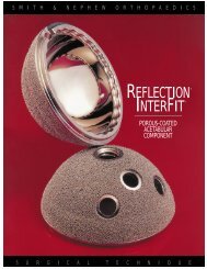
Preoperative Planning<br />
Both an anteroposterior radiograph of the pelvis<br />
with the hips in neutral rotation and a lateral hip<br />
radiograph optimize preoperative templating.<br />
The proximal one-third of the femur should be<br />
visible on these radiographs.<br />
Figure 1<br />
Anteroposterior<br />
radiograph<br />
demonstrating<br />
1 method of<br />
determining leg<br />
length inequality<br />
Reference points should be placed at the center<br />
of the femoral head and at the junction of the<br />
femoral neck and proximal border of the lesser<br />
trochanter on the anteroposterior radiograph.<br />
This should be done on both the operative and<br />
nonoperative sides. The distance between the<br />
center of the femoral head and the point at the<br />
top of the lesser trochanter should be measured<br />
with the ruler on the X-ray template.<br />
This should be done on both the operative and<br />
nonoperative sides as shown in Figure 1. If there<br />
is a significant discrepancy, a straight line can<br />
be drawn across the inferior margins of the<br />
obturator foramina to determine where the line<br />
intersects both femora. The surgeon can then<br />
determine whether lengthening of the operative<br />
side is needed.<br />
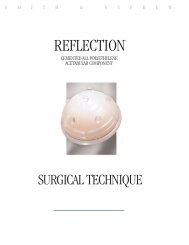
Figure 2<br />
Anteroposterior<br />
radiograph<br />
demonstrating<br />
proper templating<br />
of a femur<br />
NOTE: Evidence of a leg length discrepancy<br />
should be corroborated by a preoperative<br />
physical examination.<br />
The appropriate size stem should be chosen<br />
based upon the size of the femoral canal and<br />
the desired cement mantle. The cement mantle<br />
outlined on the X-ray template should reach the<br />
endosteal surface over the mid-portion of the<br />
stem as shown in Figure 2. A through-the-groin<br />
lateral X-ray can be used to more accurately<br />
determine proper stem sizing.<br />
4
On the anteroposterior film, the center of<br />
rotation of the prosthetic femoral head should<br />
overlay the center of rotation of the patient’s<br />
femoral head. In cases of significant distortion<br />
on the operative side, the non-operative side<br />
may be used. With the stem centered in the<br />
canal and the prosthetic center of rotation<br />
aligned with the patient’s center of rotation,<br />
the neck cut can be marked through the slot<br />
in the template. The distance between this<br />
mark for the neck cut and the mark on the<br />
lesser trochanter should be recorded. This<br />
number will aid in making the femoral neck<br />
resection at the appropriate level.<br />
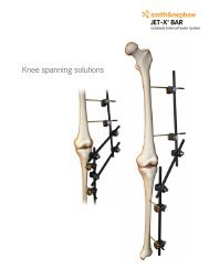
Figure 3<br />
Anteroposterior<br />
radiograph of a<br />
properly implanted<br />
SYNERGY Cemented<br />
Stem<br />
With the X-ray template in proper alignment,<br />
the femoral head neck length and stem offset<br />
should be recorded. Using this methodology<br />
helps to optimize both the leg length and offset<br />
of the proximal femur.<br />
A properly implanted SYNERGY Cemented Stem<br />
that provides both normal leg length and offset<br />
is shown in Figure 3.<br />
5
SYNERGY Cemented Stem<br />
Stem Specifications<br />
For use with Smith & Nephew 12/14 femoral heads only<br />
Stem Stem Minimum Cross A-P M-L<br />
Size Length Centralizer Section Width Width<br />
Size<br />
9 110mm 8mm 8mm 11mm 24mm<br />
10 115mm 8mm 8mm 12mm 25mm<br />
11 120mm 9mm 9mm 13mm 26mm<br />
12 125mm 10mm 10mm 14mm 27mm<br />
13 130mm 10mm 11mm 15mm 28mm<br />
14 135mm 11mm 12mm 16mm 29mm<br />
15 140mm 12mm 13mm 17mm 30mm<br />
16 140mm 12mm 14mm 18mm 31mm<br />
17 140mm 13mm 15mm 19mm 32mm<br />
Neck Height mm<br />
When Femoral Head Component Selected Is:<br />
Size -3 +0 +4 +8 +12 +16<br />
9 25 27 29 32 35 37<br />
10 26 27 30 33 35 38<br />
11 26 28 31 33 36 39<br />
12 27 29 31 34 37 39<br />
13 28 30 32 35 38 40<br />
14 28 30 33 35 38 41<br />
15 29 30 33 36 38 41<br />
16 29 31 34 37 39 42<br />
17 30 32 35 38 40 43<br />
Neck Offset mm<br />
When Femoral Head Component Selected Is:<br />
Size -3 +0 +4 +8 +12 +16<br />
9 32 34 37 40 43 46<br />
9 HO 38 40 43 46 49 52<br />
10 33 35 38 41 44 47<br />
10 HO 39 41 44 47 50 53<br />
11 34 36 39 42 45 48<br />
11 HO 40 42 45 48 51 54<br />
12 34 37 40 43 46 49<br />
12 HO 40 43 46 49 52 55<br />
13 35 37 40 43 46 49<br />
13 HO 41 43 46 49 52 55<br />
14 36 38 41 44 47 50<br />
14 HO 44 46 49 52 55 58<br />
15 37 39 42 45 48 51<br />
15 HO 45 47 50 53 56 59<br />
16 37 40 43 46 49 52<br />
16 HO 45 48 51 54 57 60<br />
17 38 40 43 46 49 52<br />
17 HO 46 48 51 54 57 60<br />
Neck Length mm<br />
When Femoral Head Component Selected Is:<br />
Size -3 +0 +4 +8 +12 +16<br />
9 28 31 35 39 43 47<br />
9 HO 32 35 39 43 47 51<br />
10 29 32 36 40 44 48<br />
10 HO 33 36 40 44 48 52<br />
11 29 32 36 40 44 48<br />
11 HO 33 36 40 44 48 52<br />
12 30 33 37 41 45 49<br />
12 HO 34 37 41 45 49 53<br />
13 31 34 38 42 46 50<br />
13 HO 35 38 42 46 50 54<br />
14 32 34 38 42 46 50<br />
14 HO 37 40 44 48 52 56<br />
15 32 35 39 43 47 51<br />
15 HO 37 40 44 48 52 56<br />
16 33 36 40 44 48 52<br />
16 HO 38 41 45 49 53 57<br />
17 34 37 41 45 49 53<br />
17 HO 39 42 46 50 54 58<br />
6
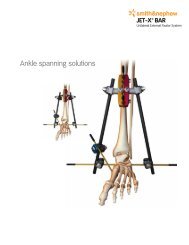
Not Actual Size<br />
A-P WIDTH<br />
HIGH OFFSET<br />
NECK HEIGHT<br />
STANDARD OFFSET<br />
M-L WIDTH<br />
NECK LENGTH<br />
+16*<br />
+12*<br />
+8<br />
+4<br />
+0<br />
–3<br />
For use with Smith & Nephew<br />
12/14 femoral heads only.<br />
0<br />
-3 femoral heads available<br />
in 28, 32 and 36mm only.<br />
+16 femoral heads available<br />
in 28 and 32mm only.<br />
* Denotes skirted heads<br />
(except 36mm)<br />
30<br />
20<br />
10<br />
2-3mm<br />
CEMENT<br />
MANTLE<br />
NECK ANGLE<br />
131 O<br />
Neck Length<br />
Standard Offset<br />
High Offset<br />
CEMENT<br />
MANTLE<br />
(1mm)<br />
CROSS<br />
SECTION<br />
STEM LENGTH<br />
DISTAL<br />
CENTRALIZER<br />
NOTE: For illustration purposes only.<br />
Surgical templates are available by<br />
contacting your Smith & Nephew<br />
representative or Customer Service.<br />
7
SYNERGY Cemented Stem<br />
Surgical Technique<br />
Femoral Osteotomy<br />
The point of the femoral neck resection should be<br />
marked with electrocautery corresponding to both<br />
the preoperative templating and the intraoperative<br />
measurement. Prior to the resection of the femoral<br />
head, assemble the broach, trial neck and trial<br />
femoral head corresponding to the implant that<br />
was templated. Place this trial stem on the femur<br />
to verify that the center of the prosthetic head<br />
aligns with the center of the femoral head. This<br />
will confirm that the level of the femoral neck<br />
resection is appropriate and will re-establish<br />
the desired leg length and offset of the proximal<br />
femur. Osteotomize the femoral neck.<br />
Open Femoral Canal<br />
Remove remnants of the femoral neck and open<br />
the medullary canal using the box osteotome.<br />
Prepare Acetabulum<br />
If acetabular reconstruction is required, prepare<br />
the acetabulum using the surgical technique for<br />
the intended acetabular <strong>com</strong>ponent.<br />
8
Femoral Canal Preparation<br />
Use the canal finder and modular T-handle<br />
for initial femoral reaming.<br />
NOTE: It is important to stay lateral with both<br />
the box osteotome and canal finder. Care<br />
should be taken to ensure that the initial<br />
reaming tract into the femur is in neutral<br />
alignment with the femoral axis.<br />
Femoral Reaming<br />
Continue to enlarge the femoral canal<br />
sequentially using the femoral reamers.<br />
Each reamer is marked with 2 or 3 lines.<br />
Stop reaming when the mark on the reamer<br />
associated with the templated stem size is<br />
even with the medial femoral neck resection<br />
or endosteal bone resistance is encountered.<br />
If reaming be<strong>com</strong>es difficult before reaching<br />
the templated stem size, consider using a stem<br />
size smaller than the templated stem size.<br />
NOTE: It is important to stay lateral with the<br />
femoral reamers to ensure that the canal is<br />
being opened in neutral alignment with the<br />
femoral axis.<br />
OPTIONAL: If utilizing fully toothed broaches,<br />
a broach-only technique can be performed.<br />
9
SYNERGY Cemented Stem<br />
Broach Assembly/Disassembly<br />
Assemble the broach to the broach handle by<br />
placing the broach post in the clamp. Use the<br />
thumb to lock the clamp onto the broach. A<br />
modular anteversion handle can be assembled<br />
to the broach handle to provide version control.<br />
Disassemble the broach from the broach handle<br />
by placing 2 fingers (index and middle) in the<br />
rectangular slot. Apply pressure to the release<br />
bar by squeezing the 2 fingers toward the thumb<br />
resting on the medial side of the broach<br />
handle frame.<br />
Femoral Broaching<br />
Start the broaching procedure along the axis<br />
of the femur with a broach at least 2 sizes<br />
smaller than the last reamer used. Sequential<br />
broaching should then be carried out to the<br />
templated stem size. Stop broaching when the<br />
top of the last broach is slightly below the level<br />
of the resected femoral neck to facilitate<br />
calcar reaming.<br />
NOTE: Care should be taken not to force<br />
a broach that is too large into the femur.<br />
Consideration should be given to using a<br />
stem size smaller than the size templated.<br />
This helps avoid intraoperative fractures<br />
of the femur.<br />
The SYNERGY Broach is designed to provide a<br />
minimum 1mm cement mantle per side and a<br />
2–3mm cement mantle in the medial curve of<br />
the stem. Additional cement mantle thickness<br />
is achieved by pressuring the cement into<br />
cancellous bone.<br />
10
Calcar Preparation<br />
With the final broach fully seated, remove<br />
the broach handle. Place the calcar reamer<br />
over the post of the broach and machine the<br />
femoral neck for optimal implant collar/femoral<br />
neck contact.<br />
Trial Reduction<br />
Place the standard or high offset trial neck (as<br />
determined by templating) onto the broach post.<br />
Select the trial femoral head of desired diameter<br />
and neck length. Measure the distance between<br />
the mark at the lesser trochanter and the center<br />
of the trial femoral head. This number should<br />
correspond to the preoperative and intraoperative<br />
measurements. Adjustments in neck length<br />
and/or offset can be made at this time.<br />
If trialing for a unipolar or bipolar, trial according to<br />
the appropriate technique for the selected device.<br />
Femoral Head and Neck Length Options<br />
Trial<br />
Color 22mm 26mm 28mm 32mm 36mm<br />
Green — — -3 -3 -3<br />
Yellow +0 +0 +0 +0 +0<br />
Red +4 +4 +4 +4 +4<br />
White +8 +8 +8 +8 +8<br />
Blue +12* +12* +12* +12* +12<br />
Black — — +16* +16* —<br />
* Denotes skirted heads<br />
11
SYNERGY Cemented Stem<br />
Trial Reduction<br />
Reduce the hip and evaluate in the<br />
following ways:<br />
Soft tissue tension<br />
Some shuck is normal when applying a<br />
longitudinal distraction force to the hip. Shuck<br />
should not be excessive, and the hip should<br />
not dislocate.<br />
Anterior stability<br />
Place the leg in full adduction, full extension<br />
and hyperextension, while exerting an external<br />
rotation force. If the hip cannot be fully extended,<br />
it may be too tight. If it dislocates easily, it is too<br />
loose and impingement must be addressed or<br />
<strong>com</strong>ponent malposition exists.<br />
Posterior stability<br />
Place the leg in neutral adduction and 90°<br />
flexion. Gradually rotate internally. If it dislocates<br />
with minimal internal rotation, it is too loose and<br />
impingement must be addressed or <strong>com</strong>ponent<br />
malposition exists.<br />
Sleep position<br />
Place the leg in the “sleep position” with<br />
the operated leg semiflexed, adducted and<br />
internally rotated over the other leg. Apply<br />
axial force to try to dislocate. This position<br />
represents a dangerously unstable position<br />
that may be adopted by a patient sleeping<br />
on their nonoperated side.<br />
12
Stem<br />
Size<br />
Re<strong>com</strong>mended Cement<br />
Restrictor Depth<br />
Stem<br />
Size<br />
Minimum Centralizer<br />
Size<br />
9 130<br />
10 135<br />
11 140<br />
12 145<br />
13 150<br />
14 155<br />
15 160<br />
16 160<br />
17 160<br />
Placing the BUCK Cement Restrictor<br />
Dislocate the hip and remove all trial <strong>com</strong>ponents.<br />
The proximal flange of the cement restrictor should<br />
always be larger than the distal canal diameter.<br />
Screw the cement restrictor onto the inserter<br />
using a clockwise motion. Insert the device to<br />
the level of the medullary canal that has been<br />
predetermined (usually 1.5–2cm below the end<br />
of the stem). A re<strong>com</strong>mended cement restrictor<br />
depth is provided in the table above. Once this<br />
level is reached, disengage the restrictor from<br />
the inserter using a counterclockwise twisting<br />
motion. Remove the inserter from the medullary<br />
canal. If it is necessary to remove the restrictor<br />
prior to cement insertion, it can be reattached<br />
to the inserter rod and pulled out of the canal.<br />
9 8<br />
10 8<br />
11 9<br />
12 10<br />
13 10<br />
14 11<br />
15 12<br />
16 12<br />
17 13<br />
Selecting the Stem and Distal Centralizer<br />
Select the implant that corresponds to the last<br />
reamer and broach used. An optional distal<br />
centralizer may be placed on the stem to assist<br />
in obtaining neutral alignment of the stem and<br />
a predictable cement mantle. Each implant has<br />
a minimum distal centralizer.<br />
NOTE: All of the femoral stems will accept any<br />
of the available distal centralizers to address<br />
variations in distal femoral geometries.<br />
Using clean gloves, place the post of the<br />
selected centralizer into the hole at the distal<br />
end of the stem and push the post of the<br />
centralizer superiorly until snug.<br />
NOTE: If a distal centralizer is not used, place<br />
the distal hole plug, which is packaged with<br />
the implant, into the centralizer hole prior to<br />
inserting the stem.<br />
13
SYNERGY Cemented Stem<br />
Preparing the Femoral Canal<br />
Use a curette to remove any grossly loose<br />
cancellous bone. Irrigate the canal and pulsatile<br />
lavage to remove all debris. Continue preparing<br />
the femur with a femoral canal brush to remove<br />
any weak, cancellous bone, blood clots and<br />
marrow fats. Repeat lavaging as necessary to<br />
remove all remaining debris.<br />
Drying the Femoral Canal<br />
Connect OR suction to the femoral suction<br />
absorber handle. While mixing the cement,<br />
insert the femoral absorber into the femoral<br />
canal to dry the canal.<br />
14
Loading Cement<br />
Load VERSABOND Bone Cement into the<br />
VORTEX Vacuum Mixer.<br />
Mixing<br />
Mix the cement according to manufacturer’s<br />
instructions. Turn handle clockwise to achieve<br />
optimal homogenous mixture.<br />
15
SYNERGY Cemented Stem<br />
Injecting Cement<br />
Remove the femoral canal suction absorber and<br />
use pulsatile lavage and dry. The cement should<br />
be introduced promptly to minimize bleeding<br />
into the canal. Insert the nozzle of the cement<br />
gun to the top of the BUCK Cement Restrictor<br />
and inject cement into the canal in retrograde<br />
fashion. Continue injecting cement until the<br />
canal is <strong>com</strong>pletely full and the distal tip of the<br />
nozzle is clear of the canal.<br />
Pressurizing Cement<br />
Break off the long nozzle and place the femoral<br />
pressurizer over the short nozzle. Apply the<br />
disposable femoral pressurizer into the mouth<br />
of the canal. This will occlude the canal and<br />
<strong>com</strong>press the cement. Maintain firm pressure<br />
until the cement is in a doughy state and can<br />
withstand displacement and will allow for<br />
proper cement interdigitation into trabecular<br />
bone. Withdraw the femoral pressurizer and<br />
remove any extruded cement around the<br />
periphery of the canal.<br />
16
Implant Insertion<br />
While verifying proper alignment, insert the<br />
selected femoral stem into the canal. Fit the<br />
non-threaded, femoral stem driver into the<br />
stem driving platform and push the implant<br />
into place. Once the collar of the implant is<br />
fully seated on the calcar bone, remove excess<br />
cement. Hold the <strong>com</strong>ponent firmly until the<br />
cement has fully cured.<br />
Final Trial Reduction<br />
A final trial reduction may be performed at this<br />
time using trial femoral heads.<br />
17
SYNERGY Cemented Stem<br />
Femoral Head Assembly<br />
Clean and dry the neck taper with a clean,<br />
sterile cloth. Place the prosthetic femoral<br />
head on the neck taper and firmly impact<br />
with the femoral head impactor and a mallet<br />
several times.<br />
18
SYNERGY Cemented Stem<br />
Catalog<br />
SYNERGY Cemented Stem<br />
Forged CoCr<br />
Size Length Standard Cat. No. High Offset Cat. No.<br />
9 110mm 7131-6009 7131-6209<br />
10 115mm 7131-6010 7131-6210<br />
11 120mm 7131-6011 7131-6211<br />
12 125mm 7131-6012 7131-6212<br />
13 130mm 7131-6013 7131-6213<br />
14 135mm 7131-6014 7131-6214<br />
15 140mm 7131-6015 7131-6215<br />
16 140mm 7131-6016 7131-6216<br />
17 140mm 7131-6017 7131-6217<br />
SYNERGY Porous-Coated Stem<br />
Titanium 6Al-4V<br />
Size Length Standard Cat. No. High Offset Cat. No.<br />
8* 120mm 7130-6608 —<br />
9 135mm 7130-6609 7130-6109<br />
10 140mm 7130-6610 7130-6110<br />
11 145mm 7130-6611 7130-6111<br />
12 150mm 7130-6612 7130-6112<br />
13 155mm 7130-6613 7130-6113<br />
14 160mm 7130-6614 7130-6114<br />
15 165mm 7130-6615 7130-6115<br />
16 170mm 7130-6616 7130-6116<br />
17 175mm 7130-6617 7130-6117<br />
18 180mm 7130-6618 7130-6118<br />
19* 185mm 7192-6107 —<br />
20* 190mm 7192-6108 —<br />
* Available by special request<br />
19
SYNERGY Femoral Stem<br />
Catalog<br />
SYNERGY HA-Coated Stem<br />
Titanium 6Al-4V<br />
Size Length Standard Cat. No. High Offset Cat. No.<br />
9 135mm 7130-6709 7130-6409<br />
10 140mm 7130-6710 7130-6410<br />
11 145mm 7130-6711 7130-6411<br />
12 150mm 7130-6712 7130-6412<br />
13 155mm 7130-6713 7130-6413<br />
14 160mm 7130-6714 7130-6414<br />
15 165mm 7130-6715 7130-6415<br />
16 170mm 7130-6716 7130-6416<br />
17 175mm 7130-6717 7130-6417<br />
18 180mm 7130-6718 7130-6418<br />
SYNERGY Porous Plus HA<br />
Size Length Standard Cat. No. High Offset Cat. No.<br />
9 135mm 7130-9009 7130-9109<br />
10 140mm 7130-9010 7130-9110<br />
11 145mm 7130-9011 7130-9111<br />
12 150mm 7130-9012 7130-9112<br />
13 155mm 7130-9013 7130-9113<br />
14 160mm 7130-9014 7130-9114<br />
15 165mm 7130-9015 7130-9115<br />
16 170mm 7130-9016 7130-9116<br />
17 175mm 7130-9017 7130-9117<br />
18 180mm 7130-9018 7130-9118<br />
CONQUEST FX Stem<br />
CoCr<br />
SYNERGY Ti-Press Fit Stem<br />
Titanium<br />
Size Length Standard Cat. No.<br />
Size<br />
Standard Cat. No.<br />
9 125mm 7131-6509<br />
10 130mm 7131-6510<br />
11 135mm 7131-6511<br />
12 140mm 7131-6512<br />
13 145mm 7131-6513<br />
14 150mm 7131-6514<br />
15 150mm 7131-6515<br />
16 150mm 7131-6516<br />
17 150mm 7131-6517<br />
18 150mm 7131-6518<br />
9 7130-6809<br />
10 7130-6810<br />
11 7130-6811<br />
12 7130-6812<br />
13 7130-6813<br />
14 7130-6814<br />
15 7130-6815<br />
16 7130-6816<br />
17 7130-6817<br />
18 7130-6818<br />
20
OXINIUM Femoral Head 12/14 Taper<br />
Neck Length 28mm 32mm 36mm<br />
-3 7134-2803 7134-3203 7134-3603<br />
+0 7134-2800 7134-3200 7134-3600<br />
+4 7134-2804 7134-3204 7134-3604<br />
+8 7134-2808 7134-3208 7134-3608<br />
+12 7134-2812 7134-3212 7134-3612<br />
+16 7134-2816 7134-3216 —<br />
CoCr Femoral Head 12/14 Taper<br />
Cobalt Chromium – ASTM F 799<br />
Neck Length 22mm 26mm 28mm 32mm<br />
-3 — — 7130-2803 7130-3203<br />
+0 7130-2200 7130-2600 7130-2800 7130-3200<br />
+4 7130-2204 7130-2604 7130-2804 7130-3204<br />
+8 7130-2208 7130-2608 7130-2808 7130-3208<br />
+12 7130-2212 7130-2612 7130-2812 7130-3212<br />
+16 — — 7130-2816 7130-3216<br />
Trial Femoral Head 12/14 Taper<br />
Neck Length Color Code 22mm 26mm 28mm 32mm<br />
-3 Green — — 7135-2803 7135-3203<br />
+0 Yellow 7135-2200 7135-2600 7135-2800 7135-3200<br />
+4 Red 7135-2204 7135-2604 7135-2804 7135-3204<br />
+8 White 7135-2208 7135-2608 7135-2808 7135-3208<br />
+12 Blue 7135-2212 7135-2612 7135-2812 7135-3212<br />
+16 Black — — 7135-2816 7135-3216<br />
21
SYNERGY Hip System<br />
Catalog<br />
Femoral Instrumentation Tray No. 1<br />
Cat. No. 7136-6201<br />
Osteotomy Guide<br />
Cat. No. 7136-4000<br />
Box Osteotome<br />
Size Cat. No.<br />
Small 7136-4002<br />
Large 7136-4003<br />
Canal Finder<br />
Cat. No. 7136-4001<br />
T-Handle<br />
Cat. No. 7136-4006<br />
Tapered Reamer<br />
Size Cat. No.<br />
8-9-10 7136-6209<br />
11-12 7136-6211<br />
13-14 7136-6213<br />
15-16 7136-6215<br />
17-18 7136-6217<br />
Broach Handle<br />
(2 Per Set)<br />
Cat. No. 7136-4007<br />
Anteversion Handle<br />
Cat. No. 7136-4012<br />
22
Femoral Instrumentation Tray No. 2<br />
Cat. No. 7136-6203<br />
Fully Toothed Broach<br />
Size Cat. No.<br />
8 7136-6708<br />
9 7136-6709<br />
10 7136-6710<br />
11 7136-6711<br />
12 7136-6712<br />
13 7136-6713<br />
Size Cat. No.<br />
14 7136-6714<br />
15 7136-6715<br />
16 7136-6716<br />
17 7136-6717<br />
18 7136-6718<br />
Stem Inserter Frame<br />
Cat. No. 7136-4008<br />
Stem Inserter Pommel<br />
Cat. No. 7136-4011<br />
Trial Neck<br />
Size Standard Cat. No. High Offset Cat. No.<br />
8-13 7136-6408 7136-6508<br />
14-18 7136-6414 7136-6514<br />
Calcar Reamer<br />
Size Cat. No.<br />
Small 7136-4004<br />
Large 7136-4005<br />
Femoral Head Impactor<br />
Cat. No. 7136-4009<br />
Slap Hammer Weight<br />
Cat. No. 7136-4010<br />
23
SYNERGY Hip System<br />
Catalog<br />
Trial Femoral Head 12/14 Taper<br />
Neck Color 22mm 26mm 28mm 32mm 36mm<br />
Length Code Optional Optional Optional Optional<br />
-3 Green ––– ––– 7135-2803 7135-3203 7134-3603<br />
+0 Yellow 7135-2200 7135-2600 7135-2800 7135-3200 7134-3600<br />
+4 Red 7135-2204 7135-2604 7135-2804 7135-3204 7134-3604<br />
+8 White 7135-2208 7135-2608 7135-2808 7135-3208 7134-3608<br />
+12 Blue 7135-2212 7135-2612 7135-2812 7135-3212 7134-3612<br />
+16 Black ––– ––– 7135-2816 7135-3216 –––<br />
Optional SYNERGY Instrumentation<br />
Collared Trial Neck Sterilization Tray<br />
Cat. No. 7136-6204<br />
Collared Trial Neck, Standard<br />
Size Cat. No.<br />
8-9 7136-6908<br />
10-11 7136-6910<br />
12-13 7136-6912<br />
14-15 7136-6914<br />
16-17 7136-6916<br />
Collared Trial Neck, High Offset<br />
Size Cat. No.<br />
8-9 7136-6918<br />
10-11 7136-6920<br />
12-13 7136-6922<br />
14-15 7136-6924<br />
16-17 7136-6926<br />
Cemented Stem Inserter<br />
Cat. No. 7136-4014<br />
24
VERSABOND Cement and Accessories<br />
Catalog<br />
VERSABOND Bone Cement<br />
Cat. No. 7127-1140<br />
PREP-IM Femoral Preparation Kit<br />
Cat. No. 12-1010 Includes the following:<br />
2 BUCK Cement Restrictors<br />
1 Femoral Canal Brush<br />
1 BUCK Disposable Inserter<br />
1 Femoral Canal Suction Absorber<br />
2 Concise Cement Sculps<br />
1 Medium Femoral Pressurizer<br />
Femoral Canal Brush<br />
O.D. Cat. No.<br />
19mm 11-0003<br />
12.5mm 11-0033<br />
BUCK Cement Restrictor<br />
Size Cat. No.<br />
13mm 91-4535<br />
18.5mm 12-9418<br />
25mm 12-9419<br />
30mm 7127-9420<br />
35mm 7127-9421<br />
Vent Opening Tool<br />
Cat. No. 11-0028<br />
Concise Cement Sculps Kit<br />
Cat. No. 11-1000<br />
(1 of each)<br />
25
VERSABOND Cement and Accessories<br />
Catalog<br />
Femoral Pressurizer<br />
Size Cat. No.<br />
Small 7127-0026<br />
Medium 7127-0027<br />
Large 7127-0028<br />
Femoral Canal Suction Absorber<br />
Size Cat. No.<br />
19mm 11-0037<br />
25mm 11-0038<br />
BUCK Femoral Cement Restrictor Inserter<br />
Cat. No. 11-2428<br />
Disposable Femoral Cement Compressor Cap<br />
Cat. No. 11-1435<br />
MIXOR Vacuum Mixing System with Syringe<br />
Cat. No. 7127-0020<br />
VORTEX Vacuum Mixer<br />
Cat. No. 7127-0070<br />
VORTEX Vacuum Mixer Sample<br />
Cat. No. 7127-0069<br />
Femoral Cement Compressor<br />
Cat. No. 11-1434<br />
26
VORTEX Nozzles<br />
Cat. No. Description<br />
7127-0080 Standard Breakaway<br />
7127-0081 Long Tapered<br />
7127-0084 Revision<br />
7127-0085 Umbrella<br />
7127-0071 Re-use Kit (not shown)<br />
7127-0072 Adaptor<br />
7127-0082 Angled Nozzle<br />
Connector, Schraeder<br />
Cat. No. 7127-0050<br />
Connector, Drager<br />
Cat. No. 7127-0051<br />
Connector, D.I.S.S.<br />
Cat. No. 7127-0052<br />
Stryker Foot Pump Adapter<br />
Cat. No. 7127-0060<br />
POWERPULSE Handpiece with Zimmer Coupling<br />
Cat. No. 7127-7000<br />
POWERPULSE Powerhose with Zimmer Coupling<br />
Cat. No. 7127-7001<br />
27
VERSABOND Cement and Accessories<br />
Catalog<br />
POWERPULSE Hip with Suction<br />
Cat. No. 7127-7004<br />
POWERPULSE Hip without Suction<br />
Cat. No. 7127-7005<br />
Knee with Suction<br />
Cat. No. 7127-7002<br />
Knee without Suction<br />
Cat. No. 7127-7003<br />
MIXOR Hose Only<br />
(not shown)<br />
Cat. No. 7127-0041<br />
MIXOR Pump Only<br />
(not shown)<br />
Cat. No. 7127-0042<br />
InjectOR Gun<br />
Cat. No. 7127-2000<br />
28
Important Medical Information<br />
Warnings and Precautions<br />
Total Hip System<br />
Important Note<br />
Total hip replacement (THR) arthroplasty has be<strong>com</strong>e a successful procedure<br />
for relieving pain and restoring motion in patients who are disabled from hip<br />
arthropathy. The goals of total hip replacement are to decrease pain, increase<br />
function, and increase mobility.<br />
Materials<br />
Femoral <strong>com</strong>ponents are cobalt chromium alloy, titanium 6Al-4V alloy or<br />
stainless steel. Femoral heads are cobalt chromium alloy, zirconia ceramic,<br />
alumina ceramic, OXINIUM oxidized zirconium or stainless steel. Acetabular<br />
liners are ultra-high molecular weight polyethylene or alumina ceramic. All<br />
poly acetabular <strong>com</strong>ponents are ultra-high molecular weight polyethylene.<br />
Acetabular shells are titanium 6Al-4V alloy. The <strong>com</strong>ponent material is provided<br />
on the outside carton label.<br />
Note: Ceramic/ceramic implants are not available in the U.S.A.<br />
Some of the alloys needed to produce orthopedic implants contain some<br />
metallic <strong>com</strong>ponents that may be carcinogenic in tissue cultures or intact<br />
organism under very unique circumstances. Questions have been raised in<br />
the scientific literature as to whether or not these alloys may be carcinogenic<br />
in implant recipients. Studies conducted to evaluate this issue have not identified<br />
conclusive evidence of such phenomenon, in spite of the millions of<br />
implants in use.<br />
Description of System<br />
The Total Hip System consists of femoral <strong>com</strong>ponents, proximal pads, taper<br />
sleeves, distal sleeves, acetabular <strong>com</strong>ponents, fixation screws and pegs,<br />
hole covers, centralizers, and femoral heads. Components may be grit blasted,<br />
porous coated, hydroxylapatite (HA) coated, or HA porous coated. All<br />
implantable devices are designed for single use only.<br />
Femoral Components<br />
Femoral <strong>com</strong>ponents are available in a variety of sizes. Porous coated <strong>com</strong>ponents<br />
are coated for biological ingrowth. Proximally and distally modular<br />
femoral <strong>com</strong>ponents accept proximal pads and distal sleeves, respectively.<br />
Non-porous femoral <strong>com</strong>ponents can feature PMMA centralizers that help<br />
produce a uniform thickness of cement.<br />
Femoral <strong>com</strong>ponents are available with a Small (10/12), Large (14/16), or 12/14<br />
global taper.<br />
Small taper femoral <strong>com</strong>ponents mate and lock directly with a 22mm metal,<br />
oxidized zirconium or ceramic head. The Small taper also mates with a taper<br />
sleeve which, in turn, mates with either metal or ceramic heads (26, 28, or<br />
32mm), bipolar or unipolar <strong>com</strong>ponents.<br />
Large taper femoral <strong>com</strong>ponents mate and lock with either metal heads (26,<br />
28, or 32mm), ceramic heads (28 or 32mm), oxidized zirconium (28, 32, or<br />
36mm), bipolars or unipolar <strong>com</strong>ponents.<br />
Femoral <strong>com</strong>ponents with a 12/14 taper mate and lock with either metal<br />
heads, oxidized zirconium heads, ceramic heads, bipolar or unipolar <strong>com</strong>ponents.<br />
Small, Large, and 12/14 taper femoral <strong>com</strong>ponent tapers are machined to<br />
mate and lock with ceramic heads, thus preventing rotation of the ceramic<br />
head on the stem, which would cause wear of the stem taper.<br />
Taper Sleeves<br />
A taper sleeve is required to be impacted on the Small taper femoral <strong>com</strong>ponent<br />
prior to impacting a Large (14/16) taper femoral head size 26, 28, or<br />
32mm. A taper sleeve is required to attach a unipolar head. Unipolar taper<br />
sleeves are available in Small, Large, and 12/14 tapers. Never place more than<br />
one taper sleeve on a femoral <strong>com</strong>ponent.<br />
Femoral Heads<br />
Cobalt chromium, stainless steel, oxidized zirconium, and ceramic heads are<br />
available in multiple neck lengths for proper anatomic and musculature fit.<br />
Heads are highly polished for reduced friction and wear. The following zirconia<br />
ceramic heads are available for use only with Small and Large taper<br />
femoral <strong>com</strong>ponents:<br />
Zirconia Head Neck Length<br />
Ceramic Diameter<br />
42-7815 32mm Standard 0mm<br />
42-7816 32mm Long + 4mm<br />
42-7817 32mm X-Long + 8mm<br />
42-7818 28mm Standard 0mm<br />
42-7819 28mm Long + 4mm<br />
42-7820 28mm X-Long + 8mm<br />
Note: 32mm heads with a -3mm neck length are not available for use with<br />
the Small taper stems.<br />
In addition to the <strong>com</strong>ponents listed above, the following <strong>com</strong>ponents are<br />
available for use only with Small taper femoral <strong>com</strong>ponents:<br />
Zirconia Head Neck Length<br />
Ceramic Diameter<br />
7132-0002 22mm Long + 4mm<br />
7132-0006 22mm X-Long + 8mm<br />
Note: 22mm Zirconia Ceramic Heads used with Small taper femoral <strong>com</strong>ponents<br />
are not available in the U.S.A.<br />
The following zirconia ceramic heads are available for use only with 12/14<br />
taper femoral <strong>com</strong>ponents:<br />
Zirconia Head Neck Length<br />
Ceramic Diameter<br />
7132-0028 28mm Standard 0mm<br />
7132-0428 28mm Long + 4mm<br />
7132-0828 28mm X-Long + 8mm<br />
7132-0026 26mm Standard 0mm<br />
7132-0426 26mm Long + 4mm<br />
7132-0826 26mm X-Long + 8mm<br />
7132-0422 22mm Long + 4mm<br />
7132-0822 22mm X-Long + 8mm<br />
The following alumina ceramic heads are available for use only with 12/14<br />
taper femoral <strong>com</strong>ponents:<br />
Alumina Head Neck Length<br />
Ceramic Diameter<br />
7133-2800 28mm Standard 0mm<br />
7133-2804 28mm Long + 4mm<br />
7133-2808 28mm X-Long + 8mm<br />
7133-3200 32mm Standard 0mm<br />
7133-3204 32mm Long + 4mm<br />
7133-3208 32mm X-Long + 8mm<br />
7133-3600 36mm Standard 0mm<br />
7133-3604 36mm Long + 4mm<br />
7133-3608 36mm X-Long + 8mm<br />
Acetabular Components<br />
Acetabular <strong>com</strong>ponents can be one piece all polyethylene, two-piece <strong>com</strong>ponent<br />
consisting of a titanium shell and a polyethylene liner or a titanium<br />
shell and an alumina ceramic liner. Please see Warnings and Precautions for<br />
specific information on screws, pegs and hole covers use. Acetabular reinforcement<br />
and reconstruction rings are used with an all polyethylene acetabular<br />
<strong>com</strong>ponent. Note: The metal shell and ceramic liner in the<br />
Ceramic/Ceramic Acetabular System are not available in the U.S.A.<br />
The BIRMINGHAM HIP Resurfacing (BHR) prosthesis is a metal-on-metal<br />
bearing <strong>com</strong>ponent consisting of a stemmed femoral head resurfacing <strong>com</strong>ponent<br />
designed for cemented insertion and a hemispherical acetabular cup<br />
designed for cementless interference fit into the acetabulum. The acetabular<br />
cup has hydroxylapatite coating applied to the external surface and porous<br />
coating. Cement should not be used with this type of implant. Note: The BHR<br />
prosthesis is not available in the U.S.A.<br />
Note: 10 Mrad cross-linked polyethylene (UHMWPE) REFLECTION Acetabular<br />
Liners may be used with metal (CoCr), oxidized zirconium, alumina ceramic or<br />
zirconia ceramic femoral heads.<br />
Femoral <strong>com</strong>ponents and femoral heads are designed for use with any Smith<br />
& Nephew polyethylene acetabular <strong>com</strong>ponent or polyethylene-lined, metalbacked<br />
acetabular <strong>com</strong>ponent having an appropriately-sized inside diameter.<br />
INDICATIONS, CONTRAINDICATIONS, AND ADVERSE EFFECTS<br />
Hip <strong>com</strong>ponents are indicated for individuals undergoing primary and revision<br />
surgery where other treatments or devices have failed in rehabilitating<br />
hips damaged as a result of trauma or noninflammatory degenerative joint<br />
disease (NIDJD) or any of its <strong>com</strong>posite diagnoses of osteoarthritis, avascular<br />
necrosis, traumatic arthritis, slipped capital epiphysis, fused hip, fracture<br />
of the pelvis, and diastrophic variant.<br />
Hip <strong>com</strong>ponents are also indicated for inflammatory degenerative joint disease<br />
including rheumatoid arthritis, arthritis secondary to a variety of diseases<br />
and anomalies, and congenital dysplasia; old, remote osteomyelitis<br />
with an extended drainage-free period, in which case, the patient should be<br />
warned of an above normal danger of infection postoperatively; treatments of<br />
nonunion, femoral neck fracture and trochanteric fractures of the proximal<br />
femur with head involvement that are unmanageable using other techniques;<br />
endoprosthesis, femoral osteotomy, or Girdlestone resection; fracture-dislocation<br />
of the hip; and correction of deformity.<br />
The BIRMINGHAM HIP Resurfacing (BHR) arthroplasty system is indicated for<br />
use for reduction or relief of pain and/or improved hip function in patients<br />
who are candidates for a total hip replacement but who have evidence of<br />
good femoral bone stock. These patients should also be skeletally mature<br />
with the following conditions: noninflammatory degenerative joint disease<br />
such as osteoarthritis, avascular necrosis, ankylosis, protrusio acetabuli, and<br />
painful hip dysplasia; inflammatory degenerative joint disease such as<br />
rheumatoid arthritis; correction of functional deformity; and are of an age<br />
such that total hip revision is likely at some future point.<br />
Acetabular reinforcement and reconstruction rings are intended to be used in<br />
primary and revision surgeries where the acetabulum has the deficiencies of<br />
the acetabular roof, anterior or posterior pillar, medial wall deficiency, and /<br />
or protrusion as a result of the indications listed previously.<br />
Some of the diagnoses listed above and below may also increase the chance<br />
of <strong>com</strong>plications and reduce the chance of a satisfactory result.<br />
Contraindications<br />
1. Conditions that would eliminate or tend to eliminate adequate implant<br />
support or prevent the use of an appropriately-sized implant, e.g.:<br />
a. blood supply limitations;<br />
b. insufficient quantity or quality of bone support, e.g., osteoporosis, or<br />
metabolic disorders which may impair bone formation, and osteomalacia;<br />
and<br />
c. infections or other conditions which lead to increased bone resorption.<br />
2. Mental or neurological conditions which tend to impair the patient's ability<br />
or willingness to restrict activities.<br />
3. Physical conditions or activities which tend to place extreme loads on<br />
implants, e.g., Charcot joints, muscle deficiencies, multiple joint disabilities,<br />
etc.<br />
4. Skeletal immaturity.<br />
5. The zirconia ceramic head is contraindicated for use with any other product<br />
than an UHMW polyethylene cup or a metal backed UHMW polyethylene<br />
cup.<br />
6. The alumina ceramic liner is contraindicated for use with any product<br />
other than the metal shell with the correlating inner taper geometry and<br />
the appropriate sized alumina ceramic head. The alumina ceramic liner<br />
should only be used with the alumina ceramic head.<br />
Contraindications may be relative or absolute and must be carefully weighed<br />
against the patient's entire evaluation and the prognosis for possible alternative<br />
procedures such as non-operative treatment, arthrodesis, femoral<br />
osteotomy, pelvic osteotomy, resection arthroplasty, hemiarthroplasty and<br />
others. Conditions presenting increased risk of failure include: osteoporosis,<br />
metabolic disorders which may impair bone formation, and osteomalacia.<br />
Possible Adverse Effects<br />
1. Wear of the polyethylene and ceramic articulating surfaces of acetabular<br />
<strong>com</strong>ponents may occur. Higher rates of wear may be initiated by the presence<br />
of particles of cement, metal, or other debris which can develop during<br />
or as a result of the surgical procedure and cause abrasion of the articulating<br />
surfaces. Higher rates of wear may shorten the useful life of the<br />
prosthesis and lead to early revision surgery to replace the worn prosthetic<br />
<strong>com</strong>ponents.<br />
2. With all joint replacements, asymptomatic, localized, progressive bone<br />
resorption (osteolysis) may occur around the prosthetic <strong>com</strong>ponents as a<br />
consequence of foreign-body reaction to particulate wear debris. Particles<br />
are generated by interaction between <strong>com</strong>ponents, as well as between<br />
the <strong>com</strong>ponents and bone, primarily through wear mechanisms of adhesion,<br />
abrasion, and fatigue. Secondarily, particles may also be generated<br />
by third-body particles lodged in the polyethylene or ceramic articular surfaces.<br />
Osteolysis can lead to future <strong>com</strong>plications necessitating the<br />
removal or replacement of prosthetic <strong>com</strong>ponents.<br />
3. Loosening, bending, cracking, or fracture of implant <strong>com</strong>ponents may<br />
result from failure to observe the Warnings and Precautions below.<br />
Fracture of the implant can occur as a result of trauma, strenuous activity,<br />
improper alignment, or duration of service.<br />
4. Dislocations, subluxation, decreased range of motion, or lengthening or<br />
shortening of the femur caused by improper neck selection, positioning,<br />
looseness of acetabular or femoral <strong>com</strong>ponents, extraneous bone, penetration<br />
of the femoral prosthesis through the shaft of the femur, fracture of<br />
the acetabulum, intrapelvic protrusion of acetabular <strong>com</strong>ponent, femoral<br />
impingement, periarticular calcification, and/or excessive reaming.<br />
5. Fracture of the pelvis or femur: post-operative pelvic fractures are usually<br />
stress fractures. Femoral fractures are often caused by defects in the<br />
femoral cortex due to misdirected reaming, etc. Intraoperative fractures<br />
are usually associated with old congenital deformity, improper stem selection,<br />
improper broaching, and/or severe osteoporosis.<br />
6. Infection, both acute post-operative wound infection and late deep wound<br />
sepsis.<br />
7. Neuropathies; femoral, sciatic, peroneal nerve, and lateral femoral cutaneous<br />
neuropathies have been reported. Temporary or permanent nerve<br />
damage resulting in pain or numbness of the affected limb.<br />
8. Wound hematoma, thromboembolic disease including venous thrombosis,<br />
pulmonary embolus, or myocardial infarction.<br />
9. Myositis ossificans, especially in males with hypertrophic arthritis, limited<br />
pre-operative range of motion and/or previous myositis. Also, periarticular<br />
calcification with or without impediment to joint mobility can cause<br />
decreased range of motion.<br />
10. Trochanteric nonunion usually associated with early weight bearing<br />
and/or improper fixation of the trochanter, when a transtrochanteric surgical<br />
approach is used.<br />
11. Although rare, metal sensitivity reactions and/or allergic reactions to foreign<br />
materials have been reported in patients following joint replacement.<br />
12. Damage to blood vessels.<br />
13. Traumatic arthrosis of the knee from intraoperative positioning of the<br />
extremity.<br />
14. Delayed wound healing.<br />
15. Aggravated problems of the affected limb or contralateral extremity<br />
caused by leg length discrepancy, excess femoral medialization, or muscle<br />
deficiency.<br />
16. Failure of the porous coating/ substrate interface or hydroxylapatite coating/<br />
porous coating bonding may result in bead separation delamination.<br />
17. Stem migration or subsidence has occurred in conjunction with <strong>com</strong>paction<br />
grafting procedures usually resulting from insufficient graft material<br />
or improper cement techniques. Varus stem alignment may also be<br />
responsible.<br />
Warnings and Precautions<br />
The patient should be warned of surgical risks, and made aware of possible<br />
adverse effects. The patient should be warned that the device does not<br />
replace normal healthy bone, that the implant can break or be<strong>com</strong>e damaged<br />
as a result of strenuous activity or trauma, and that it has a finite expected<br />
service life and may need to be replaced in the future. Do not mix <strong>com</strong>ponents<br />
from different manufacturers. Additional Warnings and Precautions<br />
may be included in <strong>com</strong>ponent literature.<br />
29
Preoperative<br />
1. Use extreme care in handling and storage of implant <strong>com</strong>ponents.<br />
Cutting, bending, or scratching the surface of <strong>com</strong>ponents can significantly<br />
reduce the strength, fatigue resistance, and/or wear characteristics<br />
of the implant system. These, in turn, may induce internal stresses<br />
that are not obvious to the eye and may lead to fracture of the <strong>com</strong>ponent.<br />
Implants and instruments should be protected from corrosive environments<br />
such as salt air during storage. Do not allow the porous surfaces<br />
to <strong>com</strong>e in contact with cloth or other fiber-releasing materials.<br />
2. Allergies and other reactions to device materials, although infrequent,<br />
should be considered, tested for (if appropriate), and ruled out preoperatively.<br />
3. Fixation and expected longevity of <strong>com</strong>ponents expected to be left in<br />
place at revision surgery should be thoroughly assessed.<br />
4. Surgical technique information is available upon request. The surgeon<br />
should be familiar with the technique. Refer to medical or manufacturer<br />
literature for specific product information.<br />
5. Intraoperative fracture or breaking of instruments can occur. Instruments<br />
which have experienced extensive use or excessive force are susceptible<br />
to fracture. Instruments should be examined for wear, or damage,<br />
prior to surgery.<br />
6. Do not cold water quench ceramic <strong>com</strong>ponents and never sterilize<br />
ceramic heads while fixed on the stem taper. (See sterilization section,<br />
below.)<br />
7. Select <strong>com</strong>ponents such that the zirconia ceramic and oxidized zirconium<br />
heads always articulate with a UHMW polyethylene cup or a metal<br />
backed UHMW polyethylene cup and alumina heads articulate with<br />
UHMW polyethylene or alumina liners. Zirconia ceramic, oxidized zirconium,<br />
and alumina heads should never articulate against metal because<br />
severe wear of the metal will occur.<br />
8. Select only Smith & Nephew femoral <strong>com</strong>ponents that indicate their use<br />
with ceramic heads. This is important because the taper on the stem is<br />
machined to tightly mate and lock with the ceramic head thus preventing<br />
rotation of the ceramic head on the stem. Also, an improperly dimensioned<br />
taper could result in fracture of the ceramic head.<br />
9. The zirconia ceramic head is <strong>com</strong>posed of a new ceramic material with<br />
limited clinical history. Although mechanical testing demonstrates that<br />
when used with a polyethylene acetabular <strong>com</strong>ponent the yttria stabilized<br />
zirconia ball produces a relatively low amount of particulates, the<br />
total amount of particulate remains undetermined. Because of the limited<br />
clinical and preclinical experience, the biological effect of these particulates<br />
can not be predicted.<br />
10. Alumina ceramic should never articulate against metal because severe<br />
wear could occur.<br />
11. If a <strong>com</strong>puter assisted surgery system is used, consult the applicable<br />
software and hardware reference manuals provided by the manufacturer<br />
to ensure proper operation of this equipment.<br />
Intraoperative<br />
1. The general principles of patient selection and sound surgical judgment<br />
apply. The correct selection of the implant is extremely important. The<br />
appropriate type and size should be selected for patients with consideration<br />
of anatomical and biomechanical factors such as patient age and<br />
activity levels, weight, bone and muscle conditions, any prior surgery and<br />
anticipated future surgeries, etc. Generally, the largest cross-section<br />
<strong>com</strong>ponent which will allow adequate bone support to be maintained is<br />
preferred. Failure to use the optimum-sized <strong>com</strong>ponent may result in<br />
loosening, bending, cracking, or fracture of the <strong>com</strong>ponent and/or bone.<br />
2. Correct selection of the neck length and cup, and stem positioning, are<br />
important. Muscle looseness and/or malpositioning of <strong>com</strong>ponents may<br />
result in loosening, subluxation, dislocation, and/or fracture of <strong>com</strong>ponents.<br />
Increased neck length and varus positioning will increase stresses<br />
which must be borne by the stem. The <strong>com</strong>ponent should be firmly<br />
seated with the <strong>com</strong>ponent insertion instruments.<br />
3. Care should be taken not to scratch, bend (with the exception of the<br />
Reconstruction Rings) or cut implant <strong>com</strong>ponents during surgery for the<br />
reasons stated in Number One of the "Pre-Operative" section of<br />
"Warnings and Precautions."<br />
4. A +12mm or +16mm femoral head should not be used with any Small<br />
taper stems.<br />
5. Distal sleeves should not be used to bridge cortical defects that lie within<br />
25mm of the tip of the base stem.<br />
6. MATRIX Small taper stem sizes 8S - 10L must have a minimum neck<br />
length of +8mm when used with a bipolar <strong>com</strong>ponent; and Small taper<br />
stem sizes 12S - 16L must have a minimum neck length of +4mm when<br />
used with a bipolar <strong>com</strong>ponent.<br />
7. Modular heads and femoral <strong>com</strong>ponents should be from the same manufacturer<br />
to prevent mismatch of tapers.<br />
8. Stainless steel heads and stainless steel stems should only be used<br />
together. Neither should be used with other metal <strong>com</strong>ponents.<br />
9. Use only REFLECTION Liners with REFLECTION Shells.<br />
10. Clean and dry stem taper prior to impacting the femoral head or taper<br />
sleeve. The modular femoral head <strong>com</strong>ponent must be firmly seated on<br />
the femoral <strong>com</strong>ponent to prevent disassociation.<br />
11. Take care, when positioning and drilling screw and peg holes, to avoid<br />
penetration of the inner cortex of the pelvis, penetration of the sciatic<br />
notch, or damage to vital neurovascular structures. Perforation of the<br />
pelvis with screws that are too long can rupture blood vessels causing<br />
the patient to hemorrhage. Do not place a screw in the center hole of the<br />
acetabular prosthesis. Placement of drills and screws in the anterior or<br />
medial portions of the prosthesis is associated with a high risk of potentially<br />
fatal vascular injury. Bone screws must be <strong>com</strong>pletely seated in the<br />
holes of the shell to allow proper locking for the acetabular <strong>com</strong>ponent<br />
liner. If the tapered pegs need to be removed from the shell after<br />
impaction of the pegs, do not reuse the pegs or the peg shell holes. Use<br />
new pegs and different shell holes, or a new shell if necessary.<br />
12. USE ONLY REFLECTION TITANIUM SPHERICAL HEAD BONE SCREWS, UNI-<br />
VERSAL CANCELLOUS BONE SCREWS, TAPERED PEGS, AND HOLE COV-<br />
ERS with the REFLECTION Acetabular Components. REFLECTION SP3,<br />
FSO and INTERFIT Shells accept both REFLECTION spherical head<br />
screws and Universal cancellous bone screws. REFLECTION FSO and<br />
INTERFIT Shells accept the Modified REFLECTION screw hole covers. The<br />
REFLECTION V Shell only accepts Universal Cancellous, REFLECTION<br />
screws, and tapered screw-hole covers, not pegs. REFLECTION<br />
Peripheral Hole Screws should only be used with REFLECTION Peripheral<br />
Hole Shells. Locking Head Pegs and REFLECTION SP Screw Hole Covers<br />
are only for use with SP3 Shells. Tapered pegs can only be used with<br />
REFLECTION V Shells. The threaded center hole in REFLECTION Shells<br />
only accepts the threaded hole cover, not screws or pegs. The INTERFIT<br />
threaded hole cover is only for use with REFLECTION INTERFIT, SP3,<br />
Spiked and No Hole Shells. The REFLECTION threaded hole cover can be<br />
used with all REFLECTION shells. Refer to product literature for proper<br />
adjunctive fixation and hole cover usage.<br />
13. Prior to seating modular <strong>com</strong>ponents, surgical debris including tissue<br />
must be cleaned from the surfaces. Debris, including bone cement, may<br />
inhibit the <strong>com</strong>ponent locking mechanism. If the shell is to be cemented<br />
in place, remove extraneous cement with a plastic sculps tool to ensure<br />
proper locking of the liner. During liner insertion, make sure soft tissue<br />
does not interfere with the shell/liner interface. Chilling the liner reduces<br />
the impaction force required to seat the liner. Modular <strong>com</strong>ponents must<br />
be assembled securely to prevent disassociation. Debris inhibits the<br />
proper fit and locking of modular <strong>com</strong>ponents which may lead to early<br />
failure of the procedure. Failure to properly seat the acetabular liner into<br />
the shell can lead to disassociation of the liner from the shell.<br />
14. Avoid repeated assembly and disassembly of the modular <strong>com</strong>ponents<br />
which could <strong>com</strong>promise the critical locking action of the locking mechanism.<br />
15. Care is to be taken to assure <strong>com</strong>plete support of all parts of the device<br />
embedded in bone cement to prevent stress concentration which may<br />
lead to failure of the procedure. During curing of the cement, care should<br />
be taken to prevent movement of the implant <strong>com</strong>ponents.<br />
16. If the head is removed from a femoral <strong>com</strong>ponent that will be left in place<br />
at revision surgery, it is re<strong>com</strong>mended that a metal head be used. A<br />
ceramic head may fracture from irregularities on the femoral <strong>com</strong>ponent<br />
taper.<br />
17. If <strong>com</strong>ponents are to be left in place at revision surgery, they should first<br />
be thoroughly checked for signs of looseness, etc. and replaced if necessary.<br />
The head/neck <strong>com</strong>ponent should be changed only when clinically<br />
necessary.<br />
18. Once removed from the patient, implants previously implanted should<br />
never be reused, since internal stresses which are not visible may lead<br />
to early bending or fracture of these <strong>com</strong>ponents.<br />
19. With the congenitally dislocated hip, special care should be taken to prevent<br />
sciatic nerve palsy. Also, note that the femoral canal is often very<br />
small and straight and may require an extra-small straight femoral prosthesis;<br />
however, a regular-sized prosthesis should be used when possible.<br />
Note that the true acetabulum is rudimentary and shallow. A false<br />
acetabulum should not ordinarily be utilized as a cup placement site for<br />
anatomical and biomechanical reasons.<br />
20. With rheumatoid arthritis, especially for those patients on steroids, bone<br />
may be extremely osteoporotic. Care should be taken to prevent excessive<br />
penetration of the acetabular floor or fracture of the medial acetabular<br />
wall, femur, or greater trochanter.<br />
21. Revision procedures for previous arthroplasty, Girdlestone, etc., are technically<br />
demanding and difficult to exercise. Common errors include misplacement<br />
of the incision, inadequate exposure or mobilization of the<br />
femur, inadequate removal of ectopic bone, or improper positioning of<br />
<strong>com</strong>ponents. Postoperative instability as well as excessive blood loss<br />
can result. In summary, increased operative time, blood loss, increased<br />
incidence of pulmonary embolus and wound hematoma can be expected<br />
with revision procedures.<br />
22. Prior to closure, the surgical site should be thoroughly cleaned of<br />
cement, bone chips, ectopic bone, etc. Ectopic bone and/or bone spurs<br />
may lead to dislocation or painful or restricted motion. Range of motion<br />
should be thoroughly checked for early contact or instability.<br />
23. Proper positioning of the <strong>com</strong>ponents is important to minimize impingement<br />
which could lead to early failure, premature wear, and/or dislocation.<br />
24. In order to minimize the risks of dislocation and loosening of the shellacetabular<br />
bone or shell-bone cement interface that may occur when<br />
using a metallic shell intended for biological fixation or cemented use<br />
only, surgeons should consider providing immediate resistance to tensile<br />
forces between the metallic shell and the acetabular bone or bone<br />
cement interface through the use of orthopedic bone fixation devices<br />
such as bone screws, spikes, screw threads, pegs, fins, or other bone<br />
fixation devices.<br />
25. Physicians should consider <strong>com</strong>ponent malposition, <strong>com</strong>ponent placement,<br />
and the effect on range of motion when using modular heads (with<br />
sleeves or skirts) and extended liners.<br />
26. For <strong>com</strong>puter assisted surgery systems, it is extremely important to correctly<br />
select input parameters (e.g. bony landmarks). Operators of this<br />
equipment should be familiar with the anatomy relevant to the procedure.<br />
Failure to provide proper input could cause problems such as violation of<br />
critical anatomical structures and malpositioned implants.<br />
Postoperative<br />
1. Postoperative directions and warnings to patients by physicians, and<br />
patient care, are extremely important. Gradual weight bearing is begun<br />
after surgery in ordinary total hip arthroplasty. However, with trochanter<br />
osteotomy or certain <strong>com</strong>plex cases, weight-bearing status should be<br />
individualized with the non or partial weight-bearing period extended.<br />
2. Patients should be warned against unassisted activity, particularly use of<br />
toilet facilities and other activities requiring excessive motion of the hip.<br />
3. Use extreme care in patient handling. Support should be provided to the<br />
operative leg when moving the patient. While placing the patient on bedpans,<br />
changing dressings, and clothing, and similar activities, precautions<br />
should be taken to avoid placing excessive load on the operative<br />
part of the body.<br />
4. Postoperative therapy should be structured to regain muscle strength<br />
around the hip and a gradual increase of activities.<br />
5. Periodic x-rays are re<strong>com</strong>mended for close <strong>com</strong>parison with immediate<br />
postoperative conditions to detect long-term evidence of changes in<br />
position, loosening, bending and/or cracking of <strong>com</strong>ponents or bone<br />
loss. With evidence of these conditions, patients should be closely<br />
observed, the possibilities of further deterioration evaluated, and the<br />
benefits of early revision considered.<br />
6. Prophylactic antibiotics should be re<strong>com</strong>mended to the patient similar to<br />
those suggested by the American Heart Association for conditions or situations<br />
that may result in bacteremia.<br />
Packaging and Labeling<br />
Components should only be accepted if received by the hospital or surgeon<br />
with the factory packaging and labeling intact. If the sterile barrier has been<br />
broken, return the <strong>com</strong>ponent to Smith & Nephew, Inc.<br />
Sterilization/Resterilization<br />
Most implants are supplied sterile and have been packaged in protective<br />
trays. The method of sterilization is noted on the package label. All radiation<br />
sterilized <strong>com</strong>ponents have been exposed to a minimum of 25 kiloGrays of<br />
gamma radiation. If not specifically labeled sterile, the implants and instruments<br />
are supplied non-sterile and must be sterilized prior to use. Inspect<br />
packages for punctures or other damage prior to surgery.<br />
Metal Components<br />
Nonporous or non-HA coated metal <strong>com</strong>ponents and oxidized zirconium<br />
heads may be initially sterilized or resterilized, if necessary, by steam autoclaving<br />
in appropriate protective wrapping, after removal of all original packaging<br />
and labeling. Protect the devices, particularly mating surfaces, from<br />
contact with metal or other hard objects which could damage the product.<br />
The following process parameters are re<strong>com</strong>mended for these devices:<br />
• Prevacuum Cycle: 4 pulses (Maximum = 26.0 psig (2.8 bars) & Minimum<br />
= 10.0 inHg (339 millibars)) with a minimum dwell time of 4 minutes at<br />
270°F to 275°F (132°C to 135°C), followed by a 1 minute purge and at least<br />
15 minutes of vacuum drying at 10 inHg (339 millibars) minimum.<br />
• For the United Kingdom, sterilization should be carried out in accordance<br />
with HTM 2010. The re<strong>com</strong>mended prevacuum sterilization cycle is:<br />
Evacuation to 100mBar for 2-3 minutes, Negative Pressure pulsing (5):<br />
800mBar-100mBar, Positive Pressure pulsing (5): 2.2Bar – 1.1 Bar,<br />
Sterilization exposure: 3 minutes at 134°-137°C, Drying vacuum 40mBar for<br />
5-10 minutes. Note: mBar absolute.<br />
• Gravity Cycle: 270°F to 275°F (132°C to 135°C) with a minimum dwell time<br />
at temperature of 10 minutes, followed by a 1 minute purge and at least 15<br />
minutes of vacuum drying at 10 inHg (339 millibars) minimum.<br />
Smith & Nephew does not re<strong>com</strong>mend the use of low temperature gravity<br />
cycles or flash sterilization on implants. Do not resterilize femoral prostheses<br />
with ceramic heads seated on the stem. Do not steam autoclave femoral<br />
prostheses with proximal or distal centralizers attached. If resterilization is<br />
required for femoral prostheses with proximal or distal centralizers attached,<br />
use ethylene oxide gas.<br />
If porous coated or HA coated implants are inadvertently contaminated,<br />
return the unsoiled prosthesis to Smith & Nephew for resterilization. DO NOT<br />
RESTERILIZE porous coated or HA coated implants. The porous coating<br />
requires special cleaning procedures.<br />
Plastic Components<br />
Plastic <strong>com</strong>ponents may be resterilized by ethylene oxide gas. The following<br />
parameters are re<strong>com</strong>mended as starting points for cycle validation by the<br />
health care facility:<br />
Sterilant Temp. Humidity Maximum Concentration Exposure Time<br />
Pressure<br />
100% 131°F 40-80% 10 PSIA 725 mg/l 60-180 minutes<br />
EtO (55°C) (70% (689<br />
Target) millibar)<br />
Suggested initial starting point for aeration validation is 12 hours at 120°F<br />
(49°C) with power aeration. Consult aerator manufacturer for more specific<br />
instructions.<br />
Ceramic Components<br />
Do not resterilize ceramic femoral heads or liners.<br />
INFORMATION<br />
For further information, please contact Customer Service at (800) 238-7538<br />
for calls within the continental U.S.A. and (901) 396-2121 for all international<br />
calls.<br />
Manufacturing facilities and EC representative:<br />
Smith & Nephew Inc., Orthopaedic Division<br />
1450 Brooks Road<br />
Memphis, TN 38116 U.S.A.<br />
Tel.: 901-396-2121<br />
Smith & Nephew Orthopaedics GmbH<br />
Alemannenstrasse 14<br />
78532 Tuttlingen, Germany<br />
Tel.: 07462/208-0<br />
Fax: 07462/208-135<br />
Caution: Federal Law (U.S.A.) restricts this device to sale by or on the order<br />
of a physician.<br />
H2O2 – hydrogen peroxide sterilization<br />
81019184 Rev. 0 6/04<br />
30
Orthopaedics<br />
Smith & Nephew, Inc.<br />
1450 Brooks Road<br />
Memphis, TN 38116<br />
USA<br />
www.smith-nephew.<strong>com</strong><br />
Telephone: 901-396-2121<br />
Information: 1-800-821-5700<br />
Orders and Inquiries: 1-800-238-7538<br />
Trademark of Smith & Nephew. Certain marks reg. US Pat. & TM Off.<br />
©2004 Smith & Nephew, Inc.<br />
Printed in USA<br />
11/04 7138-0351