Condumax II - Fagerberg
Condumax II - Fagerberg
Condumax II - Fagerberg

You also want an ePaper? Increase the reach of your titles
YUMPU automatically turns print PDFs into web optimized ePapers that Google loves.
4 MAINTENANCE<br />
29<br />
CAUTION: (1) THE POWER TO THE ENCLOSURE MUST BE TURNED OFF BEFORE ANY<br />
WORK IS CARRIED OUT IN THE MEASUREMENT SYSTEM ENCLOSURE.<br />
OBSERVE DE-ENERGISE DURATIONS.<br />
(2) GAS LINE CONNECTIONS TO THE MEASUREMENT SYSTEM MUST BE<br />
ISOLATED AND DE-PRESSURISED BEFORE ANY WORK COMMENCES.<br />
(3) BEFORE POWERING UP THE INSTRUMENT THE “Start up Purge<br />
Procedure” MUST BE CARRIED OUT. See Section 2.2<br />
(4) ANY LOOSEN OR DISTURBED PIPEWORK OR COUPLINGS MUST BE<br />
LEAK TESTED.<br />
The design of the CONDUMAX <strong>II</strong> sensor sell and measurement system is such that no specific<br />
routine maintenance is required. If however a fault does occur with your system that is not<br />
covered within this manual please contact Michell Instruments Technical Sales Department or your<br />
local representative.<br />
IMPORTANT:<br />
All of the below procedures can only be carried out by first unscrewing the<br />
enclosures glass cover and removing user interface assembly.<br />
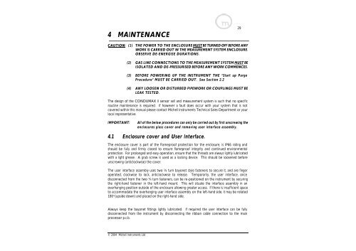
4.1 Enclosure cover and User Interface.<br />
The enclosure cover is part of the Flameproof protection for the enclosure, is IP66 rating and<br />
should be fully and firmly closed to ensure flameproof integrity and continued environmental<br />
protection. For prolonged and easy operation, ensure that the threads are always lightly lubricated<br />
with a light grease. A grub screw is used as a locking device. This should be loosened before<br />
unscrewing (anticlockwise) the cover.<br />
The user interface assembly uses two ¼ turn bayonet style fasteners to secure it, and are finger<br />
operated, clockwise to lock, anticlockwise to release. Temporarily, the user interface, once<br />
disconnected from the two ¼ turn fasteners, can be re-positioned on the instrument by securing<br />
the right-hand fastener in the left-hand mount. This will situate the interface assembly in an<br />
overhanging position outside of the enclosure allowing greater access. If there is insufficient space<br />
to accommodate the overhanging user interface assembly on the left-hand side, it may be rotated<br />
180°(upside down) and placed on the right-hand side.<br />
Always keep the bayonet fittings lightly lubricated. If required the user interface can be fully<br />
disconnected from the instrument by disconnecting the ribbon cable connection to the main<br />
processor p.c.b.<br />
© 2004 Michell Instruments Ltd