Condumax II - Fagerberg
Condumax II - Fagerberg
Condumax II - Fagerberg

You also want an ePaper? Increase the reach of your titles
YUMPU automatically turns print PDFs into web optimized ePapers that Google loves.
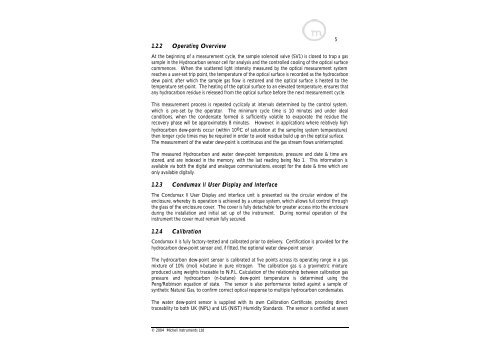
1.2.2 Operating Overview<br />
5<br />
At the beginning of a measurement cycle, the sample solenoid valve (SV1) is closed to trap a gas<br />
sample in the Hydrocarbon sensor cell for analysis and the controlled cooling of the optical surface<br />
commences. When the scattered light intensity measured by the optical measurement system<br />
reaches a user-set trip point, the temperature of the optical surface is recorded as the hydrocarbon<br />
dew point, after which the sample gas flow is restored and the optical surface is heated to the<br />
temperature set-point. The heating of the optical surface to an elevated temperature, ensures that<br />
any hydrocarbon residue is released from the optical surface before the next measurement cycle.<br />
This measurement process is repeated cyclically at intervals determined by the control system,<br />
which is pre-set by the operator. The minimum cycle time is 10 minutes and under ideal<br />
conditions, when the condensate formed is sufficiently volatile to evaporate the residue the<br />
recovery phase will be approximately 8 minutes. However, in applications where relatively high<br />
hydrocarbon dew-points occur (within 10 o C of saturation at the sampling system temperature)<br />
then longer cycle times may be required in order to avoid residue build up on the optical surface.<br />
The measurement of the water dew-point is continuous and the gas stream flows uninterrupted.<br />
The measured Hydrocarbon and water dew-point temperature, pressure and date & time are<br />
stored, and are indexed in the memory, with the last reading being No 1. This information is<br />
available via both the digital and analogue communications, except for the date & time which are<br />
only available digitally.<br />
1.2.3 <strong>Condumax</strong> <strong>II</strong> User Display and Interface<br />
The <strong>Condumax</strong> <strong>II</strong> User Display and interface unit is presented via the circular window of the<br />
enclosure, whereby its operation is achieved by a unique system, which allows full control through<br />
the glass of the enclosure cover. The cover is fully detachable for greater access into the enclosure<br />
during the installation and initial set up of the instrument. During normal operation of the<br />
instrument the cover must remain fully secured.<br />
1.2.4 Calibration<br />
<strong>Condumax</strong> <strong>II</strong> is fully factory-tested and calibrated prior to delivery. Certification is provided for the<br />
hydrocarbon dew-point sensor and, if fitted, the optional water dew-point sensor.<br />
The hydrocarbon dew-point sensor is calibrated at five points across its operating range in a gas<br />
mixture of 10% (mol) n-butane in pure nitrogen. The calibration gas is a gravimetric mixture<br />
produced using weights traceable to N.P.L. Calculation of the relationship between calibration gas<br />
pressure and hydrocarbon (n-butane) dew-point temperature is determined using the<br />
Peng/Robinson equation of state. The sensor is also performance tested against a sample of<br />
synthetic Natural Gas, to confirm correct optical response to multiple hydrocarbon condensates.<br />
The water dew-point sensor is supplied with its own Calibration Certificate, providing direct<br />
traceability to both UK (NPL) and US (NIST) Humidity Standards. The sensor is certified at seven<br />
© 2004 Michell Instruments Ltd