Easi cast caisson units.pdf - FP McCann Ltd
Easi cast caisson units.pdf - FP McCann Ltd
Easi cast caisson units.pdf - FP McCann Ltd

Create successful ePaper yourself
Turn your PDF publications into a flip-book with our unique Google optimized e-Paper software.
2010 Version 1<br />
Caisson<br />
Units<br />
Contents<br />
<strong>FP</strong> <strong>McCann</strong> Caisson Range 1<br />
<strong>FP</strong> M c Cann<br />
pre<strong>cast</strong>@fpmccann.co.uk<br />
Building Manual 1 Piece 2-5<br />
Building Manual 2 Piece 6-10<br />
www.fpmccann.co.uk
<strong>FP</strong> M c Cann<br />
Pre<strong>cast</strong> Concrete Systems<br />
P1<br />
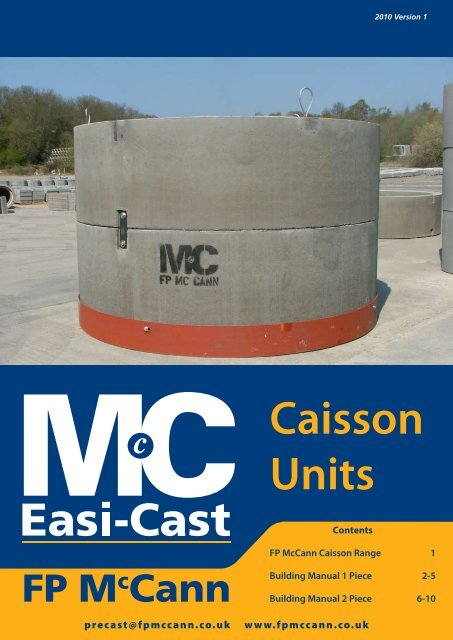
<strong>FP</strong> M c Cann Caisson Units<br />
<strong>FP</strong> <strong>McCann</strong> manufactures a range of reinforcing <strong>units</strong> suitable for sinking by the <strong>caisson</strong> method. Caisson shaft<br />
<strong>units</strong> can be supplied with diameters of 2100mm up to 4000mm. Caissons are manufactured in accordance with<br />
the requirements of BS EN 1916:2002, and have Kitemark certification where relevant to the scope of BS5911-3:2002<br />
(2100mm – 3000mm diameters). However 3600mm and 4000mm diameters remain operative within the scope of the<br />
ISO9001:2000 accredited Quality Management System.<br />
Open <strong>caisson</strong>-sinking techniques permit a shaft structure to be progressively sunk, either under its own weight or<br />
with the aid of <strong>caisson</strong> jacks, in a controlled manner from the surface to a predetermined depth. Caisson shafts are<br />
constructed using a metal cutter ring and base section with rings being added on top as excavation proceeds. The<br />
technique is suited to shaft construction through weak soils, high-plasticity clays, silts, sands and gravels; particularly<br />
below the water table.<br />
<strong>FP</strong> <strong>McCann</strong> Caisson Range<br />
Caissons Shafts<br />
DN<br />
Available Depths (mm) Barrel DN Wall Thickness Lifting Hole<br />
mm 1000 750 500 mm mm Qty per unit<br />
2100 √ √ √ 2420 160<br />
2400 √ √ √ 2760 180<br />
2700 √ √ √ 3060 180<br />
3000 √ √ √ 3420 210<br />
3600 √ √ √ 3970 185<br />
4000* √ √ X 4400 200<br />
*DN4000 supplied as a two piece unit.<br />
Caisson Rings – Table of Weights (DN 2100-4000)<br />
Caissons<br />
Shafts DN<br />
Cutting Shoe Weight (Kg)<br />
Approx. Weight p/meter Caisson<br />
(with cutting shoe) (Kg)**<br />
3 No. RD30 Wavy<br />
Tail Inserts<br />
3 No. RD30 Wavy<br />
Tail Inserts<br />
3 No. RD30 Wavy<br />
Tail Inserts<br />
3 No. RD30 Wavy<br />
Tail Inserts<br />
3 No. RD30 Wavy<br />
Tail Inserts<br />
6 No. RD36 Wavy<br />
Tail Inserts<br />
Approx. Weight p/meter Caisson<br />
(without cutting shoe)**<br />
mm 10mm 20mm 10mm 20mm Kg<br />
2100 286 572 3240 3530 2950<br />
2400 341 682 4130 4480 3790<br />
2700 383 766 4620 5000 4230<br />
3000 454 908 5960 6410 5510<br />
3600 501 1002 6220 6720 5720<br />
4000* 572 1144 7430 8010 6860<br />
* DN4000 supplied as a two piece unit.<br />
** Nominal weights increase by 5% for sizing lifting equipment and reduce by 5% for floatation design.<br />
Base <strong>units</strong> may be fitted with a light duty (10mm) or a medium duty (20mm) cutting shoe.<br />
1 www.fpmccann.co.uk pre<strong>cast</strong>@fpmccann.co.uk
<strong>FP</strong> M c Cann<br />
Pre<strong>cast</strong> Concrete Systems<br />
P2<br />
Building Manual - One Piece<br />
Building Manual for <strong>FP</strong> <strong>McCann</strong> One Piece Caisson Units<br />
(To be read in conjunction with the Caisson Unit Safety Data Sheet)<br />
Caisson ring types provided by <strong>FP</strong> <strong>McCann</strong>:<br />
1. One piece standard <strong>units</strong>, sizes, 2.100m, 2.400m, 2.700m, 3.000m, 3.600m internal diameter <strong>units</strong>. Units depths<br />
available 1.000m, 0.750m and 0.500m.<br />
2.Special Base fitted with a light or medium duty steel cutting shoe *.<br />
* heavy duty cutting shoe made to order<br />
Unit Handling<br />
1. Lifting<br />
All <strong>units</strong> are lifted using 3 number threaded lifting loops** which locate into threaded<br />
lifting sockets, <strong>cast</strong> into the segments, all of which must be used. The chain angle<br />
should not be less than 60 degrees to the horizontal. Refer to diagram below for<br />
explanation of minimum chain angle. Alternatively a spreader beam may be used. The<br />
Safety Data Sheet provides the relevant information with regard to unit weights and<br />
chain lengths.<br />
** All lifting loop devices are proof loaded before dispatch and labelled with a unique code<br />
number. If reused the lifting loop manufacturer’s details must be referred to for instruction<br />
on inspection and testing.<br />
2. Storage / Stacking<br />
Units are stacked vertically. The first unit should be placed on two timber bearers on<br />
even and firm ground. Subsequent <strong>units</strong>, placed on top, should be separated with two<br />
timber bearers. Further measures will need to be taken to ensure the stacks are stable.<br />
The maximum height the <strong>units</strong> should be stacked is 2m unless otherwise instructed<br />
by the Site Engineer.<br />
2 www.fpmccann.co.uk pre<strong>cast</strong>@fpmccann.co.uk
<strong>FP</strong> M c Cann<br />
Pre<strong>cast</strong> Concrete Systems<br />
P3<br />
Building Manual - One Piece<br />
Shaft design<br />
The <strong>units</strong> are designed by <strong>FP</strong> <strong>McCann</strong> for handling and installation only. The overall shaft design should be undertaken<br />
by the Scheme Engineer. For advice contact <strong>FP</strong> <strong>McCann</strong> Technical Department.<br />
Joint seal<br />
All rings have a tongue and groove circle joint which has been designed to incorporate a bitumen rubber compressible.<br />
The seal should be fitted on site just prior to installation.<br />
Building Sequence<br />
The sequence of installation described in this document is indicative only and the exact method of installation is<br />
the responsibility of the Contractor. Health and Safety measures that apply specifically to the <strong>caisson</strong> <strong>units</strong> and their<br />
fittings are indicated, other measures that apply to the shaft construction e.g. temporary guard rails to the top of the<br />
shaft, are the responsibility of the Contractor.<br />
Building Sequence<br />
The shaft may be sunk using a <strong>FP</strong> <strong>McCann</strong> standard concrete ring fitted with a steel cutting edge. The installation<br />
should proceed as follows:<br />
• Excavate a circular hole, typically to accommodate one or two rings and a concrete collar.<br />
• Build the first ring (incorporating cutting edge) to correct line and level<br />
• Wrap sheets of polystyrene or other suitable material around the external face of the unit(s) to provide an annulus<br />
between the collar and the rings, which can be filled with bentonite slurry if required.<br />
• Pour the concrete collar. Note: The collar should be of sufficient size and strength to be capable of supporting the<br />
hydraulic rams (if required).<br />
• Install the hydraulic rams (if required).<br />
3 www.fpmccann.co.uk pre<strong>cast</strong>@fpmccann.co.uk
<strong>FP</strong> M c Cann<br />
Pre<strong>cast</strong> Concrete Systems<br />
P4<br />
Building Manual - One Piece<br />
When building the next and subsequent rings, follow the sequence as described below:<br />
• Fit the compressible seal and along the circle joint groove of the built ring.<br />
• Lower the unit onto the ring built previously aligning the fixing sockets <strong>cast</strong> into the external face of each unit.<br />
• Fix each plate with 2 no M20 bolts using the adjusting washer to correct for alignment and level. Note: 3 number<br />
plates per unit.<br />
• Push the rings into the ground using the hydraulic rams or suitable kentledge spread evenly about the ring. Use<br />
bentonite slurry within the annulus around the shaft to assist sinking if required.<br />
• Excavate the ground within the built rings. Care should be taken not over excavate to ensure that the shaft does<br />
not sink in an uncontrolled way.<br />
• Push the rings to a depth to enable the next ring to be erected. Build the next ring as described above and repeat<br />
the process until the desired depth is achieved.<br />
• Drill the <strong>units</strong> as required to provide holes for grouting. Grout the shaft.<br />
• A base slab may then be <strong>cast</strong> within the bottom of the shaft. The installation of seals will be required to avoid<br />
tracking of water between the base slab and the rings. For advice contact <strong>FP</strong> <strong>McCann</strong> Technical Department.<br />
4 www.fpmccann.co.uk pre<strong>cast</strong>@fpmccann.co.uk
<strong>FP</strong> M c Cann<br />
Pre<strong>cast</strong> Concrete Systems<br />
P5<br />
Building Manual - One Piece<br />
Ancillary Items<br />
• Available from <strong>FP</strong> <strong>McCann</strong> or recommend specialist supplier<br />
Shaft slabs<br />
• Pre <strong>cast</strong> cover and landing slabs.<br />
Shaft specialist building equipment<br />
• Bitumen rubber circle joint seal<br />
• Lifting loops<br />
5 www.fpmccann.co.uk pre<strong>cast</strong>@fpmccann.co.uk
<strong>FP</strong> M c Cann<br />
Pre<strong>cast</strong> Concrete Systems<br />
P6<br />
Building Manual - Two Piece<br />
Building Manual for <strong>FP</strong> <strong>McCann</strong> Two Piece Caisson Units<br />
(To be read in conjunction with the Caisson Unit Safety Data Sheet)<br />
Caisson ring types provided by <strong>FP</strong> <strong>McCann</strong>:<br />
1. Two piece standard unit size 4.000m internal diameter <strong>units</strong>. Unit depths available<br />
1.000m and 0.750m.<br />
2. Special bases fitted with a light or medium duty steel cutting shoe *.<br />
* heavy duty cutting shoe made to order<br />
Unit Handling<br />
1. Lifting<br />
Single <strong>units</strong> (half ring) are lifted using 3 number threaded lifting loops** which<br />
locate into threaded lifting sockets, <strong>cast</strong> into the <strong>units</strong> , all of which must be used.<br />
The chain angle should not be less than 60 degrees to the horizontal. In order to lift<br />
without tilt the chain lengths will differ. Refer to diagram below for explanation of<br />
minimum chain angle and lengths. Alternatively a spreader beam may be used.<br />
Complete <strong>units</strong> (full ring) are lifted using 4 number threaded lifting loops** which<br />
locate into threaded lifting sockets <strong>cast</strong> into the <strong>units</strong>. Refer to diagram below for explanation of the location of<br />
the lifting sockets to be used. The chain angle should not be less than 60 degrees to the horizontal. Alternatively a<br />
spreader beam may be used Note: Using 3 chains will put unforeseen stresses on the concrete and may cause the<br />
concrete around the join to crack). The Safety Data Sheet provides the relevant information with regard to unit<br />
weights and chain lengths.<br />
** All lifting loop devices are proof loaded before dispatch and labelled with a unique code number. If reused the lifting loop<br />
manufacturer’s details must be referred to for instruction on inspection and testing.<br />
chain length to be<br />
3565mm assuming<br />
60° lift<br />
chain length to be<br />
3146mm assuming<br />
60° lift<br />
4 no. chains length to be<br />
4205mm assuming 60° lift<br />
6 www.fpmccann.co.uk pre<strong>cast</strong>@fpmccann.co.uk
<strong>FP</strong> M c Cann<br />
Pre<strong>cast</strong> Concrete Systems<br />
P7<br />
Building Manual - Two Piece<br />
2. Storage / Stacking<br />
Units are stacked vertically. The first unit should be placed on two timber bearers on even and firm ground. Subsequent<br />
<strong>units</strong>, placed on top, should be separated with two timber bearers. Further measures will need to be taken to ensure<br />
the stacks are stable. The maximum height the <strong>units</strong> should be stacked is 2m unless otherwise instructed by the Site<br />
Engineer.<br />
Shaft design<br />
The <strong>units</strong> are designed by <strong>FP</strong> <strong>McCann</strong> for handling and installation only. The overall shaft design should be undertaken<br />
by the Scheme Engineer. For advice contact <strong>FP</strong> <strong>McCann</strong> Technical Department.<br />
Joint seal<br />
All rings have a tongue and groove circle joint which has been designed to incorporate a bitumen rubber compressible<br />
seal. The seal should be fitted on site just prior to installation.<br />
Building Sequence<br />
The sequence of installation described in this document is indicative only and the exact method of installation is<br />
the responsibility of the Contractor. Health and Safety measures that apply specifically to the <strong>caisson</strong> <strong>units</strong> and their<br />
fittings are indicated, other measures that apply to the shaft construction e.g. temporary guard rails to the top of the<br />
shaft, are the responsibility of the Contractor.<br />
It is recommended that two piece <strong>caisson</strong>s are jointed before lifting into place.<br />
Place the two <strong>units</strong> on a level surface, ideally on 2 no skids to reduce resistance when jointing and also to maintain a<br />
clean joint.<br />
Place both halves side by side ensuring both are at the correct orientation i.e. with bolt holes in line with threaded<br />
sockets.<br />
Insert the M24x200 threaded pin with the 60mm threaded side placed into the <strong>cast</strong> in sockets.<br />
Place the butyl rubber sealant along the vertical joint on both halves of ring.<br />
Once bolts and sealant are in position, the 2 halves of the unit must be pulled together using a ratchet system e.g. a<br />
chain block fixed to the <strong>cast</strong> in M24x80 sockets on opposite ends of the <strong>units</strong>. (Do not use the bolting system to pull<br />
the <strong>units</strong> together as this may crack the concrete and damage the joint)<br />
7 www.fpmccann.co.uk pre<strong>cast</strong>@fpmccann.co.uk
<strong>FP</strong> M c Cann<br />
Pre<strong>cast</strong> Concrete Systems<br />
P8<br />
Building Manual - Two Piece<br />
Building Sequence<br />
The shaft may be sunk using a <strong>FP</strong> <strong>McCann</strong> standard concrete ring fitted with a steel cutting edge. The installation<br />
should proceed as follows:<br />
• Excavate a circular hole, typically to accommodate one or two rings and a concrete collar.<br />
• Build the first ring (incorporating cutting edge) to correct line and level<br />
• Wrap sheets of polystyrene or other suitable material around the external face of the unit(s) to provide an annulus<br />
between the collar and the rings, which can be filled with bentonite slurry if required.<br />
• Pour the concrete collar. Note: The collar should be of sufficient size and strength to be capable of supporting the<br />
hydraulic rams (if required).<br />
• Install the hydraulic rams (if required).<br />
8 www.fpmccann.co.uk pre<strong>cast</strong>@fpmccann.co.uk
<strong>FP</strong> M c Cann<br />
Pre<strong>cast</strong> Concrete Systems<br />
P9<br />
Building Manual - Two Piece<br />
When building the next and subsequent rings, follow the sequence as described below:<br />
• Fit the compressible seal and along the circle joint groove of the built ring.<br />
• Lower the unit onto the ring built previously aligning the fixing sockets <strong>cast</strong> into the external face of each unit.<br />
• Fix each plate with 2 no M20 bolts using the adjusting washer to correct for alignment and level. Note: 4 number<br />
plates per ring.<br />
• Push the rings into the ground using the hydraulic rams or suitable kentledge spread evenly about the ring. Use<br />
bentonite slurry within the annulus around the shaft to assist sinking if required.<br />
• Excavate the ground within the built rings. Care should be taken not over excavate to ensure that the shaft does<br />
not sink in an uncontrolled way.<br />
• Push the rings to a depth to enable the next unit to be erected. Build the next ring as described above and the<br />
process repeated until the desired depth is achieved.<br />
• Drill the <strong>units</strong> as required to provide holes for grouting. Grout the shaft.<br />
• A base slab may then be <strong>cast</strong> within the bottom of the shaft. The installation of seals will be required to avoid<br />
tracking of water between the base slab and the rings. For advice contact <strong>FP</strong> <strong>McCann</strong> Technical Department.<br />
9 www.fpmccann.co.uk pre<strong>cast</strong>@fpmccann.co.uk
<strong>FP</strong> M c Cann<br />
Pre<strong>cast</strong> Concrete Systems<br />
P10<br />
Building Manual - Two Piece<br />
Ancillary Items<br />
• Available from <strong>FP</strong> <strong>McCann</strong> or recommend specialist supplier<br />
Shaft slabs<br />
• Pre <strong>cast</strong> cover and landing slabs.<br />
Shaft specialist building equipment<br />
• Bitumen rubber vertical and circle joint seal<br />
• Lifting loops<br />
10 www.fpmccann.co.uk pre<strong>cast</strong>@fpmccann.co.uk
Pre<strong>cast</strong> Office Locations<br />
Ellistown<br />
Whitehill Road<br />
Leicestershire<br />
England<br />
LE67 1ET<br />
Alnwick<br />
Little Houghton<br />
Northumberland<br />
England<br />
NE66 3JX<br />
Telford<br />
Doseley<br />
Telford<br />
Shropshire<br />
TF4 3BX<br />
Cadeby<br />
Brasscote Lane<br />
Cadeby, Nuneaton<br />
Warks<br />
CV13 0BB<br />
Tel: 01530 240000<br />
Fax: 01530 240013<br />
Tel: 01665 577653<br />
Fax: 01665 577711<br />
Tel: 01952 630300<br />
Fax: 01952 501537<br />
Tel: 01455 290780<br />
Fax: 01455 292189<br />
Pre<strong>cast</strong> Head Office<br />
Knockloughrim Quarry<br />
3 Drumard Road<br />
Magherafelt<br />
BT45 8QA<br />
Tel: 028 7964 2558<br />
Fax: 028 7964 4224<br />
www.fpmccann.co.uk<br />
pre<strong>cast</strong>@fpmccann.co.uk