Genset operation and service manual - Under-Slung ... - Florens
Genset operation and service manual - Under-Slung ... - Florens
Genset operation and service manual - Under-Slung ... - Florens

You also want an ePaper? Increase the reach of your titles
YUMPU automatically turns print PDFs into web optimized ePapers that Google loves.
FIELD<br />
SHUNT<br />
SERIES<br />
rectifier unit. The response time of the excitation system<br />
is very fast since the exciter stator carries an alternating<br />
current corresponding to the load current which appears<br />
immediately on the exciter primary. An increase in load<br />
current will cause an immediate increase in the exciter<br />
secondary output voltage which is rectified <strong>and</strong> applied<br />
to the generator field windings. The inherent<br />
compounding characteristics of the excitation system<br />
provide excellent voltage regulation even under heavy<br />
overload conditions.<br />
STATOR<br />
GENERATOR<br />
STATOR<br />
L<br />
O<br />
A<br />
D<br />
1<br />
7<br />
6<br />
2<br />
3<br />
5<br />
ROTOR<br />
RECTIFIER<br />
ASSEMBLY<br />
EXCITER<br />
4<br />
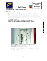
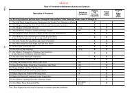
Figure 1-5. A-C Generator Circuit Diagram<br />
1.5 ALTERNATING CURRENT GENERATOR<br />
1.5.1 Principle of Operation<br />
The Marathon Alternator Company (Lima) brushless<br />
A-C generator (10, Figure 1-2) is a self-regulated,<br />
rotating field synchronous unit. The generator stator<br />
<strong>and</strong> exciter stator are combined in a common housing.<br />
The generator field, exciter rotor <strong>and</strong> rotating rectifier<br />
assembly are mounted on a common shaft. The output<br />
of the exciter rotor is applied to the generator field<br />
winding through a rotating, full-wave bridge, silicon<br />
rectifier unit.<br />
All connections between the exciter stator windings <strong>and</strong><br />
the generator stator windings internal within the stator<br />
housing. Only the output power leads are connected at<br />
the terminal box, located on top of the generator.<br />
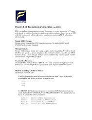
1.5.2 Alternating Current Generator Diagram<br />
Figure 1-5 shows the internal schematic diagram of the<br />
generator, exciter <strong>and</strong> rectifier unit. The generator is a<br />
three phase unit <strong>and</strong> the exciter stator <strong>and</strong> exciter rotor<br />
also have three phase windings. A portion of the exciter<br />
stator windings is connected across a tap on the<br />
generator stator winding. This exciter shunt winding<br />
provides the generator field excitation power required<br />
for the generator no-load voltage. Another portion of the<br />
exciter stator windings is connected in series with the<br />
output of the generator <strong>and</strong> provides a compounding<br />
excitation characteristic.<br />
The rotor is, in effect, the secondary of a rotating current<br />
transformer induction frequency converter. The exciter<br />
rotor output voltage is applied to the generator field<br />
windings by a three phase full wave rotating silicon<br />
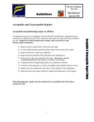
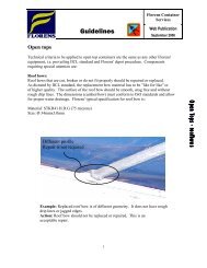
1. AC Tap<br />
2. Back Cover<br />
3. Positive Output(B+)<br />
4. Integral Regulator<br />
5. Excite<br />
6. Ground<br />
7. 12 vdc Test Lamp<br />
Terminal (D+)<br />
1.6 BATTERY CHARGING - ALTERNATOR<br />
CAUTION<br />
Observe proper polarity when installing the<br />
battery or connecting a battery charger, the<br />
negative battery terminal must be<br />
grounded. Reverse polarity may damage<br />
the charging system. When charging the<br />
battery in unit, isolate the battery by<br />
disconnecting the negative battery terminal<br />
first, then the positive. Once the battery has<br />
been charged, connect the positive battery<br />
terminal first, then the negative.<br />
1.6.1 Introduction<br />
The mechanical construction of the alternator differs<br />
from the DC generator in that the field rotates <strong>and</strong> the<br />
(armature) generating windings are stationary. The field<br />
current necessary to control the output of the alternator<br />
is supplied from the solid-state regulator. This integral<br />
voltage regulator controls the current feed to the field via<br />
the brushes <strong>and</strong> rotor slip rings. (See Figure 1-6)<br />
Two completely sealed ball bearings support the rotor in<br />
the front <strong>and</strong> rear housing.<br />
1.6.2 Alternator Operation<br />
1-7 T-266