Genset operation and service manual - Under-Slung ... - Florens
Genset operation and service manual - Under-Slung ... - Florens
Genset operation and service manual - Under-Slung ... - Florens

You also want an ePaper? Increase the reach of your titles
YUMPU automatically turns print PDFs into web optimized ePapers that Google loves.
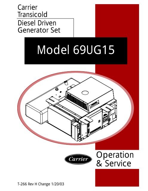
Carrier<br />
Transicold<br />
Diesel Driven<br />
Generator Set<br />
Model 69UG15<br />
Operation<br />
&Service<br />
T-266 Rev H Change 1/20/03
OPERATION AND SERVICE MANUAL<br />
DIESEL DRIVEN GENERATOR SET<br />
MODEL<br />
69UG15<br />
Carrier Transicold<br />
A member of the United Technologies Corporation family. Stock symbol UTX.<br />
Carrier Transicold, Carrier Corporation, P.O. Box 4805, Syracuse, N.Y. 13221 U. S. A.<br />
© 2002Carrier Corporation D Printed in U. S. A. 0602
SAFETY SUMMARY<br />
GENERAL SAFETY NOTICES<br />
The following general safety notices supplement the specific warnings <strong>and</strong> cautions appearing elsewhere in this<br />
<strong>manual</strong>. They are recommended precautions that must be understood <strong>and</strong> applied during <strong>operation</strong> <strong>and</strong> maintenance<br />
of the equipment covered herein. The general safety notices are presented in the following three sections labeled:<br />
First Aid, Operating Precautions <strong>and</strong> Maintenance Precautions. A listing of the specific warnings <strong>and</strong> cautions<br />
appearing elsewhere in the <strong>manual</strong> follows the general safety notices.<br />
FIRST AID<br />
An injury, no matter how slight, should never go unattended. Always obtain first aid or medical attention immediately.<br />
OPERATING PRECAUTIONS<br />
Always wear safety glasses <strong>and</strong> hearing protection.<br />
Keep h<strong>and</strong>s, clothing <strong>and</strong> tools clear of the radiator fan <strong>and</strong> rotating belts.<br />
No work should be performed on the unit until all circuit breakers <strong>and</strong> start-stop switches are turned off <strong>and</strong> the<br />
negative battery terminal has been disconnected..<br />
Always work in pairs. Never work on the equipment alone.<br />
In case of severe vibration or unusual noise, stop the unit <strong>and</strong> investigate.<br />
MAINTENANCE PRECAUTIONS<br />
Be sure power is turned off <strong>and</strong> the negative battery cable is disconnected before working on generator set.<br />
Do not bypass any electrical safety devices, e.g. bridging an overload, or using any sort of jumper wires. Problems with<br />
the system should be diagnosed, <strong>and</strong> any necessary repairs performed, by qualified <strong>service</strong> personnel.<br />
In case of electrical fire, open circuit switch <strong>and</strong> extinguish with CO 2 (never use water).<br />
Fuel Tanks present explosion, fire <strong>and</strong> rupture hazards even if liquid fuel has been drained. Do not attempt any repairs,<br />
especially repairs using flame, welder or torch, unless you haveen properly trained <strong>and</strong> the tank has been emptied of<br />
liquid fuel <strong>and</strong> fuel vapors <strong>and</strong> the tank is properly ventilated.<br />
UNIT LABEL IDENTIFICATION<br />
To help identify the hazard labels on the Unit <strong>and</strong> explain the level of awareness each one carries, explanations with<br />
appropriate consequences are provided below:<br />
DANGER -- indicates an immediate hazard which WILL result in severe personal injury or death.<br />
WARNING -- indicates hazards or unsafe conditions which COULD result in severe personal injury or death.<br />
CAUTION --indicates potential hazards or unsafe practices which COULD result in minor personal injury, product or<br />
property damage.<br />
SPECIFIC WARNING AND CAUTION STATEMENTS<br />
The statements that follow are applicable to the generator set <strong>and</strong> appear elsewhere in this <strong>manual</strong>. These recommended<br />
precautions must be understood <strong>and</strong> applied during <strong>operation</strong> <strong>and</strong> maintenance of the equipment covered<br />
herein.<br />
WARNING<br />
Do not use gasoline to clean air cleaner parts.<br />
WARNING<br />
Beware of moving V-belt, belt driven components <strong>and</strong> hot exhaust components.<br />
WARNING<br />
<strong>Under</strong> no circumstances should ether or any other unauthorized starting aids be used in conjunction<br />
with the glow plugs.<br />
Safety--i T-266
WARNING<br />
Do not direct water or steam into the generator openings. Do not allow any soap <strong>and</strong> water solutions<br />
to enter the alternator.<br />
WARNING<br />
High voltage (dielectric) testing must not be performed to the machine without first observing NEMA<br />
rules. The insulation of this generator winding may be safely checked by using a megger. A high<br />
megger reading indicates good insulation.<br />
CAUTION<br />
Observe proper polarity when installing the battery or connecting a battery charger, the negative battery<br />
terminal must be grounded. Reverse polarity may damage the charging system. When charging<br />
the battery in unit, isolate the battery by disconnecting the negative battery terminal first, then the<br />
positive. Once the battery has been charged, connect the positive battery terminal first, then the negative.<br />
CAUTION<br />
The generator set circuit breaker must be in the ON position in order to supply power to the refrigeration<br />
unit.<br />
Never pour cold water into a hot engine.<br />
CAUTION<br />
CAUTION<br />
Use only ethylene glycol, anti-freeze (with inhibitors) in system as glycol by itself will damage the<br />
cooling system.<br />
CAUTION<br />
Always cover the engine inlet tube while the air cleaner is being <strong>service</strong>d.<br />
CAUTION<br />
Do not underfill or overfill the cups. Overfilling of cups means loss of capacity <strong>and</strong> underfilling<br />
means lack of filtering efficiency.<br />
CAUTION<br />
Continued <strong>operation</strong> with failed shockmounts may result in engine or generator damage.<br />
CAUTION<br />
The rotor should not be pulled out from the alternator more than 0.75 inches. Damage to the bearing<br />
<strong>and</strong> windings may result.<br />
T-266<br />
Safety--ii
TABLE OF CONTENTS<br />
PARAGRAPH NUMBER<br />
Page<br />
SAFETY SUMMARY .................................................................... Safety -i<br />
GENERAL SAFETY NOTICES ............................................................ Safety--i<br />
FIRST AID ............................................................................. Safety--i<br />
OPERATING PRECAUTIONS ............................................................ Safety--i<br />
MAINTENANCE PRECAUTIONS .......................................................... Safety--i<br />
SPECIFIC WARNING AND CAUTION STATEMENTS ........................................ Safety--i<br />
DESCRIPTION ............................................................................... 1-1<br />
1.1 INTRODUCTION ..................................................................... 1-1<br />
1.2 CONFIGURATION IDENTIFICATION ................................................... 1-1<br />
1.3 ENGINE ............................................................................. 1-6<br />
1.3.1 Engine Air System ................................................................ 1-6<br />
1.3.2 Lube Oil Filter Arrangement ........................................................ 1-6<br />
1.3.3 Fuel System ...................................................................... 1-6<br />
1.4 ENGINE SCREW THREADS ........................................................... 1-6<br />
1.5 ALTERNATING CURRENT GENERATOR ............................................... 1-7<br />
1.5.1 Principle of Operation .............................................................. 1-7<br />
1.5.2 Alternating Current Generator Diagram ............................................... 1-7<br />
1.6 BATTERY CHARGING -- ALTERNATOR ................................................. 1-7<br />
1.6.1 Introduction ...................................................................... 1-7<br />
1.6.2 Alternator Operation ............................................................... 1-8<br />
1.6.3 Integral Voltage Regulator Operation (12 volts d-c) ..................................... 1-8<br />
1.7 BATTERY CHARGING -- SOLID STATE SYSTEM ........................................ 1-8<br />
1.8 OPERATING CONTROLS AND INSTRUMENTS ......................................... 1-8<br />
1.8.1 Introduction ...................................................................... 1-8<br />
1.8.2 Control Panel <strong>and</strong> Related Components .............................................. 1-8<br />
1.9 SAFETY DEVICES ................................................................... 1-9<br />
1.10 UNIT SPECIFICATIONS ............................................................... 1-10<br />
1.11 ENGINE DATA ....................................................................... 1-10<br />
OPERATION ................................................................................. 2-1<br />
2.1 GENERATOR SET INSTALLATION AND REMOVAL -- STANDARD MOUNT ................. 2-1<br />
2.2 GENERATOR SET INSTALLATION AND REMOVAL -- QUICK MOUNT ...................... 2-2<br />
2.3 STARTING AND STOPPING INSTRUCTIONS ........................................... 2-3<br />
2.3.1 Pre-Start Inspection ............................................................... 2-3<br />
2.3.2 Starting Insturctions ............................................................... 2-3<br />
2.3.3 Post-Start Inspection .............................................................. 2-3<br />
2.3.4 Stopping Instructions .............................................................. 2-3<br />
2.4 CONTROL CIRCUIT OPERATION ...................................................... 2-3<br />
2.4.1 Sequence Of Operation (Units using Figure 5-2) ....................................... 2-3<br />
2.4.2 Sequence Of Operation (Units using Figure 5-6) ....................................... 2-4<br />
i<br />
T--266
TABLE OF CONTENTS - Continued<br />
PARAGRAPH NUMBER<br />
Page<br />
TROUBLESHOOTING ......................................................................... 3-1<br />
3.1 DIESEL ENGINE ..................................................................... 3-1<br />
3.1.1 Engine Will Not Start .............................................................. 3-1<br />
3.1.2 Engine Starts Then Stops .......................................................... 3-1<br />
3.1.3 Engine Will Not Shut Off ........................................................... 3-1<br />
3.1.4 Starter Motor Malfunction .......................................................... 3-2<br />
3.1.5 Malfunction In The Engine Starting Circuit ............................................ 3-2<br />
3.1.6 Miscellaneous Engine Troubleshooting ............................................... 3-2<br />
3.2 BATTERY CHARGING ALTERNATOR .................................................. 3-3<br />
3.3 BATTERY CHARGER (SOLID STATE) .................................................. 3-3<br />
3.4 ALTERNATING CURRENT GENERATOR ............................................... 3-4<br />
SERVICE AND PREVENTIVE MAINTENANCE ................................................... 4-1<br />
4.1 INTRODUCTION ..................................................................... 4-1<br />
4.2 PREVENTIVE MAINTENANCE SCHEDULE ............................................. 4-1<br />
4.3 BATTERY SERVICE .................................................................. 4-1<br />
4.4 ENGINE SERVICE AND COMPONENTS ................................................ 4-1<br />
4.4.1 Priming The Fuel System .......................................................... 4-1<br />
4.4.2 Servicing Fuel Pump Internal Filter .................................................. 4-1<br />
4.4.3 Fuel Filter ........................................................................ 4-1<br />
4.4.4 Cooling System ................................................................... 4-1<br />
4.4.5 Servicing And Adjusting V-belt ...................................................... 4-4<br />
4.4.6 Lube Oil Filter .................................................................... 4-4<br />
4.4.7 Adjusting Engine Speed ............................................................ 4-4<br />
4.4.8 Engine Air Cleaner ................................................................ 4-4<br />
4.4.9 Engine Crankcase Breather ........................................................ 4-5<br />
4.4.10 Servicing Glow Plugs .............................................................. 4-5<br />
4.5 SERVICING THE ALTERNATING CURRENT GENERATOR ............................... 4-6<br />
4.5.1 Preventive Maintenance <strong>and</strong> Operating Precautions ................................... 4-6<br />
4.5.2 Generator Repair/Test Procedures ................................................... 4-6<br />
4.5.3 Bearing Replacement .............................................................. 4-7<br />
4.5.4 Generator Installation <strong>and</strong> Removal .................................................. 4-8<br />
4.6 GENERAL GENERATOR SET MAINTENANCE .......................................... 4-8<br />
4.6.1 Maintenance Of Painted Surfaces ................................................... 4-8<br />
4.6.2 Checking And Replacing Shockmounts ............................................... 4-8<br />
4.7 SERVICING THE ALTERNATOR ....................................................... 4-9<br />
4.7.1 Preliminary Checks <strong>and</strong> Tests ....................................................... 4-9<br />
4.7.2 Test Tools ........................................................................ 4-10<br />
4.7.3 Problem Area Determination ........................................................ 4-10<br />
4.7.4 In-Unit Alternator/Regulator Tests ................................................... 4-10<br />
4.7.5 Alternator Brush Test Procedure ..................................................... 4-11<br />
4.7.6 Slip Ring Servicing ................................................................ 4-11<br />
4.7.7 Alternator Installation .............................................................. 4-12<br />
4.8 UNIDRIVE TORQUE REQUIREMENTS ................................................. 4-12<br />
SCHEMATICS ................................................................................ 5-1<br />
5.1 INTRODUCTION ..................................................................... 5-1<br />
T--266<br />
ii
LIST OF ILLUSTRATIONS<br />
FIGURE NUMBER<br />
Page<br />
Figure 1-1. Generator Set -- Control Box (Road) Side .............................................. 1-4<br />
Figure 1-2. Generator Set -- Top View with Top Frame Members Removed for Clarity .................. 1-5<br />
Figure 1-3. Fuel System Diagram ............................................................... 1-6<br />
Figure 1-4. Lube Oil .......................................................................... 1-6<br />
Figure 1-5. A-C Generator Circuit Diagram ....................................................... 1-7<br />
Figure 1-6. Alternator <strong>and</strong> Regulator ............................................................ 1-8<br />
Figure 1-7. Alternator Schematic Diagram ....................................................... 1-8<br />
Figure 1-8. Control Box <strong>and</strong> Panel .............................................................. 1-9<br />
Figure 2-1. Generator Set Mounting -- St<strong>and</strong>ard Mount ............................................ 2-1<br />
Figure 2-2. Generator Set Mounting -- Quick Mount ............................................... 2-2<br />
Figure 4-1. Mechanical Fuel Pump .............................................................. 4-1<br />
Figure 4-2. Engine Speed Adjustment ........................................................... 4-4<br />
Figure 4-3. Air Filter .......................................................................... 4-5<br />
Figure 4-4. Engine Crankcase Breather ......................................................... 4-5<br />
Figure 4-5. A-C Generator Rectifier Assembly .................................................... 4-7<br />
Figure 4-6. Rectifier Removal .................................................................. 4-7<br />
Figure 4-7. Engine Shockmounts ............................................................... 4-9<br />
Figure 4-8. Generator Shockmounts ............................................................ 4-9<br />
Figure 4-9. Open Diode-Trio Test ............................................................... 4-10<br />
Figure 4-10. Open Regulator Test .............................................................. 4-11<br />
Figure 4-11. Alternator Output Test ............................................................. 4-11<br />
Figure 4-12. Alternator Brush Assembly ......................................................... 4-11<br />
Figure 4-13. Unidrive Torque Requirements ...................................................... 4-13<br />
Figure 5-1 Schematic Diagram ................................................................. 5-2<br />
Figure 5-2 Schematic Diagram ................................................................. 5-3<br />
Figure 5-3 Schematic Diagram ................................................................. 5-4<br />
Figure 5-4 Schematic Diagram ................................................................. 5-5<br />
Figure 5-5 Schematic Diagram ................................................................. 5-6<br />
Figure 5-6 Schematic Diagram ................................................................. 5-7<br />
Figure 5-7 Schematic Diagram ................................................................. 5-8<br />
Figure 5-8 Schematic Diagram ................................................................. 5-9<br />
LIST OF TABLES<br />
TABLE NUMBER<br />
Page<br />
Table 1-1. Model Chart ......................................................................... 1-1<br />
Table 1-2. Safety Devices ...................................................................... 1-10<br />
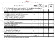
Table 4-1 Preventative Maintenance Actions <strong>and</strong> Schedule .......................................... 4-2<br />
iii<br />
T--266
1.1 INTRODUCTION<br />
The carrier Transicold model 69UG15 under-mounted<br />
diesel-driven generator sets serve to provide electrical<br />
power for all-electric refrigeration units.<br />
The generator set (see Figure 1-1 <strong>and</strong> Figure 1-2)<br />
consist of a diesel engine direct connected to an<br />
alternating current generator <strong>and</strong> mounted in a<br />
structural steel frame. The engine is a vertical in--line,<br />
four cylinder diesel manufactured by Kubota while the<br />
generator is a 15 KW, brushless, single bearing type<br />
manufactured by Lima. The generator provides a<br />
constant 460 or 230 vac, 3 phase, 60 hertz electrical<br />
supply.<br />
Electrical controls are mounted in a control box with<br />
operating controls <strong>and</strong> gauges mounted on a control<br />
panel (which also serves as the control box cover). The<br />
control panel components are protected by a deflector<br />
assembly or a windowed control box door.<br />
Auxiliary engine equipment consists of the starting<br />
battery, battery charging system (alternator or solid<br />
state), glow plugs (used as a starting aid), “spin-on” lube<br />
oil <strong>and</strong> fuel filters (for easier filter changes) <strong>and</strong> other<br />
necessary components for proper unit <strong>operation</strong>. The<br />
water pump <strong>and</strong> the radiator cooling fan are belt-driven<br />
from the engine crankshaft. All references to engine are<br />
as viewed from the fly wheel end.<br />
1.2 CONFIGURATION IDENTIFICATION<br />
Generator set identification information is provided on a<br />
plate located inside the engine inspection door (see<br />
A1<br />
A2<br />
--<br />
--<br />
50 Gallon Integral Tank (Side Fill -- Steel)<br />
50 Gallon Integral Tank (Top Fill -- Steel)<br />
A3<br />
A4<br />
--<br />
--<br />
65 Gallon Integral Tank (Steel)<br />
50 Gallon Remote Tank (Steel)<br />
A5<br />
A6<br />
--<br />
--<br />
75 Gallon Remote Tank (Steel)<br />
50 Gallon Remote Tank (Aluminium)<br />
SECTION 1<br />
DESCRIPTION<br />
Table 1-1. Model Chart<br />
LEGEND<br />
Figure 1-2). The plate provides the generator set model<br />
number, serial number <strong>and</strong> parts identification number<br />
(PID). The model number identifies the overall<br />
configuration while the PID provides information on<br />
specific optional equipment <strong>and</strong> differences in detailed<br />
parts. Configuration identification for models covered<br />
herein are provided in Table 1-1. The model number,<br />
serial number <strong>and</strong> PID number must be included when<br />
ordering parts <strong>and</strong> inquiring about your unit.<br />
Separately bound <strong>manual</strong>s covering the diesel engine<br />
<strong>and</strong> Auto Restart Option are also available, see the<br />
following chart. Note, all referenced engines have been<br />
assembled using the two piece oil pan<br />
Manual/Form<br />
No.<br />
Equipment<br />
Covered<br />
Type of<br />
Manual<br />
62-03741* CT4-134-DI-B Workshop<br />
62-03459* CT4-134-DI-B Engine Parts List<br />
62-10301** CT4-134-DI Workshop<br />
62-10295** CT4-134-DI Engine Parts List<br />
62-10411 Auto Restart Supplement<br />
*Prior to Serial Number XA0001<br />
** Starting with Serial Number XA0001<br />
B1 -- 460 Volt<br />
B2 -- 230 Volt<br />
C1 -- No Voltmeter, Blank-Off Plate<br />
C2 -- With Voltmeter (Greenb<strong>and</strong>)<br />
Model<br />
PID<br />
Electrical Wiring<br />
Schematic <strong>and</strong><br />
Diagram Figures<br />
Fuel Tank Voltage Voltmeter<br />
69UG15-111-1 UG0249 5-1, 5-2, 5-4 A2 B2 C2<br />
UG0026 5-1, 5-2, 5-3 A1 B1 C1<br />
UG0030 5-1, 5-2, 5-3 A1 B1 C2<br />
UG0031 5-1, 5-2, 5-3 A1 B1 C1<br />
UG0045 5-1, 5-2, 5-3 A1 B1 C2<br />
UG0048 5-1, 5-2, 5-3 A1 B1 C2<br />
69UG15-121-2121 2<br />
UG0052 5-1, 5-2, 5-3, 5-4 A1 B1/B2 C2<br />
UG0077 5-1, 5-2, 5-3 A1 B1 C2<br />
UG0100 5-1, 5-2, 5-3 A1 B1 C2<br />
UG0128 5-1, 5-2, 5-3 A2 B1 C2<br />
UG0195 5-1, 5-2, 5-3 A2 B1 C2<br />
UG0227 5-1, 5-2, 5-3 A2 B1 C2<br />
UG0276 5-1, 5-2, 5-3 A2 B1 C1<br />
1-1 T-266
Table 1-1. Model Chart - Continued<br />
Electrical Wiring<br />
Model<br />
PID Schematic <strong>and</strong><br />
Diagram Figures<br />
Fuel Tank Voltage Voltmeter<br />
69UG15-121-3121 UG0025 5-1, 5-2, 5-3 A1 B1 C1<br />
UG0034 5-1, 5-2, 5-3 A1 B1 C1<br />
UG0063 5-1, 5-2, 5-3 A1 B1 C2<br />
69UG15-121-5 121 5 UG0149 5-1, 5-2, 5-3 A2 B1 C2<br />
UG0221 5-1, 5-2, 5-3 A2 B1 C2<br />
69UG15-121-7 UG0164 5-1, 5-2, 5-3 A2 B1 C1<br />
69UG15-121-8121 UG0155 5-1, 5-2, 5-3 A2 B1 C1<br />
UG0196 5-1, 5-2, 5-3 A2 B1 C1<br />
69UG15-211-1 UG0172 5-1, 5-2, 5-4 A2 B2 C2<br />
UG0049 5-1, 5-2, 5-3 A1 B1 C2<br />
UG0114 5-1, 5-2, 5-3 A1 B1 C2<br />
69UG15-221-2 2 UG0130 5-1, 5-2, 5-3 A1 B1 C2<br />
UG0148 5-1, 5-2, 5-3 A1 B1 C2<br />
UG0217 5-1, 5-2, 5-3 A2 B1 C2<br />
69UG15-221-3 UG0229 5-1, 5-2, 5-3, 5-4 A2 B1/B2 C2<br />
69UG15-221-4 UG0256 5-1, 5-2, 5-3 A2 B1 C2<br />
69UG15-321-1 UG0248 5-1, 5-2, 5-3 A5 B1 C2<br />
69UG15-321-2 UG0179 5-1, 5-2, 5-3 A5 B1 C2<br />
69UG15-321-5<br />
5<br />
UG0203 5-1, 5-2, 5-3 A6 B1 C1<br />
UG0291 5-1, 5-2, 5-3 A6 B1 C1<br />
69UG15-421-1 UG0255 5-1, 5-2, 5-3 A3 B1 C2<br />
69UG15-521-8 UG0234 5-1, 5-2, 5-3 A3 B1 C1<br />
NOTE: In early 1998, Carrier Transicold began implementing a new model numbering system. The following<br />
models use this new system.<br />
UG0351 5-1, 5-2, 5-3 A2 B1 C1<br />
UG0413 5-1, 5-2, 5-3 A2 B1 C2<br />
69UG15-050Q-01 01 UG0497 5-5, 5-6, 5-7 A2 B1 C2<br />
UG0524 5-5, 5-6, 5-7 A2 B1 C2<br />
UG0560 5-5, 5-6, 5-7 A2 B1 C2<br />
69UG15-050Q-02<br />
02<br />
UG0426 5-5, 5-6, 5-7 A2 B1 C1<br />
UG0688 5-5, 5-6, 5-7 A2 B1 C1<br />
UG0427 5-5, 5-6,5-7 A6 B1 C1<br />
69UG15-050R-01<br />
01<br />
UG0458 5-5, 5-6, 5-7 A6 B1 C1<br />
UG0513 5-5, 5-6, 5-7 A6 B1 C1<br />
UG0555 5-5, 5-6, 5-7 A6 B1 C1<br />
T-266<br />
1-2
Table 1-1. Model Chart - Continued<br />
Electrical Wiring<br />
Model<br />
PID Schematic <strong>and</strong><br />
Diagram Figures<br />
Fuel Tank Voltage Voltmeter<br />
UG0350 5-1, 5-2, 5-3 A2 B1 C2<br />
UG0444 5-5, 5-6, 5-7 A2 B1 C1<br />
UG0464 5-5, 5-6, 5-7 A2 B1 C1<br />
UG0467 5-5, 5-6, 5-7 A2 B1 C2<br />
UG0472 5-5, 5-6, 5-7 A2 B1 C1<br />
UG0519 5-5, 5-6, 5-7 A2 B1 C1<br />
69UG15-050S-01<br />
01<br />
UG0557 5-5, 5-6, 5-7 A2 B1 C1<br />
UG0558 5-5, 5-6, 5-7 A2 B1 C2<br />
UG0559 5-5, 5-6, 5-7 A2 B1 C1<br />
UG0571 5-5, 5-6, 5-7 A2 B1 C2<br />
UG0584 5-5, 5-6, 5-8 A2 B2 C1<br />
UG0609 5-5, 5-6, 5-8 A2 B2 C1<br />
UG0648 5-5,5-6, 5-7 A2 B1 C1<br />
UG0695 5-5,5-6, 5-7 A2 B1 C1<br />
69UG15-050S-02 UG0678 5-5, 5-6, 5-7 A2 B1 C1<br />
69UG15-050S-20 UG0732 5-5, 5-6, 5-7 A2 B1 C1<br />
69UG15-068Q-01<br />
01<br />
UG0342 5-1, 5-2, 5-3 A3 B1 C1<br />
UG0601 5-5, 5-6, 5-7 A3 B1 C1<br />
UG0443 5-5, 5-6, 5-7 A3 B1 C1<br />
UG0463 5-5, 5-6, 5-7 A3 B1 C1<br />
UG0556 5-5, 5-6, 5-7 A3 B1 C2<br />
69UG15-068S-01 01 UG0598 5-5, 5-6, 5-7 A3 B1 C1<br />
UG0645 5-5, 5-6, 5-7 A3 B1 C1<br />
UG0694 5-5, 5-6, 5-7 A3 B1 C1<br />
UG0837 5-5, 5-6, 5-7 A3 B1 C1<br />
1-3 T-266
3<br />
2 4<br />
5<br />
1<br />
14<br />
13<br />
12<br />
11 10<br />
9<br />
8<br />
7<br />
6<br />
14<br />
14<br />
14<br />
230 VOLT 460 VOLT<br />
(Remote<br />
Receptacle)<br />
460 VOLT<br />
(With Voltmeter)<br />
13 13<br />
13<br />
15<br />
12 - ALTERNATE RECEPTACLE BOX ARRANGEMENTS<br />
1. Lube Oil Dipstick/Fill Cap<br />
2. Mechanical Fuel Pump<br />
3. Injector Pump<br />
4. V-Belt<br />
5. Radiator<br />
6. Controls (See Figure 1-8)<br />
7. Engine Shockmount (Typical)<br />
8. Engine Oil Filter<br />
9. Starter<br />
10. Air Cleaner<br />
11. Generator Shockmount<br />
12. Receptacle Box<br />
13. Receptacle / Power Cord Exit<br />
14. Circuit Breaker<br />
15. Volt Meter (Alternate Location)<br />
Figure 1-1. Generator Set - Control Box (Road) Side<br />
T-266<br />
1-4
1<br />
12<br />
2<br />
3<br />
11<br />
4<br />
10<br />
5<br />
6<br />
9<br />
8<br />
7<br />
1. Fuel Tank<br />
7. Coolant Overflow Bottle<br />
2. Solid State Battery Charger (If Equipped)<br />
8. Fuel Filter<br />
3. Exhaust Muffler<br />
9. Serial Plate<br />
4. D.C. Alternator (If Equipped)<br />
10. Alternating Current Generator<br />
5. Water Temperature Sender<br />
11. AC Generator Connection Box Access<br />
6. Engine<br />
12. Battery<br />
Figure 1-2. Generator Set - Top View with Top Frame Members Removed for Clarity<br />
1-5 T-266
1.3 ENGINE<br />
The engine is a vertical in--line four cylinder diesel which<br />
is direct connected to the alternating current generator.<br />
Information on the major engine systems is provided in<br />
the following subparagraphs.<br />
1.3.1 Engine Air System<br />
The air cleaner (Item 10, Figure 1-1) is designed to<br />
prolong engine life <strong>and</strong> performance by preventing dirt<br />
<strong>and</strong> grit from entering the engine <strong>and</strong> causing excessive<br />
wear on all operating parts. However, the operator is<br />
charged with the responsibility of providing the air<br />
cleaner equipment with regular maintenance in<br />
accordance with the instructions.<br />
1.3.2 Lube Oil Filter Arrangement<br />
The engine lubricating oil filter may be mounted in a<br />
horizontal or vertical arrangement. Also, an additional<br />
by--pass filter may be supplied. Flow through the<br />
by--pass filter is from the st<strong>and</strong>ard filter with return to the<br />
oil pan. Filter arrangements are shown in Figure 1-4.<br />
1.3.3 Fuel System<br />
The fuel system is fitted with a filter which also acts as a<br />
water separator. The filter may also be fitted with an<br />
optional heater. The fuel system is shown in Figure 1-3<br />
1.4 ENGINE SCREW THREADS<br />
All threads used on the engine are metric except the oil<br />
drain plug which is American St<strong>and</strong>ard Pipe Thread<br />
(NPT).<br />
HORIZONTAL<br />
ARRANGEMENT<br />
1<br />
2<br />
8<br />
1<br />
2<br />
3<br />
1. Fuel Tank<br />
2. Fuel Supply Line<br />
3. Mechanical<br />
Fuel Pump (Engine)<br />
4. Fuel Filter & Water<br />
4<br />
5<br />
6<br />
Separator<br />
5. Injection Pump<br />
6. Injector Nozzles<br />
7. Fuel Bleed Valve<br />
8. Fuel Return Line<br />
Figure 1-3. Fuel System Diagram<br />
7<br />
3<br />
BY-- PASS<br />
ARRANGEMENT<br />
(If Equipped)<br />
1<br />
4<br />
2<br />
3<br />
7<br />
1. Oil Pressure Switch<br />
2. Oil Pressure Sender<br />
3. Oil Filter (Primary)<br />
4. By--Pass Oil Supply<br />
6<br />
Figure 1-4. Lube Oil<br />
5<br />
5. By--Pass Oil Filter<br />
6. Oil Pan<br />
7. By--Pass Oil Return<br />
VERTICAL<br />
ARRANGEMENT<br />
T-266<br />
1-6
FIELD<br />
SHUNT<br />
SERIES<br />
rectifier unit. The response time of the excitation system<br />
is very fast since the exciter stator carries an alternating<br />
current corresponding to the load current which appears<br />
immediately on the exciter primary. An increase in load<br />
current will cause an immediate increase in the exciter<br />
secondary output voltage which is rectified <strong>and</strong> applied<br />
to the generator field windings. The inherent<br />
compounding characteristics of the excitation system<br />
provide excellent voltage regulation even under heavy<br />
overload conditions.<br />
STATOR<br />
GENERATOR<br />
STATOR<br />
L<br />
O<br />
A<br />
D<br />
1<br />
7<br />
6<br />
2<br />
3<br />
5<br />
ROTOR<br />
RECTIFIER<br />
ASSEMBLY<br />
EXCITER<br />
4<br />
Figure 1-5. A-C Generator Circuit Diagram<br />
1.5 ALTERNATING CURRENT GENERATOR<br />
1.5.1 Principle of Operation<br />
The Marathon Alternator Company (Lima) brushless<br />
A-C generator (10, Figure 1-2) is a self-regulated,<br />
rotating field synchronous unit. The generator stator<br />
<strong>and</strong> exciter stator are combined in a common housing.<br />
The generator field, exciter rotor <strong>and</strong> rotating rectifier<br />
assembly are mounted on a common shaft. The output<br />
of the exciter rotor is applied to the generator field<br />
winding through a rotating, full-wave bridge, silicon<br />
rectifier unit.<br />
All connections between the exciter stator windings <strong>and</strong><br />
the generator stator windings internal within the stator<br />
housing. Only the output power leads are connected at<br />
the terminal box, located on top of the generator.<br />
1.5.2 Alternating Current Generator Diagram<br />
Figure 1-5 shows the internal schematic diagram of the<br />
generator, exciter <strong>and</strong> rectifier unit. The generator is a<br />
three phase unit <strong>and</strong> the exciter stator <strong>and</strong> exciter rotor<br />
also have three phase windings. A portion of the exciter<br />
stator windings is connected across a tap on the<br />
generator stator winding. This exciter shunt winding<br />
provides the generator field excitation power required<br />
for the generator no-load voltage. Another portion of the<br />
exciter stator windings is connected in series with the<br />
output of the generator <strong>and</strong> provides a compounding<br />
excitation characteristic.<br />
The rotor is, in effect, the secondary of a rotating current<br />
transformer induction frequency converter. The exciter<br />
rotor output voltage is applied to the generator field<br />
windings by a three phase full wave rotating silicon<br />
1. AC Tap<br />
2. Back Cover<br />
3. Positive Output(B+)<br />
4. Integral Regulator<br />
5. Excite<br />
6. Ground<br />
7. 12 vdc Test Lamp<br />
Terminal (D+)<br />
1.6 BATTERY CHARGING - ALTERNATOR<br />
CAUTION<br />
Observe proper polarity when installing the<br />
battery or connecting a battery charger, the<br />
negative battery terminal must be<br />
grounded. Reverse polarity may damage<br />
the charging system. When charging the<br />
battery in unit, isolate the battery by<br />
disconnecting the negative battery terminal<br />
first, then the positive. Once the battery has<br />
been charged, connect the positive battery<br />
terminal first, then the negative.<br />
1.6.1 Introduction<br />
The mechanical construction of the alternator differs<br />
from the DC generator in that the field rotates <strong>and</strong> the<br />
(armature) generating windings are stationary. The field<br />
current necessary to control the output of the alternator<br />
is supplied from the solid-state regulator. This integral<br />
voltage regulator controls the current feed to the field via<br />
the brushes <strong>and</strong> rotor slip rings. (See Figure 1-6)<br />
Two completely sealed ball bearings support the rotor in<br />
the front <strong>and</strong> rear housing.<br />
1.6.2 Alternator Operation<br />
1-7 T-266
The alternator converts mechanical <strong>and</strong> magnetic<br />
energy to alternating current (A.C.) <strong>and</strong> voltage, by the<br />
rotation of an electromagnetic field (rotor) inside a three<br />
phase stator assembly. The voltage is changed to DC<br />
voltage, by passing A.C. energy through a three phase,<br />
full-wave rectifier system. Six silicon rectifier diodes are<br />
used (see Figure 1-7).<br />
Figure 1-6. Alternator <strong>and</strong> Regulator<br />
9<br />
10<br />
1<br />
7<br />
1. 12vdc Test Lamp<br />
Terminal (D+)<br />
(Not connected)<br />
2. Diode Trio<br />
3. Positive Output(B+)<br />
4. Rectifier<br />
2<br />
8<br />
3<br />
4<br />
5<br />
6<br />
5. Ground<br />
6. AC Tap<br />
7. Rotor (Field)<br />
8. Stator<br />
9. Integral Regulator<br />
10. Excite<br />
Figure 1-7. Alternator Schematic Diagram<br />
1.6.3 Integral Voltage Regulator Operation<br />
(12 volts d-c)<br />
The regulator is an all-electronic, transistorized device.<br />
No mechanical contacts or relays are used to perform<br />
the voltage regulation of the alternator system. The<br />
electronic circuitry should never require adjustment <strong>and</strong><br />
the solid state active elements used have proved<br />
reliable enough to warrant a sealed unit. The system is<br />
temperature compensated to permit the ideal charging<br />
rate at all temperatures.<br />
The regulator is an electronic switching device. It<br />
senses the voltage appearing at the auxiliary terminal of<br />
the alternator <strong>and</strong> supplies the necessary field current<br />
for maintaining the system voltage at the output<br />
terminal. The output current is determined by the load.<br />
CAUTION<br />
Observe proper polarity when installing the<br />
battery or connecting a battery charger, the<br />
negative battery terminal must be<br />
grounded. Reverse polarity may damage<br />
the charging system. When charging the<br />
battery in unit, isolate the battery by<br />
disconnecting the negative battery terminal<br />
first, then the positive. Once the battery has<br />
been charged, connect the positive battery<br />
terminal first, then the negative.<br />
1.7 BATTERY CHARGING - SOLID STATE<br />
SYSTEM<br />
The solid state battery charger (see Figure 1-2) is<br />
located to the left of the radiator. The charger is powered<br />
by the generator <strong>and</strong> this input is protected by a circuit<br />
breaker located on the control panel. The battery<br />
charger produces a tapered charge (25 amps<br />
maximum) <strong>and</strong> is designed not to overcharge the<br />
battery.<br />
1.8 OPERATING CONTROLS AND<br />
INSTRUMENTS<br />
1.8.1 Introduction<br />
Components required for monitoring <strong>and</strong> controlling the<br />
unit are located in the control box, on the control panel<br />
(see Figure 1-8) <strong>and</strong> on the receptacle box (see<br />
Figure 1-1).<br />
1.8.2 Control Panel <strong>and</strong> Related Components<br />
a. Gauges <strong>and</strong> Senders<br />
1 Oil Pressure Gauge (see Figure 1-8)<br />
The purpose of this gauge is to observe normal<br />
operating engine oil pressure. Normal oil pressure is 35<br />
to 60 psig (3.3 to 5.2 kg/cm@).<br />
2 Oil Pressure Sender<br />
This device (see Figure 1-4) senses engine lube oil<br />
pressure <strong>and</strong> transmits a signal to the oil pressure<br />
gauge. The oil pressure sender is located on the primary<br />
oil filter housing.<br />
3 Water Temperature Gauge (see Figure 1-8)<br />
The function of this gauge is to observe water operating<br />
temperature. The gauge is connected to the water<br />
temperature sender.<br />
4 Water Temperature Sender<br />
This sensing device (see Figure 1-2) senses engine<br />
water temperature <strong>and</strong> transmits a signal to the water<br />
temperature gauge. The water temperature sender is<br />
located on the top, left-h<strong>and</strong> side of the engine below the<br />
HWT switch.<br />
T-266<br />
1-8
1<br />
16<br />
9<br />
16<br />
9<br />
8<br />
7<br />
15<br />
10<br />
14<br />
10<br />
11<br />
11<br />
2<br />
14<br />
12<br />
12<br />
6<br />
13<br />
13<br />
5<br />
3<br />
PREVIOUS DESIGN<br />
PRESENT DESIGN<br />
4<br />
CONTROL PANEL<br />
CONTROL BOX<br />
1. Terminal Block (If Equipped)<br />
2. Rectifier (If Equipped)<br />
3. Low Voltage Harness<br />
4. Ground Studs<br />
5. Circuit Breaker (CB3)<br />
6. Circuit Breaker (CB2)<br />
7. Heater Relay (If Equipped<br />
8. Safety Relay<br />
9. Oil Pressure Gauge<br />
10. Ammeter<br />
11. Glow Plug Switch<br />
12. Ignition Switch<br />
13. Battery Charger Fuse<br />
or Circuit Breaker (CB5)<br />
14. Total Time Meter<br />
15. Volt Meter<br />
16. Water Temperature<br />
Gauge<br />
Figure 1-8. Control Box <strong>and</strong> Panel<br />
b. Meters<br />
1 Ammeter (A)<br />
The ammeter (see Figure 1-8) indicates the rate of<br />
discharge or charge of the battery. It is an indicator of<br />
charging system function. Also, the ammeter provides<br />
information on glow plug condition. During <strong>operation</strong>,<br />
each plug draws approximately 7.5 amp.<br />
2 Total Time Meter (TT)<br />
This meter (see Figure 1-8) designates the total hours<br />
<strong>and</strong> provides an accurate readout of accumulated<br />
engine running time. This data can be used to establish<br />
the proper periodic maintenance schedule. (Refer to<br />
section 4.1.)<br />
3. Voltmeter (V) -- Optional<br />
The A-C voltmeter (see Figure 1-1 or Figure 1-8) is a<br />
sealed device indicating the line-to-line voltage output<br />
from the A--C generator. When the unit has an output of<br />
460 vac (or 230 vac if so optioned), the indicating needle<br />
will be in the green b<strong>and</strong>. (Refer to section 4.4.7.)<br />
c. Manual Switches<br />
1 GlowPlugSwitch(GPS)(seeFigure1-8)<br />
The glow plug switch is of the momentary type <strong>and</strong> when<br />
held in the PREHEAT position, permits battery current<br />
(approximately 30 amps) to flow to the glow plugs <strong>and</strong><br />
preheat the combustion chambers. The glow plugs are<br />
located under the fuel injectors. When starting engine, it<br />
is necessary to continue to hold the glow plug switch in<br />
the UP position until the engine has developed sufficient<br />
oil pressure to close the oil pressure safety switch.<br />
2 Ignition Switch (IGN) (see Figure 1-8)<br />
The ignition switch is of the momentary type in the<br />
START position), when held in the START (ignition)<br />
position it energizes the starter motor solenoid which in<br />
turn allows the starter motor to crank the engine. The<br />
switch is released to the RUN position once the engine<br />
has started.<br />
1.9 SAFETY DEVICES<br />
System components are protected from damage<br />
caused by unsafe operating conditions by safety<br />
devices including circuit breakers, fuses <strong>and</strong> safety<br />
switches.<br />
The A-C generator <strong>and</strong> the glow plug circuit are<br />
protected by circuit breakers which will open on<br />
excessive current draw to interrupt the component<br />
electrical circuit. The battery charger is protected in the<br />
same manner but the protective device may be a circuit<br />
breaker or a fuse.<br />
1-9 T-266
The engine, engine control devices <strong>and</strong> engine<br />
monitoring devices are protected by a circuit breaker, a<br />
low oil pressure switch <strong>and</strong> a high water temperature<br />
switch. These safety devices monitor system operating<br />
conditions <strong>and</strong> open a set of electrical contacts when an<br />
unsafe condition occurs. Opening one or more of these<br />
safety switch contacts will de-energize the fuel solenoid.<br />
De-energizing the fuel solenoid shuts off the fuel supply<br />
to the engine; thus stopping the engine. Safety device<br />
specifications are provided in Table 1-2.<br />
Table 1-2. Safety Devices<br />
Unsafe Condition Safety Switch Switch Setting<br />
ENGINE<br />
Low engine lubricating oil pressure<br />
Low oil pressure switch (LOP) -- Automatic<br />
reset<br />
Opens below 15 psig<br />
(1.05 kg/cm@)<br />
High engine cooling water temperature<br />
Water temperature switch (HWT) -- Automatic<br />
reset<br />
Opens at 230_F (110_C)<br />
Excessive current draw by the fuel solenoid,<br />
fuel heater, water temperature Circuit breaker (CB-2) --<br />
Trips at 30 amps<br />
gauge, oil pressure gauge or total time Automatic reset<br />
meter.<br />
GLOW PLUGS<br />
Excessive current draw on glow plug circuit.<br />
Circuit breaker (CB-3) --<br />
Automatic reset<br />
Opens at 50 amps<br />
BATTERY CHARGER<br />
Excessive current draw on 230 volt feed<br />
circuit.<br />
Circuit breaker (CB-5) --<br />
Automatic reset or fuse<br />
Opens at 3 amps<br />
GENERATOR<br />
Excessive current draw by load<br />
1.10 UNIT SPECIFICATIONS<br />
Circuit breaker (CB-1, 460 volt) --<br />
Manual reset<br />
Circuit breaker (CB-4, 230 volt) --<br />
Manual reset<br />
Trips at 26 amps<br />
(460 vac)<br />
Trips at 48 amps<br />
(230 vac)<br />
Nominal Tank Sizes Fill Capacity Draw Capacity<br />
50 Gallon (Integral) Steel 57.6 Gallon 50 Gallon*<br />
a. Fuel Tanks<br />
65 Gallon (Integral) Steel 67.5 Gallon 65 Gallon*<br />
55 Gallon (Remote) Steel -- 50 Gallon<br />
55 Gallon (Remote) Aluminum -- 50 Gallon<br />
85 Gallon (Remote) Steel -- 80 Gallon<br />
*Allows for DOT required 5% vapor space<br />
b. Weights<br />
Battery<br />
Generator (A-C)<br />
Engine (Dry) -- without Accessories<br />
Unit (with integral 50 gal tank, dry)<br />
52 lb (23.6 kg)<br />
285 lb (129 kg)<br />
418 lb (189.5 kg) Approximate<br />
1370 lb (621 kg)<br />
1.11 ENGINE DATA<br />
a. Bore/Stroke 3.43 in. (87 mm) / 3.64 in. (92.4 mm)<br />
b. Compression Ratio 20.5 : 1<br />
c. Cylinders (Number) Four<br />
d. Displacement 134 cubic inches (2.2 liters)<br />
e. Firing Order 1-3-4-2<br />
T-266<br />
1-10
1.11 ENGINE DATA (Continued)<br />
Winter<br />
Summer<br />
Diesel No. 1 Diesel No. 2<br />
f. Fuel <strong>and</strong> Fuel Heater<br />
FHT<br />
Thermostat (FHT)<br />
Close on temperature fall @ 45±6.5 °F Open on temperature rise @ 75±6.5 °F<br />
Power Consumption: 140--165 Watts @ 12--15.5 vdc<br />
g. Glow Plug Amperage 7.5 amps per plug at 12 vdc<br />
28 hp @ 1800 rpm at 3000 feet above sea level.<br />
h. Horsepower<br />
33 hp @ 1800 rpm at sea level.<br />
Capacity 6 U.S. quarts (5.68 liters) -- includes 1 quart (0.95 liter) in<br />
coolant recovery bottle. (Refer to section 4.4.4)<br />
Anti-Freeze Type For optimum performance <strong>and</strong> protection, the cooling system<br />
is factory charged with a 50/50 mix of ethylene glycol <strong>and</strong> water.<br />
This mixture provides protection to --34_F (--37_C). For<br />
replacement, use a low silicate anti-freeze meeting GM specifications<br />
GM 6038M or equal. Again, a 50/50 mix is recommended.<br />
i. Cooling System<br />
j. Lubrication System<br />
Water Temperature Opens 230 ¦ 5_F (110¦ 3_C)<br />
Safety Switch<br />
Setting Resets 200_F (93_C) -- minimum<br />
Thermostat Starts to open 177 to 182_F (80 to 84_C)<br />
Fully open<br />
203_F (95_C)<br />
Oil Pressure<br />
35 to 60 psig (3.3 to 5.2 kg/cm@)<br />
Oil Pressure Safety<br />
Switch Setting<br />
Opens<br />
15 psig (2.08 kg/cm@)<br />
Capacity<br />
Oil Level Indicator<br />
Lube Oil<br />
Specification<br />
Lube Oil Viscosity<br />
Engine -- 17.2 U.S. quarts (16.3 liters) includes st<strong>and</strong>ard filter.<br />
Dipstick in oil pan or fill cap<br />
NOTE<br />
To check oil level on engines with the dip stick mounted in the<br />
fill cap, remove the cap <strong>and</strong> wipe the dipstick clean. Insert the<br />
cap back onto the oil fill tube then remove to check level. It is<br />
not necessary to screw the cap back into the fill tube when<br />
checking level. DO NOT add oil if level is within the “safe”<br />
range. If needed, add oil to bring level within the “safe” range.<br />
Screw cap fully into fill tube after checking level.<br />
Use a heavy duty lubricating oil conforming to American Petroleum<br />
Institute (API) Service Classification CD (DS), Base<br />
Number 8 or above.<br />
Outdoor Temperature<br />
Fahrenheit Centigrade SAE<br />
Below --20_F Below --29_C 0W, 5W or 5W20<br />
-- 20_ to 32_F -- 29_ to 0_C 10W or 10W30<br />
32_ to 77_F 0_ to 25_C 20W or 15W40<br />
Over 77_F Over +25_C 30W or 15W40<br />
1-11 T-266
SECTION 2<br />
OPERATION<br />
2.1 GENERATOR SET INSTALLATION AND<br />
REMOVAL - STANDARD MOUNT<br />
The generator set is mounted under the center of the<br />
trailer chassis <strong>and</strong> is easily h<strong>and</strong>led with a fork lift truck<br />
capable of h<strong>and</strong>ling 2000 pounds. The fork lift pockets<br />
provided are accessible from either side. Mounting<br />
clamps are designed to be attached to outside 1 beam<br />
flanges only. Maximum chassis width is 38” on center.<br />
a. Installation<br />
1 Loosen mounting bolts (see Figure 2-1) sufficient to<br />
push mounting plates to the outermost position<br />
2 Place forks into fork lift pockets of generator set. Attach<br />
safety chain between unit <strong>and</strong> fork truck.<br />
3 Center generator under chassis slide mounting<br />
plates fully onto chassis I--beams <strong>and</strong> torque mounting<br />
bolts to 80 --- 90 ft-lbs ( 11.1 --- 12.4 mkg). Upon<br />
completion, remove safety chain before removing<br />
forks of fork lift truck from unit.<br />
4. If mounting a generator with power cable, secure power<br />
cable to chassis using tube clamps.<br />
5. If fuel tank is remote, connect fuel lines.<br />
b. Removal<br />
1 Disconnect power cable at generator (if connected).<br />
2 Disconnect fuel lines (if fuel tank is remote).<br />
3 With fork lift in position <strong>and</strong> safety chain attached<br />
slide mounting plates back sufficient to clear chassis.<br />
4 Lower <strong>and</strong> remove generator.<br />
CONTAINER FLOOR CROSS “I” BEAMS<br />
REAR OF CHASSIS<br />
A<br />
A<br />
FORK LIFT POCKET<br />
ROADSIDE VIEW<br />
1<br />
2<br />
CHASSIS<br />
MOUNTING PLATE<br />
3<br />
4<br />
5<br />
6<br />
9<br />
GENSET<br />
7<br />
SECTION A -- A<br />
EXPLODED VIEW<br />
8<br />
1.<br />
2.<br />
Bolt<br />
Washer, Belleville<br />
3.<br />
4.<br />
Washer, Spherical<br />
Washer, Spherical<br />
5. Mounting Plate<br />
6.<br />
7.<br />
Generator Frame<br />
Tee Nut<br />
8.<br />
9.<br />
Roll Pin<br />
Chassis I-beam<br />
Figure 2-1. Generator Set Mounting - St<strong>and</strong>ard Mount<br />
Change 01/20/03<br />
2-1 T-266
2.2 GENERATOR SET INSTALLATION AND<br />
REMOVAL - QUICK MOUNT<br />
The generator set is mounted under the center of the<br />
trailer chassis <strong>and</strong> is easily h<strong>and</strong>led with a fork lift truck<br />
capable of h<strong>and</strong>ling 2000 pounds. The fork lift pockets<br />
provided are accessible from either side.<br />
a. Installation<br />
1 Before lifting unit in place loosen the mounting bolts<br />
sufficient to bring the clamp to the open position. To<br />
orient in open position, lift nut end of bolt out of slot,<br />
clamp will fall open.<br />
2 Place forks into fork lift pockets of generator. Attach<br />
safety chain between unit <strong>and</strong> fork truck.<br />
3 Center the generator set in desired position under<br />
chassis.<br />
4 Lift clamp (item 1) in place ensuring bolt (item 4) is<br />
secured in slot.<br />
5 Tighten bolt to 55 --- 65 ft-lbs (7.6 --- 9.0 mkg).<br />
6 Upon completion, remove safety chain before removing<br />
forks of fork lift truck from unit.<br />
b. Removal<br />
1 Disconnect power cable to unit (if connected).<br />
2 Disconnect fuel lines (if fuel tank is remote).<br />
3 With fork lift in position <strong>and</strong> safety chain attached,<br />
loosen mounting bolts <strong>and</strong> lift end of bolts out of slot<br />
to orient clamps to open position.<br />
4 Lower <strong>and</strong> remove generator.<br />
CONTAINER FLOOR CROSS “I” BEAMS<br />
REAR OF CHASSIS<br />
A<br />
A<br />
FORK LIFT POCKET<br />
ROADSIDE VIEW<br />
9<br />
8<br />
1<br />
2<br />
3<br />
4<br />
7<br />
5<br />
VIEW A - A<br />
6<br />
1.<br />
2.<br />
Angle Assembly, Clamp<br />
Washer, Spherical<br />
3.<br />
4.<br />
Washer, Spherical<br />
Bolt<br />
5. Washer, Spherical, Belleville<br />
6.<br />
7.<br />
Frame Assembly<br />
Roll Pin<br />
8.<br />
9.<br />
Nut, Hex, 3/4-10<br />
Chassis I-beam<br />
Figure 2-2. Generator Set Mounting - Quick Mount<br />
Change 01/20/03<br />
T-266<br />
2-2
2.3 STARTING AND STOPPING INSTRUCTIONS<br />
2.3.1 Pre-Start Inspection<br />
a. Check engine lubrication <strong>and</strong> fuel filters, oil lines, <strong>and</strong><br />
connections for leaks. If required, tighten connections<br />
<strong>and</strong>/or replace gaskets.<br />
b. Check engine lubricating oil level. (Refer to paragraph<br />
1.11, table entry j.)<br />
c. Check V-belt for fraying or cracks <strong>and</strong> proper tension.<br />
(Refer to paragraph 4.4.5.)<br />
d. Check radiator hoses for leaks <strong>and</strong> check radiator<br />
coolant level. (Refer to paragraph 1.11, table entry i.)<br />
e. Check radiator coil <strong>and</strong> generator air intake screen for<br />
cleanliness. If required, clean using compressed air,<br />
reversing the normal air flow.<br />
f. Check air cleaner for cleanliness <strong>and</strong> clean if necessary.<br />
(Refer to paragraph 4.4.8).<br />
g. Drain water from fuel tank sump <strong>and</strong> filter bowl.<br />
h. Fill fuel tank with diesel fuel. (Refer to paragraph 1.11,<br />
table entry f.)<br />
i. Check glow plug amperage. (Refer to paragraph<br />
1.11, table entry g.)<br />
j. Check battery terminals for cleanliness <strong>and</strong> secureness.<br />
If required, clean, then coat with a battery terminal<br />
sealant.<br />
k. Check <strong>and</strong> if required, tighten all electrical connections.<br />
l. Check <strong>and</strong> if required, tighten all hardware (brackets,<br />
etc.).<br />
m.Ensure the main generator set circuit breaker (CB--1<br />
for 460 volt units or CB4 for 230 volt units). Connect<br />
power cable to refrigeration unit <strong>and</strong> proceed to paragraph<br />
2.3.2.<br />
2.3.2 Starting Instructions<br />
WARNING<br />
Beware of moving V-belt, belt driven components<br />
<strong>and</strong> hot exhaust components.<br />
WARNING<br />
<strong>Under</strong> no circumstances should ether or<br />
any other unauthorized starting aids be<br />
used in conjunction with the glow plugs.<br />
NOTE<br />
Piston rings in engines that have operated less<br />
than 100 hours may not be fully seated. This<br />
may lead to the possibility of oil seepage out the<br />
exhaust pipe. To properly seat the rings, operate<br />
the engine under full load for a period of 24<br />
hours. If condition persists, check valve clearance<br />
when engine is cold. (Refer to engine<br />
workshop <strong>manual</strong> listed in paragraph 1.2.)<br />
a. Hold glow plug switch (See Figure 1-8) in the PRE-<br />
HEAT position. Suggested hold times for a cold engine<br />
are as follows.<br />
COLD ENGINE GLOW TIMES<br />
Ambient Temperature<br />
68_F/20_C<br />
32_F/0_C<br />
18_F/--8_C<br />
Below 18_F/--8_C<br />
Time<br />
5 seconds<br />
20 seconds<br />
40 seconds<br />
1 minute intervals<br />
b. With glow plug switch held in the PREHEAT position,<br />
place the ignition switch in the START position.<br />
c. After engine has started, continue to hold the glow<br />
plug switch in the PREHEAT position until the engine<br />
develops sufficient oil pressure to close the oil pressure<br />
safety switch. When released, the glow plug<br />
switch will automatically return to the OFF position.<br />
2.3.3 Post-Start Inspection<br />
a. Check generator output with a voltmeter. In the no<br />
load condition, output should be at rated output of<br />
460(¦ 10%) or 230 volts a-c (¦ 5%) with 1820 to<br />
1840 engine RPM. Place generator set main circuit<br />
breaker in the ON position. Start refrigeration unit<br />
<strong>and</strong> check generator (1710 rpm).<br />
b. Check total time meter <strong>operation</strong> (run engine 10 minutes).<br />
c. Listen for abnormal bearing noise (A--C generator).<br />
d. Check fuel lines, lube oil lines <strong>and</strong> filters for leaks.<br />
e. Check exhaust system for leaks.<br />
2.3.4 Stopping Instructions<br />
Place the ignition switch in the OFF position.<br />
2.4 CONTROL CIRCUIT OPERATION<br />
WARNING<br />
Beware of moving V-Belt <strong>and</strong> belt driven<br />
components.<br />
2.4.1 Sequence Of Operation (Units using Figure<br />
5-2)<br />
NOTE<br />
In 1997, early production units were retrofitted<br />
to move the low oil pressure switch from the wiring<br />
feeding terminal board terminal TB4 to the<br />
wiring feeding the safety relay. If servicing a unit<br />
that is not wired as shown in Figure 5-2, the unit<br />
should be retrofitted. Contact Carrier Service<br />
Engineering.<br />
With the glow plug switch (GPS) held in the pre-heat<br />
position, current flows to the glow plugs (GP). A second<br />
set of contacts also energizes the safety relay (S).<br />
Energizing the safety relay provides a potential circuit to<br />
the run winding of the fuel solenoid (FS) <strong>and</strong> to the<br />
contacts of the heater relay (HR). The safety relay will<br />
not energize, <strong>and</strong> the engine will not start, if the high<br />
water temperature switch (HWT) opens to break the<br />
safety relay ground connection.<br />
To start the engine, the ignition switch (IGN) is held in<br />
the START position. With the switch in the START<br />
position, current flows to the start solenoid (SS) <strong>and</strong><br />
through the SS contacts to the starter motor (SM) <strong>and</strong><br />
pull in winding of the fuel solenoid (FS).<br />
2-3 T-266
Also, a second set of contacts provides power to<br />
terminal board terminal TB4. From TB4 power flows to<br />
the oil pressure gauge (OPG), water temperature<br />
gauge, heater relay (HR) <strong>and</strong> to the safety relay<br />
contacts. Energizing the heater relay provides a circuit<br />
to the fuel heater thermostat (FHT) while providing<br />
power to the safety relay contacts energizes the run<br />
winding of the fuel solenoid. A thermostat (FHT),<br />
internal to the fuel filter head, closes to energizes the<br />
fuel heater (FH) at cold fuel temperatures.<br />
The starter motor turns over the engine resulting in<br />
pumping of fuel to the engine cylinders by the injection<br />
pump. This fuel is ignited by heat of compression; thus<br />
starting the engine. When the engine has developed<br />
sufficient oil pressure, the low oil pressure switch<br />
contacts close to maintain the circuit to the safety relay.<br />
Once the engine has started, the ignition switch is<br />
released to the RUN position. The glow plug switch is<br />
then released. Releasing the glow plug switch<br />
de-energizes the glow plugs while releasing the ignition<br />
switch de--energizes the starter motor.<br />
With the engine running, the battery charger or<br />
alternator provides DC power to operate the control<br />
system <strong>and</strong> charge the battery.<br />
2.4.2 Sequence Of Operation (Units using<br />
Figure 5-6)<br />
With the glow plug switch (GPS) held in the pre-heat<br />
position, current flows to the glow plugs (GP). A second<br />
set of contacts also energizes the safety relay (S).<br />
The safety relay will not energize, <strong>and</strong> the engine will not<br />
start, if the high water temperature switch (HWT) opens<br />
to break the safety relay ground connection.<br />
To start the engine, the ignition switch (IGN) is held in<br />
the START position. With the switch in the START<br />
position, current flows to the start solenoid (SS), through<br />
the SS contacts to the starter motor (SM) <strong>and</strong> to the pull<br />
in winding of the fuel solenoid (FS). Also, a second set of<br />
contacts energizes the oil pressure gauge (OPG), water<br />
temperature gauge (WTG), the total time meter (TT)<br />
<strong>and</strong> the run winding of the fuel solenoid. Also, at this<br />
time, power flows to the fuel heater thermostat (FHT) or<br />
(on systems fitted with a heater relay) the heater relay<br />
(HR) is energized. Energizing HR provides a circuit to<br />
the fuel heater thermostat. The thermostat internal to<br />
the fuel filter head energizes the fuel heater (FH) at cold<br />
fuel temperatures.<br />
The starter motor turns over the engine resulting in<br />
pumping of fuel to the engine cylinders by the injection<br />
pump. This fuel is ignited by heat of compression; thus<br />
starting the engine. When the engine has developed<br />
sufficient oil pressure, the low oil pressure switch<br />
contacts close to maintain power to the safety relay.<br />
Once the engine has started, the ignition switch is<br />
released to the RUN position. The glow plug switch is<br />
then released. Releasing the glow plug switch<br />
de-energizes the glow plugs while releasing the ignition<br />
switch de--energizes the starter motor.<br />
With the engine running, the battery charger or<br />
alternator provides DC power to operate the control<br />
system <strong>and</strong> charge the battery.<br />
T-266<br />
2-4
3.1 DIESEL ENGINE<br />
CONDITION<br />
3.1.1 Engine Will Not Start<br />
Starter motor will not crank or low<br />
cranking speed<br />
Starter motor cranks but fails to start<br />
Starter cranks, engages but dies after<br />
a few seconds<br />
3.1.2 Engine Starts Then Stops<br />
Engine stops after a few rotations<br />
3.1.3 Engine Will Not Shut Off<br />
Engine will not shut off<br />
SECTION 3<br />
TROUBLESHOOTING<br />
POSSIBLE CAUSE<br />
Battery insufficiently charged<br />
Battery terminal post or battery defective<br />
Bad electrical connections at starter<br />
Starter motor malfunctions<br />
Starter motor solenoid defective<br />
Open starting circuit<br />
Incorrect grade of lubricating oil<br />
No fuel in tank<br />
Air in fuel system<br />
Water in fuel system<br />
Plugged fuel filters<br />
Glow plug(s) defective<br />
Plugged fuel lines to injector(s)<br />
Mechanical lift fuel pump malfunction<br />
Engine lube oil too heavy<br />
Voltage drop in starter cable(s)<br />
No fuel in tank<br />
Fuel filter restricted<br />
Air cleaner or hose restricted<br />
Safety device open<br />
Open wiring circuit to fuel solenoid<br />
Fuel solenoid<br />
Fuel supply restricted<br />
Mechanical lift fuel pump malfunction<br />
Oil pressure switch defective<br />
Leak in fuel system<br />
Injector nozzle(s) defective<br />
Injection pump defective<br />
Generator internal overloads open<br />
Loose ground connection<br />
Improperly seated fuel solenoid<br />
REMEDY/<br />
REFERENCE<br />
SECTION<br />
Charge<br />
Check<br />
Correct<br />
3.1.4<br />
Engine Manual<br />
3.1.4<br />
1.11.j<br />
1.10/1.11.g<br />
4.4.1<br />
Drain Sump<br />
Replace<br />
4.4.10<br />
Engine Manual<br />
Engine Manual<br />
1.11.j<br />
Check<br />
1.10/1.11.g<br />
Replace<br />
4.4.8<br />
1.9<br />
Check<br />
Replace<br />
1.11.g/4.2<br />
Engine Manual<br />
Replace<br />
Check<br />
Engine Manual<br />
Engine Manual<br />
Table 1-2<br />
Clean & Tighten<br />
Correct<br />
3-1 T-266
CONDITION<br />
3.1.4 Starter Motor Malfunction<br />
Starter motor will not crank or turns<br />
slowly<br />
Starter motor turns but pinion does<br />
not engage<br />
Starter motor does not disengage after<br />
switch has been released<br />
Pinion does not disengage after engine<br />
is running<br />
POSSIBLE CAUSE<br />
Battery insufficiently charged<br />
Battery cable connections loose or oxidized<br />
Battery cables defective<br />
Starter brushes shorted out<br />
Starter brushes hang up, defective or have no contact<br />
Starter solenoid damaged<br />
Ignition switch defective<br />
Engine lube oil too heavy<br />
Pinion or ring gear obstructed or worn<br />
Ignition switch defective<br />
Starter motor solenoid defective<br />
Defective starter<br />
REMEDY/<br />
REFERENCE<br />
SECTION<br />
Charge<br />
Check<br />
Replace<br />
Engine Manual<br />
Engine Manual<br />
Engine Manual<br />
Replace<br />
1.11.j<br />
Engine Manual<br />
Replace<br />
Engine Manual<br />
Engine Manual<br />
3.1.5 Malfunction In The Engine Starting Circuit<br />
No power to starter motor solenoid<br />
Fuel solenoid does not energize or<br />
does not remain energized<br />
Battery defective<br />
Loose electrical connections<br />
Battery defective<br />
Loose electrical connections<br />
Oil pressure switch defective<br />
Water temperature safety switch open<br />
Fuel solenoid defective<br />
Ignition switch defective<br />
Correct<br />
Tighten<br />
Correct<br />
Tighten<br />
1.9<br />
1.9<br />
Engine Manual<br />
Replace<br />
3.1.6 Miscellaneous Engine Troubleshooting<br />
Loss of power<br />
Vibration<br />
Overheating<br />
Restriction in air cleaner<br />
Air in fuel system<br />
Air vent restricted<br />
Restricted fuel lines<br />
Defective fuel injection pump<br />
Defective injector(s) or incorrect type<br />
Incorrect fuel injection pump timing<br />
Incorrect valve timing<br />
Poor compression<br />
Engine shockmounts defective<br />
Poor compression<br />
Restriction in air cleaner<br />
Exhaust pipe restriction<br />
Restriction in water jacket<br />
Restriction in radiator<br />
Coolant level too low<br />
Loose water pump/alternator V-belt<br />
Defective thermostat<br />
Defective water pump<br />
4.4.8<br />
4.4.1<br />
Clean<br />
Engine Manual<br />
Engine Manual<br />
Engine Manual<br />
Engine Manual<br />
Engine Manual<br />
Engine Manual<br />
Replace<br />
Engine Manual<br />
4.4.8<br />
Remove<br />
Engine Manual<br />
4.4.4<br />
1.11.i.<br />
4.4.5<br />
Engine Manual<br />
Engine Manual<br />
Excessive crankcase pressure Plugged crankcase breather line 4.4.9<br />
T-266<br />
3-2
CONDITION<br />
3.2 BATTERY CHARGING ALTERNATOR<br />
POSSIBLE CAUSE<br />
REMEDY/<br />
REFERENCE<br />
SECTION<br />
Battery undercharged<br />
Defective cables, dirty battery posts or<br />
corroded terminals<br />
Loose or broken belt<br />
Worn or broken brushes<br />
Defective alternator system<br />
Defective wire harness<br />
Broken brush<br />
Defective alternator<br />
Clean<br />
4.4.5<br />
4.7.5<br />
Check<br />
Replace<br />
4.7.5<br />
Replace<br />
Battery Overcharged -excessive use<br />
of water. Voltmeter indicates greater<br />
than 14.5 volts (connected across<br />
battery with no load) with engine<br />
running.<br />
Defective alternator system 4.8<br />
Battery charges with engine running<br />
(no load), but discharges under load<br />
conditions.<br />
Slipping belt<br />
Alternator defective<br />
4.4.5<br />
4.7.7<br />
3.3 BATTERY CHARGER (SOLID STATE)<br />
Input fuse blows when charger is<br />
turned on<br />
Input fuse blows repeatedly, even<br />
when not connected<br />
Charger does not taper back after<br />
charging for a few minutes<br />
Charger does not charge<br />
Low output voltage measured across<br />
charger output<br />
Reverse polarity connection to battery<br />
has caused charger to stop<br />
charging<br />
Short in 12 volt wiring causing<br />
overload of charger<br />
Internal short<br />
Bad cell in battery<br />
Defective charger<br />
Open input circuit breaker<br />
Charger is not receiving AC input<br />
Charger output is not connected to 12 volt battery<br />
Defective charger<br />
Battery not connected to charger. It is<br />
normal to measure 12 volts or less across<br />
charger output with no battery connected<br />
Internal DC fuse blown <strong>and</strong> possible<br />
damage to current carrying components<br />
Locate <strong>and</strong> remove<br />
short<br />
Replace<br />
Test battery for<br />
defect according<br />
to battery<br />
manufacturer’s<br />
instructions<br />
Replace<br />
Reset<br />
Using a voltmeter,<br />
confirm charger<br />
is receiving<br />
correct (230v)<br />
AC voltage. If not<br />
check input connections.<br />
Check output<br />
wiring connections<br />
to battery.<br />
Replace<br />
Check charging<br />
leads from charger<br />
to battery<br />
Replace<br />
3-3 T-266
CONDITION<br />
3.4 ALTERNATING CURRENT GENERATOR<br />
POSSIBLE CAUSE<br />
REMEDY/<br />
REFERENCE<br />
SECTION<br />
No voltage<br />
Low voltage<br />
Fluctuating voltage (May be indicated<br />
by flickering lights)<br />
Loss of residual magnetism in exciter field<br />
Circuit breaker tripped<br />
Open in stator windings<br />
Open or short in rotating rectifiers<br />
Short circuited<br />
Open in alternator field<br />
Shorted exciter armature<br />
Low engine speed<br />
Excessive load<br />
High resistance connections - connections<br />
warm or hot<br />
Shorted field<br />
Fluctuating speed<br />
Irregular speed of engine<br />
Loose terminal or load connections<br />
Defective bearing causing uneven air gap<br />
4.5.1.a.<br />
Check<br />
4.5.4<br />
4.5.1.c.<br />
4.5.4<br />
4.5.4<br />
4.5.4<br />
4.4.7<br />
Check<br />
Tighten<br />
4.5.4<br />
High voltage Excessive engine speed 4.4.7<br />
4.4.7<br />
Engine Manual<br />
Tighten<br />
4.5.1.4.5.3<br />
Overheating<br />
Mechanical Noise<br />
Generator frame produces shock<br />
when touched<br />
Generator overloaded<br />
Clogged ventilating screens<br />
High temperature surrounding generator<br />
Insufficient circulation<br />
Unbalanced load<br />
Dry bearing<br />
Defective bearing<br />
Rotor scrubbing on stator<br />
Loose laminations<br />
Loose or misaligned coupling<br />
Static charge<br />
Grounded armature of field coil<br />
Check<br />
Clean<br />
4.4.4<br />
4.4.4<br />
Balance<br />
4.5.1.4.5.3<br />
4.5.1.4.5.3<br />
4.5.1.4.5.3<br />
4.5.4<br />
4.5.4<br />
Check ground to<br />
frame<br />
4.5.4<br />
T-266<br />
3-4
SECTION 4<br />
SERVICE AND PREVENTIVE MAINTENANCE<br />
4.1 INTRODUCTION<br />
This section covers <strong>service</strong> for the generator set <strong>and</strong><br />
general engine servic. Refer to the Kubota engine<br />
workshop <strong>manual</strong> (refer to section 1.1) for other engine<br />
servicing.<br />
WARNING<br />
Beware of moving V-belt <strong>and</strong> belt driven<br />
components.<br />
c. Turn filter (item 3) counter-clockwise <strong>and</strong> remove.<br />
Check <strong>and</strong> clean.<br />
d. To install reverse steps 1 through 3.<br />
5<br />
3<br />
4.2 PREVENTIVE MAINTENANCE SCHEDULE<br />
A tabular listing of the recommended preventative<br />
maintenance activities <strong>and</strong> schedule is provided in<br />
Table 4-1.<br />
4.3 BATTERY SERVICE<br />
When replacing the battery, note if the unit was supplied<br />
with a matt in the battery tray. If so equipped, the matt<br />
must also be replaced.<br />
4.4 ENGINE SERVICE AND COMPONENTS<br />
4.4.1 Priming The Fuel System<br />
The unit is equipped with a mechanical fuel lift pump,<br />
mounted on the engine next to the injection pump. The<br />
fuel system is a closed circuit which will require bleeding<br />
if loss of fuel has occurred. To fill <strong>and</strong> bleed the system,<br />
do the following:<br />
a. Turn bleed valve (Red, see Figure 1-3) counterclockwise<br />
until fully opened.<br />
b. Turn the top of the <strong>manual</strong> plunger (see Figure 4-1)<br />
counter-clockwise to unlock it then, rapidly h<strong>and</strong><br />
pump the <strong>manual</strong> plunger until a positive pressure<br />
(resistance) is felt, which will indicate fuel flow.<br />
c. Depress <strong>and</strong> turn the top of the <strong>manual</strong> plunger clockwise<br />
to lock in place.<br />
d. Start engine. (Refer to section 2.3).<br />
e. When engine is running properly, turn bleed valve<br />
clockwise until fully closed.<br />
4.4.2 Servicing Fuel Pump Internal Filter<br />
Due to foreign particles in the fuel <strong>and</strong> wax as a result of<br />
using the wrong grade of fuel or untreated fuel in cold<br />
weather, the internal fuel filter may become plugged or<br />
restricted <strong>and</strong> the engine will loose capacity. The filter<br />
must be cleaned on a regular schedule. Quality of fuel<br />
will effect filter cleaning schedule (refer to section 4.2).<br />
a. Turn nut (item 1) counter-clockwise to loosen <strong>and</strong> remove<br />
.<br />
b. Remove banjo fitting (item 2) <strong>and</strong> let it hang loose,<br />
making sure to keep copper rings (item 4) for replacement.<br />
1<br />
1. Nut<br />
2. Banjo<br />
3. Filter<br />
4<br />
2<br />
4. Copper Rings<br />
5. Manual Priming Pump<br />
Figure 4-1. Mechanical Fuel Pump<br />
4.4.3 Fuel Filter<br />
The full flow filter is located on the generator set frame<br />
(see Figure 1-2). To renew, remove the filter with a filter<br />
wrench, pre--fill the new filter with fuel, lightly oil gasket<br />
with lube oil <strong>and</strong> replace by h<strong>and</strong>.<br />
4.4.4 Cooling System<br />
The radiator must be clean, externally <strong>and</strong> internally, for<br />
adequate cooling. The fan belt must be adjusted<br />
periodically to provide maximum air flow (refer to<br />
paragraph 4.4.5). To <strong>service</strong> the cooling system, do the<br />
following:<br />
a. Remove all foreign material from the radiator coil by<br />
reversing the normal air flow. Compressed air or water<br />
may be used as a cleaning agent. It may be necessary<br />
to use warm water mixed with any good commercial<br />
dishwasher detergent. Rinse coil(s) with fresh<br />
water if a detergent is used.<br />
b. Drain coolant completely by opening drain-cock <strong>and</strong><br />
removing radiator cap.<br />
CAUTION<br />
Never pour cold water into a hot engine.<br />
c. Close drain-cock <strong>and</strong> fill system with clean, untreated<br />
water to which three to five percent of an alkaline<br />
base radiator cleaner should be added; six ounces<br />
(dry) = 151 grams to one gallon (3.8 liter) of water.<br />
1<br />
4-1 T-266
Table 4-1 Preventative Maintenance Actions <strong>and</strong> Schedule<br />
Description of Procedure<br />
Reference<br />
Paragraph<br />
Perform<br />
at<br />
Pre -Trip<br />
Inspection<br />
Every<br />
1000<br />
Hours<br />
For Pre -Trip inspection perform items 1 through 13 than perform “After Start -up” checks, items 32 through 36<br />
1. Check (In Place) Engine/Generator Shockmounts for Cracks, Cuts, Abrasion or Flaring X<br />
2. Check Engine Lubrication, Fuel Filter, Oil Lines <strong>and</strong> Connections for Leaks. X X<br />
3. Check Engine Lubrication Oil Level 1.11.j. X X<br />
4. Check V-Belt for Fraying or Cracks <strong>and</strong> Proper Tension 4.4.5 X X<br />
5. Check Radiator Hoses for Leaks, Check Coolant Level <strong>and</strong> 50/50 Mixture 1.11.i. X X<br />
6. Check Radiator Coil <strong>and</strong> Generator Air Intake for Cleanliness<br />
(Clean Using Compressed Air, Reversing Air Flow Direction)<br />
X X<br />
7. Check Air Cleaner for Cleanliness <strong>and</strong> Clean as Necessary 4.4.8 X X<br />
8. Drain Water from Fuel Tank Sump <strong>and</strong> Fuel Filter Bowl X X<br />
9. Fill Fuel Tank with Diesel Fuel 1.11.f. X X<br />
10.Check Glow Plug Amperage 1.11.g. X X<br />
11. Check Battery Terminals for Tightness <strong>and</strong> Cleanliness.<br />
(Clean then coat with battery terminal sealant)<br />
X X<br />
12.Check for Loose Electrical Connections X X<br />
13.Tighten all Hardware (Brackets, etc.) X X<br />
14.Change Lubricating Oil <strong>and</strong> Filter(s) (See Note) 4.4.6 X<br />
15.Clean Air Filter Body, Check Hose Connections. (See Note) 4.4.8 X<br />
16.Change Oil Bath Air Filter Oil (See Note) 4.4.8 X<br />
17.Clean Mechanical Fuel Lift Pump Internal Filter 4.4.2 X<br />
18.Tighten Engine <strong>and</strong> Generator Mounting Bolts. 4.8 X<br />
19.Tighten all Electrical Connections in the Control Box X<br />
20.Check Battery Charging Alternator Amperage Output 4.7 X<br />
21.Check Water Pump Bearing End Play<br />
See Engine<br />
Manual<br />
X<br />
Note: More frequent intervals may be necessary in extreme <strong>operation</strong> conditions.<br />
Annually<br />
or<br />
Every<br />
3000<br />
Hours<br />
T-266<br />
4-2
Table 4-1 Preventative Maintenance Actions <strong>and</strong> Schedule (Continued)<br />
Description of Procedure<br />
Reference<br />
Paragraph<br />
Perform<br />
at<br />
Pre -Trip<br />
22.Verify Operation Of Engine Protective Devices X<br />
23.Change Fuel Filter 4.4.3 X<br />
24.Clean Crankcase Breather 4.4.9 X<br />
25.Remove <strong>and</strong> Check Engine/Generator Shockmounts for Cracks, Cuts, Splits, Abrasion or<br />
Flaring<br />
Every<br />
1000<br />
Hours<br />
Annually<br />
or<br />
Every<br />
3000<br />
Hours<br />
4.6.2 X<br />
26.Check <strong>and</strong> If Required Replace V-Belt 4.4.5 X<br />
27.Clean <strong>and</strong> Flush Coolant System 4.4.4 X<br />
28.Check Starter Condition<br />
29.Check Engine Compression<br />
30.Check <strong>and</strong> Adjust Injector Nozzles<br />
See Engine<br />
Manual<br />
See Engine<br />
Manual<br />
See Engine<br />
Manual<br />
31.Perform Generator Maintenance 4.5.1. X<br />
After Starting Generator Set, perform the following:<br />
32 Check Total Time Meter Operation (Allow Engine to Run 10 Minutes) X<br />
33 Listen for Abnormal Bearing Noise X<br />
34 Check Fuel Lines, Lube Oil Lines <strong>and</strong> Filters for Leaks. X<br />
35 Check Exhaust System For Leaks X<br />
36 Check with voltmeter. Generator output should be 467 volts AC (+/-- 10%) no load<br />
(engine, 1820--1840 RPM). Turn refrigeration unit on <strong>and</strong> check generator<br />
1710 RPM minimum under full load (430 volts +/-- 10%)<br />
X<br />
X<br />
X<br />
X<br />
4-3 T-266
d. Run engine 6 to 12 hours <strong>and</strong> drain system while<br />
warm. Rinse system three times after it has cooled<br />
down. Refill system with water.<br />
CAUTION<br />
Use only ethylene glycol, anti-freeze (with<br />
inhibitors) in system as glycol by itself will<br />
damage the cooling system. (Refer to<br />
paragraph 1.11.i.)<br />
e. Run engine to operating temperature. Drain system<br />
again <strong>and</strong> fill with treated water/anti-freeze. (See<br />
above Caution note <strong>and</strong> refer to paragraph 1.11.i.)<br />
4.4.5 Servicing And Adjusting V-belt<br />
WARNING<br />
Beware of moving V-belt <strong>and</strong> belt driven<br />
components<br />
NOTE<br />
Frayed, cracked or worn V-belt must be<br />
replaced. After installing a new belt, it is<br />
advisable to check the adjustment after running<br />
the unit for three or four hours. This is to allow<br />
for the initial stretch which is common on new<br />
belts. Once this initial stretch has taken place,<br />
the belt should be checked at regular intervals.<br />
The V-belt is driven by a sheave on the engine<br />
crankshaft. Its three functions are: (1) drive the<br />
alternator (if equipped), (2) drive the radiator fan, <strong>and</strong> (3)<br />
to drive the water pump. To replace or adjust the belt, do<br />
the following:<br />
a. Replacing the V-Belt<br />
1. Depending on equipment supplied, loosen the<br />
alternator adjustment arm pivot bolt or the idler pivot<br />
bolt.<br />
2. Replace belt <strong>and</strong> adjust tension in accordance with<br />
the following step.<br />
b. Adjusting Tension<br />
1. Check belt tension, correct tension is 40-45 pounds<br />
on the Burroughs gauge (Carrier Transicold P/N<br />
07-00203). Use h<strong>and</strong> force only on the alternator to<br />
tighten belt. Do not use pry bar or excessive force as<br />
it may cause alternator housing damage.<br />
2. When belt is at correct tension, tighten pivot bolt.<br />
4.4.6 Lube Oil Filter<br />
The primary oil filter is located near the radiator fan while<br />
the by--pass filter is located on the generator set frame<br />
(see Figure 1-4).<br />
After warming up the engine, stop engine, remove drain<br />
plug from oil reservoir <strong>and</strong> drain engine lube oil.<br />
Replace filters. Lightly oil gasket on filter before<br />
installing. Add lube oil. (Refer to paragraph 1.11.j.)<br />
Warm up engine <strong>and</strong> check for leaks.<br />
4.4.7 Adjusting Engine Speed<br />
The engine is to operate at 1820 to 1840 rpm (no load),<br />
1710 rpm (with full load). To check the engine speed, do<br />
the following:<br />
a. With the engine stopped, place a mark (white paint for<br />
example) on the crankshaft sheave. Start engine <strong>and</strong><br />
verify engine speed using a strobe tachometer<br />
(Strobette-model 964, Carrier Transicold Part No.<br />
07-00206.)<br />
b. To Increase Speed:<br />
Loosen jam nut (see Figure 4-2). Turn capscrew<br />
clockwise until correct speed is achieved, then tighten<br />
jam nut <strong>and</strong> recheck engine speed.<br />
c. To Decrease Speed:<br />
Loosen jam nut (see Figure 4-2). Turn capscrew<br />
counter-clockwise until correct speed is achieved, then<br />
tighten jam nut <strong>and</strong> recheck engine speed.<br />
1. Speed Lever<br />
2. Jam Nut<br />
1<br />
2<br />
3<br />
3. Capscrew<br />
Figure 4-2. Engine Speed Adjustment<br />
4.4.8 Engine Air Cleaner<br />
a. Inspection<br />
The oil bath air cleaner should be inspected routinely for<br />
leaks. A damaged air cleaner or hose can seriously<br />
affect the performance <strong>and</strong> life of the engine. To inspect<br />
the air cleaner, do the following<br />
1. Check all connections for mechanical tightness. Be<br />
sure outlet pipe is not fractured.<br />
2. If cleaner has been dented or damaged, check all<br />
connections immediately.<br />
3. In case of leakage, replace necessary parts or<br />
gaskets. Swelled or distorted gaskets must be<br />
replaced.<br />
b. Service -- Oil Cups<br />
Inspect the oil cups (see Figure 4-3) at regular intervals.<br />
Initially inspect daily or as often as conditions require.<br />
Never allow more than 1/2 inch (12.7 mm) of dirt deposit<br />
in the cup. More than 1/2 inch accumulation could result<br />
in oil <strong>and</strong> dirt to carry over into the engine causing<br />
accelerated engine wear. Heavily contaminated oil will<br />
not allow the air cleaner to function properly.<br />
CAUTION<br />
Always cover the engine inlet tube while the<br />
air cleaner is being <strong>service</strong>d.<br />
Stop the engine <strong>and</strong> remove the oil cups from the air<br />
cleaner. Dispose of the oil in an environmentally safe<br />
T-266<br />
4-4
manner. Remove the inner cup from the oil cup <strong>and</strong><br />
clean both cups.<br />
Reassemble <strong>and</strong> fill both oil cups to the indicated level<br />
with oil specified in paragraph 1.11.j.<br />
CAUTION<br />
Do not underfill or overfill the cups.<br />
Overfilling of cups means loss of capacity<br />
<strong>and</strong> underfilling means lack of filtering<br />
efficiency.<br />
1<br />
4.4.9 Engine Crankcase Breather<br />
The engine uses a closed type breather with the<br />
breather line attached to the cylinder head cover. (See<br />
Figure 4-4.) Element style breather assemblies should<br />
be brushed clean. It is not necessary to dissemble valve<br />
style elements for cleaning. However the bleed hole<br />
should be checked to ensure it is free of obstruction.<br />
Check once a year or at every 3000 hours maintenance<br />
interval (whichever comes first).<br />
ELEMENT STYLE<br />
PRIOR TO PID UG0457<br />
8<br />
7<br />
1. Air Inlet Hood<br />
2. Air Cleaner Body<br />
3. Cap Clamp<br />
2<br />
3<br />
4<br />
5<br />
4. Inner Oil Cup<br />
5. Oil Cup<br />
Figure 4-3. Air Filter<br />
c. Service -- Body Assembly<br />
The lower portion of the air cleaner should be inspected<br />
each time the oil cup is inspected or <strong>service</strong>d. If there is<br />
any sign of contaminant buildup or plugging, the body<br />
assembly should be removed <strong>and</strong> back flushed. At least<br />
once a year or at regular engine <strong>service</strong> periods remove<br />
the entire air cleaner <strong>and</strong> perform the following:<br />
1 Remove oil cups. Check <strong>and</strong> clean center tube.<br />
WARNING<br />
Do not use gasoline to clean air cleaner<br />
parts.<br />
2 Pump solvent through the air outlet with sufficient<br />
force <strong>and</strong> volume to produce a hard, even stream out<br />
the bottom of the body assembly. Reverse flush until<br />
all foreign material is removed.<br />
1. Cylinder Head Cover<br />
2. Breather Cover<br />
3. Breather Element<br />
4. Plate<br />
2<br />
3<br />
4<br />
5<br />
6<br />
5. Breather Oil Shield<br />
6. Capscrew<br />
7. Breather Assembly<br />
8. O-Ring<br />
VALVE STYLE - STARTING WITH PID UG0457<br />
1. Screw<br />
2. Breather Cover<br />
3. Bleed Hole<br />
5<br />
4<br />
1<br />
2<br />
3<br />
4. Breather Valve<br />
5. Breather Tube<br />
Figure 4-4. Engine Crankcase Breather<br />
4.4.10 Servicing Glow Plugs<br />
The glow plugs are parallel connected <strong>and</strong> when<br />
energized, each plug draws 7.5 amps at 12 vdc. When<br />
servicing, the glow plug is to be h<strong>and</strong> fitted into the<br />
cylinder head to prevent thread damage.<br />
Torque value for the glow plugs is 28.9 to 36.2 ft-lb (4.0<br />
to 5.0 mkg).<br />
1<br />
4-5 T-266
Checking for a Defective Glow Plug:<br />
a. Method 1: Place an ammeter (or clip-on ammeter in<br />
series with each glow plug <strong>and</strong> energize the plugs.<br />
Each plug should show 7 to 10 amps draw.<br />
b. Method 2: Disconnect the wire connection to the plug<br />
<strong>and</strong> test the resistance from the plug to a ground on<br />
the engine block. The reading should be 0.7 to 1.2<br />
ohms if the plug is good.<br />
4.5 SERVICING THE ALTERNATING CURRENT<br />
GENERATOR<br />
4.5.1 Preventive Maintenance <strong>and</strong><br />
Operating Precautions<br />
Costly repairs <strong>and</strong> down time can usually be prevented<br />
by operating electrical equipment under conditions<br />
which are compatible with those at which the equipment<br />
was designed. Follow the instructions outlined below to<br />
insure maximum efficiency of the electrical equipment.<br />
a. Cooling<br />
Keep all cooling parts clean. DO NOT EXCEED<br />
TEMPERATURE RISE OF 80_C (176_F) ABOVE A<br />
40_C (104_F) AMBIENT. This ensures that the NEMA<br />
Class “F” insulation will not be damaged. DO NOT<br />
EXCEED RATED LOAD except as specified for the<br />
equipment. OPERATE GENERATOR AT RATED<br />
SPEED. Failure to operate generators at rated load or<br />
speed will cause overheating <strong>and</strong> possible damage to<br />
windings due to over voltage or current.<br />
b. Generator Windings (Drying)<br />
WARNING<br />
Do not direct water or steam into the<br />
generator openings. Do not allow any soap<br />
<strong>and</strong> water solutions to enter the alternator.<br />
WARNING<br />
High voltage (dielectric) testing must not be<br />
performed to the machine without first<br />
observing NEMA rules. The insulation of<br />
this generator winding may be safely<br />
checked by using a megger. A high megger<br />
reading indicates good insulation.<br />
Generators that have been in transit, recently steam<br />
cleaned, or in storage for long periods may be subjected<br />
to extreme temperature <strong>and</strong> moisture changes. This<br />
can cause excessive condensation, <strong>and</strong> the generator<br />
windings should be thoroughly dried out before bringing<br />
the generator up to full nameplate voltage. If this<br />
precaution is not taken, serious damage to the<br />
generator can result. The following steps should be<br />
taken to effectively dry the generator windings:<br />
1 Dry windings by placing generator in drying oven or<br />
hot room or dry with warm air blower directed through<br />
windings.<br />
2 If the generator has been operated <strong>and</strong> is being<br />
placed into storage for any period of time, a P.D.<br />
George #11127 type air-dry fungus resistant varnish<br />
should be applied.<br />
The finest insulation job can be very quickly broken<br />
down by carelessly applying high voltage to windings in<br />
a moisture saturated condition. Failure to follow these<br />
guide lines could easily cause a breakdown, making it<br />
necessary to return the generator to the factory for<br />
repair.<br />
c. Rotor Damage<br />
If a rotor becomes defective, it should be returned to the<br />
factory with full nameplate data. To repair a rotor, the<br />
special tooling <strong>and</strong> technique of the factory are<br />
necessary <strong>and</strong> essential. Should a failure occur, Carrier<br />
Transicold should be notified immediately <strong>and</strong> steps will<br />
be taken to return the generator for <strong>service</strong>.<br />
d. Terminal Strip Cleaning<br />
Open Terminal Box. Remove dust <strong>and</strong> debris <strong>and</strong> clean<br />
terminal strip with wire brush. Reapply protective<br />
coating.<br />
4.5.2 Generator Repair/Test Procedures<br />
a. Restoring Residual Magnetism<br />
The direct current (DC) necessary to magnetize the<br />
alternator field is obtained from the exciter. Initially, upon<br />
starting the generator, current flow <strong>and</strong> voltage are<br />
induced into the exciter armature by the magnetic lines<br />
of force set up by the residual magnetism of the exciter<br />
field poles.<br />
Residual magnetism of the exciter field poles may be<br />
lost or weakened by a strong neutralizing magnetic field<br />
from any source, or if the generator is not operated for a<br />
long period of time.<br />
Should the generator fail to build up voltage after being<br />
disassembled for any reason, a momentary short-circuit<br />
of any two generator leads (L1, L2 <strong>and</strong> L3) while<br />
generator is running should be sufficient to correct this<br />
condition.<br />
NOTE<br />
When trying to restore residual magnetism, be<br />
sure to wear safety glasses <strong>and</strong><br />
non--conductive gloves. Use an insulated 12<br />
gauge (or higher) jumper wire. Cut-off all but a<br />
few str<strong>and</strong>s from both ends of the jumper wire to<br />
help ensure fusing does not take place.<br />
As an alternate method, apply either an alternating<br />
current or a direct current voltage of approximately 20<br />
volts to any two generator leads (L1, L2 <strong>and</strong> L3) while<br />
generator is running. Do not make a positive connection<br />
but rather touch the leads together until the generator<br />
voltage begins to rise <strong>and</strong> then remove. It is suggested<br />
that a 30 ampere fuse be inserted in the circuit to<br />
prevent any damage in case the build-up voltage is not<br />
removed quickly enough.<br />
Reflash field if generator output voltage does not build<br />
up.<br />
T-266<br />
4-6
. Winding Insulation Testing<br />
Continuity test results for the stator winding tests are<br />
provided on the following table.<br />
Wire<br />
Pair<br />
Ohm*<br />
Wire<br />
Pair<br />
Ohm*<br />
Wire<br />
Pair<br />
Ohm*<br />
T10--T1 I T1--T8 I T4--T5 I<br />
T10--T2 I T1--T9 I T4--T6 I<br />
T10--T3 I T2--T3 I T4--T7 I<br />
T10--T4 I T2--T4 I T4--T8 I<br />
T10--T5 I T2--T5 0 T4--T9 I<br />
T10--T6 I T2--T6 I T5--T6 I<br />
T10--T7 0 T2--T7 I T5--T7 I<br />
T10--T8 0 T2--T8 I T5--T8 I<br />
T10--T9 0 T2--T9 I T5--T9 I<br />
T1--T2 I T3--T4 I T6--T7 I<br />
T1--T3 I T3--T5 I T6--T8 I<br />
T1--T4 0 T3--T6 0 T6--T9 I<br />
T1--T5 I T3--T7 I T7--T8 0<br />
T1--T6 I T3--T8 I T7--T9 0<br />
T1--T7 I T3--T9 I T8--T9 0<br />
* 0 = no resistance (closed circuit) & I = infinite<br />
resistance (open circuit)<br />
c. Diode Testing.<br />
The rectifier diode assemblies can be tested <strong>and</strong> if<br />
damaged, replaced. Over current, over voltage, over<br />
speed, or reverse currents can damage the assembly or<br />
diodes. To remove the diode assemblies <strong>and</strong> perform<br />
diode testing do the following:<br />
1. Remove the bearing cover by removing the four bolts<br />
(see Figure 4-6). Both the bearing <strong>and</strong> diode<br />
assemblies will be visible.<br />
2. Mark <strong>and</strong> disconnect the alternator rotor wires at the<br />
rectifier screw terminals. Note that the terminals are<br />
marked with red paint for the forward diode assembly<br />
<strong>and</strong> black for the reverse diode assembly. Mark <strong>and</strong><br />
disconnect the exciter leads from the double spade<br />
terminals. (See Figure 4-5.)<br />
3. Remove the two capscrews which secure each<br />
diode assembly to the spider. Once this procedure is<br />
complete the diode assemblies are free for removal.<br />
4. A forward diode should have a low resistance when<br />
the + of an ohm meter is connected to the exciter<br />
rotor lead connection (anode) <strong>and</strong> the -- to the diode<br />
bridge (cathode), <strong>and</strong> a high resistance when the<br />
polarity of the ohmmeter is reversed.<br />
5. A reverse diode should have a high resistance when<br />
the + of an ohm meter is connected to the exciter<br />
rotor lead connection (anode) <strong>and</strong> the -- to the diode<br />
bridge (cathode), <strong>and</strong> a low resistance when the<br />
polarity of the ohmmeter is reversed.<br />
6. If both resistances are high or both are low, then the<br />
diode is defective <strong>and</strong> the diode assembly should be<br />
replaced.<br />
4<br />
2<br />
1<br />
3<br />
1. Diode Assembly<br />
2. Diode Bridge<br />
3 Exciter Rotor Lead Connection<br />
4. Alternator Rotor Lead Connection<br />
Figure 4-5. A-C Generator Rectifier Assembly<br />
4.5.3 Bearing Replacement<br />
Factory lubricated shielded bearings will normally<br />
provide years of trouble free <strong>service</strong> when operated<br />
under normal conditions. Excessive bearing load <strong>and</strong><br />
adverse environment conditions will greatly shorten<br />
bearing life. To remove the bearings, do the following:<br />
1. Remove bearing cover. (See Figure 4-6.)<br />
2. Remove bearing with the use of a bearing or wheel<br />
puller.<br />
3. Install new bearing. Ball bearings are pre--lubricated<br />
<strong>and</strong> require no further lubrication for the life of the<br />
bearing.<br />
4. Coat mating surface of bearing cover flange with<br />
anti--corrosion compound (Tef--Gel, Carrier Part<br />
Number 02--00083--00). Replace bearing cover.<br />
7<br />
1. Rectifier Flange<br />
2. Rectifier Assembly<br />
3. Rectifier Bolt<br />
4. Bearing Cover<br />
6<br />
1<br />
1<br />
2<br />
5. Bearing Cover Bolt<br />
6. Bearing<br />
7. Bearing Cover Flange<br />
Figure 4-6. Rectifier Removal<br />
3<br />
4<br />
2<br />
4<br />
5<br />
4-7 T-266
4.5.4 Generator Installation <strong>and</strong> Removal<br />
a. Removing the Generator<br />
1. Remove covers <strong>and</strong> ground wire from frame of<br />
generator set.<br />
2. Remove connection box cover, disconnect power<br />
leads.<br />
3. Remove screen cover <strong>and</strong> generator exhaust baffle<br />
from coupling end of generator.<br />
4. Remove six 8mm hex head bolts <strong>and</strong> washers<br />
securing the generator drive disc to the engine<br />
flywheel. Turn bolts counter-clockwise with offset<br />
wrench to start, then use flexible shaft <strong>and</strong> socket<br />
assembly for removal of bolts.<br />
5. Remove twelve 3/8 inch hex head capscrews <strong>and</strong><br />
washers that secure generator frame to engine<br />
flywheel housing.<br />
6. Remove four 5/8 inch bolts that secure the generator<br />
mounting feet to the shock mount bracket, then<br />
remove generator.<br />
b. Installing the Generator<br />
NOTE<br />
For torque values refer to paragraph 4.8.<br />
The generator is a single bearing type which means the<br />
shaft end of the rotor floats. Before installing generator,<br />
rotate shaft <strong>and</strong> check if bearing rotates.<br />
1. Brush anti-seize lubricant (lube-plate) on the face of<br />
flywheel.<br />
2. Move generator into position <strong>and</strong> line up with the<br />
holes on housing <strong>and</strong> flywheel. If required, turn<br />
crankshaft to align threaded holes in flywheel with<br />
generator drive disc mounting holes.<br />
CAUTION<br />
The rotor should not be pulled out from the<br />
alternator more than 0.75 inches. Damage<br />
to the bearing <strong>and</strong> windings may result.<br />
3. Start the 8mm bolts (by h<strong>and</strong>) through the disc plate<br />
<strong>and</strong> into the flywheel. Once alignment is made<br />
torque bolts (six).<br />
4. Secure two of the housing bolts (3/8), on the top <strong>and</strong><br />
bottom of the generator housing, to draw the mating<br />
flanges together.<br />
5. Secure remaining bolts <strong>and</strong> washers (3/8) <strong>and</strong><br />
torque bolts (twelve)in a staggered pattern.<br />
6. Install <strong>and</strong> torque generator mounting bracket bolts<br />
(5/8 inch). Install screen cover, generator exhaust<br />
baffle, power leads, ground wiring <strong>and</strong> generator<br />
cover. Install new gasket when installing generator<br />
connection box cover.<br />
4.6 GENERAL GENERATOR SET MAINTENANCE<br />
4.6.1 Maintenance Of Painted Surfaces<br />
The unit is protected against the corrosive atmosphere<br />
in which it normally operates by a special paint system .<br />
However, should the paint system be damaged, the<br />
base metal can corrode. If the paint system is scratched<br />
or damaged, do the following:<br />
a. Clean area to bare metal using a wire brush, emery<br />
paper or equivalent cleaning method.<br />
b. Immediately following cleaning, spray or brush on a<br />
zinc rich primer.<br />
c. After the primer has dried, spray or brush on finish<br />
coat of paint to match original unit color.<br />
4.6.2 Checking And Replacing Shockmounts<br />
a. Replacement Criteria<br />
CAUTION<br />
Continued <strong>operation</strong> with failed shock -<br />
mounts may result in engine or generator<br />
damage.<br />
When a shockmount has been cut, split, abraded or has<br />
flared due to normal deterioration, it must be replaced.<br />
Damage to the mounts may not be visible when installed<br />
<strong>and</strong> under load from the component. To correctly<br />
inspect shockmounts, they must be removed.<br />
b. Engine Shockmount Replacement<br />
NOTE<br />
For torque values refer to paragraph 4.8.<br />
1. Use the two lift eyes to lift <strong>and</strong> support the engine.<br />
2. Remove all hardware as shown in Figure 4-7.<br />
3. Raise the engine just enough to remove the<br />
shockmounts (item 3).<br />
4. Install new shockmounts.<br />
5. Lower the engine enough to assemble hardware as<br />
shown <strong>and</strong> torque per paragraph 4.8.<br />
6. Remove chains from the lift eyes.<br />
c. Generator Shockmount Replacement (see<br />
Figure 4-8)<br />
1. Use the two lift eyes to lift <strong>and</strong> support the engine.<br />
2. Remove shockmount hardware, items 5 through 13<br />
figure Figure 4-8.<br />
3. Raise the generator just enough to remove the<br />
shockmounts (item 7).<br />
4. Install new shockmounts.<br />
5. Lower the engine enough to assemble hardware as<br />
shown <strong>and</strong> torque. Refer to paragraph 4.8 for torque<br />
values.<br />
T-266<br />
4-8
6. Remove chains from the lift eyes.<br />
1<br />
2<br />
GENERATOR<br />
1<br />
2<br />
3<br />
3<br />
5<br />
6<br />
2<br />
4<br />
ENGINE<br />
3<br />
4<br />
FRAME<br />
5<br />
6<br />
11<br />
12<br />
7<br />
8<br />
FRAME<br />
PID UG0129 AND LOWER<br />
12<br />
9<br />
6<br />
5<br />
2<br />
ENGINE<br />
13<br />
INSTALL MOUNT WITH<br />
LARGE FLARE AT TOP<br />
7<br />
8<br />
FRAME<br />
10<br />
3<br />
PID UG0130 AND HIGHER<br />
1. Locknut<br />
2. Snubbing Washer<br />
3. Shockmount<br />
FRAME<br />
4. Spacer<br />
5. Flat Washer<br />
6. Screw<br />
Figure 4-7. Engine Shockmounts<br />
4.7 SERVICING THE ALTERNATOR<br />
WARNING<br />
Beware of moving V-Belt <strong>and</strong> belt driven<br />
components.<br />
4.7.1 Preliminary Checks <strong>and</strong> Tests<br />
NOTE<br />
Before starting electrical tests, the charging<br />
system, battery <strong>and</strong> wiring should be checked<br />
to eliminate problem areas. Figure 1-6<br />
identifies the terminals on rear of the alternator.<br />
1. Screw (5/8)<br />
2. Mounting Base<br />
3 Flat Washer (5/8)<br />
4. Locknut (5/8)<br />
5. Locknut (1/2)<br />
6. Flat Washer (1/2)<br />
7. Shockmount<br />
8. Spacer<br />
9. Snubbing Washer<br />
10. Screw (1/2)<br />
11. Screw (3/8)<br />
12. Flat Washer (3/8)<br />
13. Locknut (3/8)<br />
Figure 4-8. Generator Shockmounts<br />
1. Check belt adjustment (refer to paragraph 4.4.5).<br />
2. Replace V-belt if worn or glazed.<br />
b. Check to see that all terminals, connectors <strong>and</strong> plugs<br />
are clean <strong>and</strong> tight.<br />
1. Loose or corroded connections cause high<br />
resistance <strong>and</strong> this could cause overcharging,<br />
undercharging or damage to the charging system.<br />
2. Badly corroded battery cables could prevent the<br />
battery from reaching a fully charged condition.<br />
c. Check battery condition <strong>and</strong> charge if necessary. A<br />
low or discharged battery may cause false or<br />
misleading readings when conducting in-unit tests.<br />
a. Check the condition of the V-belt.<br />
4-9 T-266
4.7.2 Test Tools<br />
The following tools are required to perform tests on the<br />
alternator <strong>and</strong> its components.<br />
1. Volt-ohm meter<br />
2. Single-pole, single throw switch<br />
3. 12 vdc lamp<br />
4. Insulated 12 gauge str<strong>and</strong>ed wire<br />
5. Alligator clamp terminals<br />
4.7.3 Problem Area Determination<br />
Suggested test sequence for battery undercharge <strong>and</strong><br />
battery overcharge are as follows:<br />
a. Battery <strong>Under</strong>charged<br />
1. Perform open diode-trio test. (Refer to paragraph<br />
4.7.4 Test No. 1)<br />
2. Perform regulator tests. (Refer to paragraph 4.7.4<br />
Test No. 2). If the regulator is working, the cause is<br />
probably an open field circuit, <strong>and</strong> the alternator<br />
must be removed for repair.<br />
3. Further investigation requires alternator removal<br />
<strong>and</strong> repair (diodes).<br />
b. Battery Overcharged<br />
1. Perform alternator output test.<br />
(Refer to paragraph 4.7.4, Test No. 3)<br />
2. Regulator shorted. Replace regulator.<br />
4.7.4 In-Unit Alternator/Regulator Tests<br />
Test No. 1 - Open Diode-Trio Test<br />
CONDITIONS: Start-run-stop switch (SRS) in RUN<br />
position <strong>and</strong> engine stopped (after proper hook-up is<br />
made <strong>and</strong> test leads connected). No electrical loads.<br />
a. With jumper not attached. Check for battery voltage<br />
at terminal A <strong>and</strong> for 1.5 to 3.0 volts at terminal B, see<br />
Figure 4-9.<br />
b. Add jumper JU1 between terminals A <strong>and</strong> B. Start<br />
engine <strong>and</strong> run with no load. If the test lamp now goes<br />
off, <strong>and</strong> charging voltage is present at terminal A<br />
(more than battery voltage), the diode-trio is open.<br />
Alternator should be removed for repair. If the<br />
voltmeter indication is not in this range, remove the<br />
jumper <strong>and</strong> proceed to the regulator test (test no. 2).<br />
Test No. 2 - Open Regulator Test<br />
CONDITIONS: Engine stopped (start-run-stop switch in<br />
the RUN position) <strong>and</strong> voltmeter set-up as shown in<br />
Figure 4-10.<br />
NOTE<br />
Before performing test, removal of back cover<br />
is required. To remove, disconnect wires from<br />
terminals extending through back cover.<br />
Remove back cover (two screws) <strong>and</strong><br />
reconnect all wires.<br />
a. With jumper not attached, check for battery voltage at<br />
terminals A <strong>and</strong> B. Test lamp will be off.<br />
b. Add jumper JU1 between field <strong>and</strong> ground (see<br />
Figure 4-10). If 1.5 to 3.0 volts is present at terminal B<br />
<strong>and</strong> the test lamp is on, the regulator is open.<br />
Alternator should be removed for repair.<br />
Test No. 3. Alternator Output Test<br />
CONDITIONS: Engine running (after voltmeter is<br />
connected as shown in Figure 4-11).<br />
a. Start unit <strong>and</strong> run engine with load. With the unit<br />
operating (placing a load on charging circuit) check<br />
for nominal system output voltage of between 13.8 --<br />
14.8 volts for a properly operating charging system.<br />
(Voltages may vary a few tenths of a volt, higher or<br />
lower, due to ambient temperature variations.)<br />
b. If the alternator output voltage does not fall within the<br />
proper range, the alternator should be removed for<br />
further inspection <strong>and</strong> tests. (Refer to Prestolite<br />
<strong>manual</strong>.)<br />
+<br />
BATTERY<br />
B<br />
VOLTS<br />
+ -<br />
AC TAP<br />
(TACH.)<br />
GROUND<br />
D+<br />
INTEGRAL<br />
REGULATOR<br />
TOGGLE<br />
SWITCH<br />
d<br />
EXCITE<br />
(TO OIL PRESSURE<br />
SWITCH OR<br />
TOGGLE SWITCH )<br />
RED<br />
d<br />
BLACK<br />
12 vdc<br />
TEST LAMP<br />
JU1<br />
BATTERY<br />
A<br />
POS+<br />
OUTPUT<br />
(B+)<br />
STEP TEST POINT INDICATION<br />
1 * A(B+)<br />
BATTERY<br />
VOLTAGE<br />
2 *<br />
B(REG) 1.5 TO 3.0 VOLTS<br />
WITH TEST LAMP ON<br />
3<br />
A(B+)<br />
*JUMPER NOT ATTACHED<br />
+ -<br />
13.5 TO15.0 VOLTS<br />
(JUMPER ATTACHED<br />
ENGINE RUNNING)<br />
Figure 4-9. Open Diode-Trio Test<br />
T-266<br />
4-10
+<br />
BATTERY<br />
B<br />
VOLTS<br />
AC TAP<br />
(TACH.)<br />
GROUND<br />
+ -<br />
TOGGLE SWITCH<br />
D+<br />
INTEGRAL<br />
REGULATOR<br />
d<br />
EXCITE<br />
(TO OIL PRESSURE<br />
SWITCH OR<br />
TOGGLE SWITCH )<br />
d<br />
(Test No. 1)<br />
FIELD<br />
BLACK<br />
12 vdc TEST LAMP<br />
JU1<br />
+ -<br />
BATTERY<br />
A<br />
POS+<br />
OUTPUT<br />
(B+)<br />
TOGGLE SWITCH<br />
+<br />
d d<br />
BATTERY<br />
AC TAP<br />
(TACH.)<br />
D+<br />
GROUND<br />
EXCITE<br />
(TO OIL PRESSURE<br />
SWITCH OR<br />
TOGGLE SWITCH)<br />
VOLTS<br />
+ -<br />
RED<br />
BLACK<br />
12 vdc TEST LAMP<br />
INTEGRAL<br />
REGULATOR<br />
+ -<br />
BATTERY<br />
13.8 TO 14.8V POS + OUTPUT<br />
POS+<br />
OUTPUT<br />
(B+)<br />
RED<br />
STEP TEST POINT INDICATION<br />
1 * A(B+) BATTERY VOLTAGE<br />
2<br />
3<br />
*<br />
B(REG)<br />
B(D+)<br />
BATTERY VOLTAGE<br />
WITH TEST LAMP OFF<br />
JUMPER ATTACHED.<br />
1.5 TO 3.0 VOLTS.<br />
TEST LAMP ON<br />
*JUMPER NOT ATTACHED<br />
Figure 4-10. Open Regulator Test<br />
(Test No. 2)<br />
Figure 4-11. Alternator Output Test<br />
(Test No. 3)<br />
4.7.5 Alternator Brush Test Procedure<br />
NOTE<br />
Before performing test, removal of back cover<br />
is required. To remove, disconnect wires from<br />
terminals extending through back cover.<br />
Remove two screws securing back cover to<br />
rear housing <strong>and</strong> remove cover.<br />
a. Removing Brush Set<br />
1. Remove two locknuts securing brush holder <strong>and</strong><br />
remove brush assembly.<br />
2. Check brush assembly for cracked, chipped or oil<br />
soaked brushes. Remaining brush length should be<br />
at least 3/16 inch (4.76 mm) long.<br />
3. Check slip rings for carbon build-up.<br />
4. Using a 12 vdc test lamp or ohmmeter, test brush<br />
assembly for continuity <strong>and</strong> insulation (see<br />
Figure 4-12). Replace brush assembly if necessary.<br />
b. Brush Continuity Check<br />
Using a 12 vdc test lamp or ohmmeter, test brush<br />
assembly for continuity <strong>and</strong> insulation as shown.<br />
Remove brush assembly if necessary.<br />
4-11 T-266
CONTINUITY CHECK<br />
Continuity AtoB OK<br />
Continuity C to D OK<br />
No Circuit AtoC OK<br />
No Circuit A to D OK<br />
No Circuit BtoC OK<br />
No Circuit B to D OK<br />
D<br />
B<br />
A<br />
C<br />
Figure 4-12. Alternator Brush Assembly<br />
4.7.6 Slip Ring Servicing<br />
Clean brush contacting surfaces with fine crocus cloth.<br />
Wipe dust <strong>and</strong> residue away.<br />
If surfaces are worn beyond this restoration, replace<br />
entire rotor assembly.<br />
T-266<br />
4-12
4.7.7 Alternator Installation<br />
a. Make sure negative battery terminal is disconnected.<br />
b. Install alternator to mounting bracket with the<br />
alternator pivot bolt <strong>and</strong> adjustment arm bolt loosely<br />
in position.<br />
c. Place V-belt on alternator sheave.<br />
d. Check the center alignment of the generator driving<br />
pulley <strong>and</strong> alternator pulley, to ensure proper drive.<br />
Pulley misalignment will create excess belt wear <strong>and</strong><br />
limit alternator bearing life. The center line of the<br />
alternator sheave <strong>and</strong> the driving sheave must be in<br />
line.<br />
e. Pivot alternator to place tension on belt. For correct<br />
belt tension see paragraph 4.4.5. Tighten pivot <strong>and</strong><br />
adjustment bolts.<br />
f. Connect wiring to alternator.<br />
g. Connect battery cable. Start unit <strong>and</strong> check for output<br />
per paragraph 4.7.4, Test No.3.<br />
4.8 UNIDRIVE TORQUE REQUIREMENTS<br />
Extensive damage may occur if the proper hardware is<br />
not used <strong>and</strong>/or proper procedures are not followed<br />
when working with the unidrive assembly. Periodic<br />
inspection of hardware <strong>and</strong> bolt torque is recommended<br />
to ensure the integrity of the unidrive.<br />
Torque value <strong>and</strong> hardware requirements for unidrive<br />
assembly are provided in Figure 4-13.<br />
NOTES<br />
SST is an abbreviation for 300 Series Corrosion<br />
Resistant Steel.<br />
Loctite #242 or an equivalent product should be<br />
used on ALL hardware shown on this page.<br />
4-13 T-266
1/2-13 x 3-1/2 lg - SST<br />
(2 Req’d) 90 ft-lb (12.44 mkg)<br />
3/8-16 x 1-1/4 lg - SST<br />
(4 Req’d) 25 ft-lb (3.46 mkg)<br />
5/8-18x2.00lg -SST<br />
(4 Req’d) 70 ft-lb (9.68 mkg)<br />
ENGINE & GENERATOR SHOCKMOUNTS - TOP VIEW<br />
Engine Flywheel<br />
3/8-16 x 1-1/2 lg - SST<br />
(12 Req’d) 25 ft-lb (3.46 mkg)<br />
M8 x 15MM lg - SST<br />
(6 Req’d) 19 ft-lb (2.49 mkg)<br />
Generator Disc Drive<br />
UNIDRIVE - SECTIONAL VIEW<br />
ENGINE MOUNT - RIGHT SIDE VIEW<br />
5/8-18x4.00or4.50lg -SST<br />
(2 Req’d) 90 ft-lb (9.68 mkg)<br />
Figure 4-13. Unidrive Torque Requirements<br />
T-266<br />
4-14
SECTION 5<br />
SCHEMATICS<br />
5.1 INTRODUCTION<br />
This section contains the 12 volt DC control circuit schematics, the 460 volt alternating current generator schematic<br />
<strong>and</strong> the 230 volt alternating current generator schematic. To identify the schematics applicable to your model <strong>and</strong> PID<br />
number refer to Table 1-1.<br />
5-1 T-266
OPTIONAL<br />
ENGINE GROUND<br />
CHASSIS GROUND<br />
3 A AMMETER<br />
5 ALT ALTERNATOR<br />
8,10 AUX AUXILIARY CONTACTS<br />
4 BC BATTERY CHARGER<br />
1 BAT BATTERY<br />
3,8,11 CB CIRCUIT BREAKER<br />
4,5,6,8 D DIODE<br />
3 F FUSE, 3 AMP<br />
3 FHT FUEL HEATER THERMOSTAT<br />
12 FH FUEL HEATER<br />
10 FS FUEL SOLENOID<br />
10 FSA FUEL SOLENOID -- HOLD<br />
10 FSB FUEL SOLENOID -- PULL<br />
7 GP GLOW PLUG<br />
7 GPS GLOW PLUG SWITCH<br />
8,12 HR HEATER RELAY<br />
15 HWT HIGH WATER TEMPERATURE SWITCH<br />
10 IGN IGNITION SWITCH<br />
11 LOP LOW OIL PRESSURE SWITCH<br />
13 OPG OIL PRESSURE GAUGE<br />
13 OPS OIL PRESSURE SENDER<br />
9,15 S SAFETY RELAY<br />
2 SM STARTER MOTOR<br />
2,16 SS STARTER SOLENOID<br />
3,8 TB TERMINAL BLOCK<br />
14 WTG WATER TEMPERATURE GAUGE<br />
14 WTS WATER TEMPERATURE SENDER<br />
Figure 5-1 Schematic Diagram<br />
- Legend - (Applies to Figure 5-2)<br />
Based On Drawing 62-02678 Rev A<br />
T-266<br />
5-2
BATTERY CHARGER<br />
OPTION<br />
CB5 or F<br />
ALTERNATOR OPTION<br />
UG0291 DOES NOT<br />
HAVE FHT<br />
NOTE<br />
In 1997, early production units were retrofitted to move the low oil pressure switch from the wiring feeding<br />
terminal board terminal TB4 to the wiring feeding the safety relay. If servicing a unit that is not wired as shown<br />
above, the unit should be retrofitted. Contact Carrier Service Engineering.<br />
Based On Drawings 62-10008-00 Rev A & 62--0009--00 Rev A<br />
Figure 5-2 Schematic Diagram<br />
(For Applicability, Refer to Table 1-1)<br />
5-3 T-266
Figure 5-3 Schematic Diagram<br />
460 Volt Alternating Current Generator (For Applicability, Refer to Table 1-1)<br />
T-266<br />
5-4
Figure 5-4 Schematic Diagram<br />
230 Volt Alternating Current Generator (For Applicability, Refer to Table 1-1)<br />
5-5 T-266
OPTIONAL<br />
ENGINE GROUND<br />
CHASSIS GROUND<br />
2 A AMMETER<br />
11 ALT ALTERNATOR<br />
12 BC BATTERY CHARGER<br />
2 BAT BATTERY<br />
4,8,13 CB CIRCUIT BREAKER<br />
5,11,12 D DIODE<br />
7 FHT FUEL HEATER THERMOSTAT<br />
7 FH FUEL HEATER<br />
6 FS FUEL SOLENOID<br />
6 FSA FUEL SOLENOID -- HOLD<br />
6 FSB FUEL SOLENOID -- PULL<br />
13,14 GT GENERATOR TERMINAL<br />
3,4 GP GLOW PLUG<br />
4,5 GPS GLOW PLUG SWITCH<br />
5 HWT HIGH WATER TEMPERATURE SWITCH<br />
7,8 IGN IGNITION SWITCH<br />
5 LOP LOW OIL PRESSURE SWITCH<br />
8 OPG OIL PRESSURE GAUGE<br />
8 OPS OIL PRESSURE SENDER<br />
5,6 S SAFETY RELAY<br />
2 SM STARTER MOTOR<br />
2,9 SS STARTER SOLENOID<br />
10 TT TIME METER<br />
11 VR VOLTAGE REGULATOR<br />
9 WTG WATER TEMPERATURE GAUGE<br />
9 WTS WATER TEMPERATURE SENDER<br />
Based On Drawings 62-10213-00 Rev D, 62--10592 Rev A & 62--10732 Rev --<br />
Figure 5-5 Schematic Diagram<br />
- Legend - Applies to Figure 5-6<br />
T-266<br />
5-6
ALTERNATOR OPTION<br />
RED<br />
OR<br />
WHITE<br />
OR<br />
BATTERY CHARGER OPTION<br />
Based On Drawings 62-10213-00 Rev D, 62--10592 Rev A & 62--10732 Rev --<br />
Figure 5-6 Schematic Diagram<br />
(For Applicability, Refer to Table 1-1)<br />
5-7 T-266
CB1<br />
R1<br />
GENERATOR CIRCUIT BREAKER RECEPTACLE<br />
CB1<br />
10 - 4<br />
SO CABLE<br />
FROM FRAME<br />
SEE NOTE<br />
PE<br />
PHYSICAL EARTH<br />
(If Equipped)<br />
FROM CONTROL<br />
BOX<br />
CB5<br />
CIRCUIT BREAKER<br />
TO<br />
BATTERY CHARGER<br />
(If Equipped)<br />
VOLT<br />
METER<br />
NOTE:<br />
WHEN PE IS NOT FITTED, OUTPUT GROUND WIRES<br />
ARE CONNECTED DIRECTLY AT GENERATOR TERMI-<br />
NAL STRIP TERMINAL T10.<br />
WINDING LAYOUT<br />
Based On Drawings 62-10213-00 Rev D, 62--10592 Rev A & 62--10732 Rev --<br />
Figure 5-7 Schematic Diagram<br />
460 Volt Alternating Current Generator (For Applicability, Refer to Table 1-1)<br />
T-266<br />
5-8
GENERATOR<br />
CB4<br />
CIRCUIT BREAKER<br />
R1<br />
RECEPTACLE<br />
CB5<br />
CIRCUIT BREAKER<br />
R2<br />
RECEPTACLE<br />
TO<br />
BATTERY CHARGER<br />
(If Equipped)<br />
VOLT<br />
METER<br />
WINDING LAYOUT<br />
Based On Drawings 62-10213-00 Rev D, 62--10592 Rev A & 62--10732 Rev --<br />
Figure 5-8 Schematic Diagram<br />
230 Volt Alternating Current Generator (For Applicability, Refer to Table 1-1)<br />
5-9 T-266
A<br />
ALTERNATING CURRENT GENERATOR, 1-7, 4-6<br />
Alternator, 1-8, 4-9, 4-12<br />
Alternator Brush Test, 4-11<br />
Alternator/Regulator Tests, 4-10<br />
Ammeter, 1-9<br />
B<br />
BATTERY CHARGING -- ALTERNATOR , 1-7<br />
BATTERY CHARGING -- SOLID STATE SYSTEM,<br />
1-8<br />
BATTERY SERVICE, 4-1<br />
C<br />
CONFIGURATION IDENTIFICATION, 1-1<br />
CONTROL CIRCUIT OPERATION, 2-3<br />
Control Panel, 1-8<br />
Cooling System, 4-1<br />
D<br />
DESCRIPTION, 1-1<br />
Diode Testing, 4-7<br />
E<br />
ENGINE, 1-6<br />
Engine Air Cleaner , 4-4<br />
Engine Air System, 1-6<br />
Engine Crankcase Breather, 4-5<br />
ENGINE SCREW THREADS, 1-6<br />
ENGINE SERVICE, 4-1<br />
Engine Speed, 4-4<br />
INDEX<br />
F<br />
FIRST AID, Safety--i<br />
Fuel Filter, 4-1<br />
Fuel Pump, 4-1<br />
Fuel System, 1-6, 4-1<br />
G<br />
Gauges <strong>and</strong> Senders, 1-8<br />
Generator Repair, 4-6<br />
GENERATOR SET INSTALLATION AND REMOVAL,<br />
2-1, 2-2<br />
Generator Test Procedures, 4-6<br />
Glow Plug Switch, 1-9<br />
Glow Plugs, 4-5<br />
I<br />
Ignition Switch, 1-9<br />
Insulation Testing, 4-7<br />
INTRODUCTION , 1-1<br />
L<br />
Lube Oil Filter, 1-6, 4-4<br />
M<br />
MAINTENANCE PRECAUTIONS, Safety--i<br />
Manual Switches, 1-9<br />
Meters, 1-9<br />
Model Chart, 1-1<br />
O<br />
OPERATING CONTROLS AND INSTRUMENTS, 1-8<br />
OPERATING PRECAUTIONS, Safety--i<br />
OPERATION, 2-1<br />
P<br />
Post--Start Inspection, 2-3<br />
Pre--Start Inspection, 2-3<br />
PREVENTIVE MAINTENANCE SCHEDULE, 4-1<br />
Index-1 T-266
INDEX - Continued<br />
S<br />
T<br />
SAFETY DEVICES, 1-9<br />
SAFETY NOTICES, Safety--i<br />
SAFETY SUMMARY, Safety--i<br />
SCHEMATICS, 5-1<br />
SERVICE AND PREVENTIVE MAINTENANCE, 4-1<br />
Shockmounts , 4-8<br />
STARTING AND STOPPING, 2-3<br />
Starting Insturctions, 2-3<br />
Stopping Instructions, 2-3<br />
TORQUE REQUIREMENTS, 4-12<br />
Total Time Meter, 1-9<br />
TROUBLESHOOTING, 3-1<br />
V<br />
V--belt, 4-4<br />
Voltage Regulator, 1-8<br />
Voltmeter, 1-9<br />
T-266<br />
Index-2