You also want an ePaper? Increase the reach of your titles
YUMPU automatically turns print PDFs into web optimized ePapers that Google loves.
2. Parameter Setting<br />
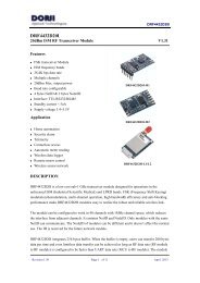
<strong>DRF4432D20</strong><br />
Users can configure the parameters (frequency, data rate, output power, etc.) of RF modules<br />
by PC or MCU.<br />
� BY PC. The interface of <strong>DRF4432D20</strong> is UART/TTL. If connecting it to PC, users need<br />
to use a TTL-to-RS232 level converter to transform the different levels. <strong>Dorji</strong> Applied<br />
Technologies also provides converter board for configuration.<br />
Firstly users need to insert module into converter board and connect converter board to<br />
PC by cable, then open DORJI RF software. After that the status column of tool should<br />
display “Found Device”. Users then can read/write the module. For more details, please<br />
check the operation manuals of converter boards on accessory page.<br />
Figure 1: DORJI RF Tool<br />
� BY MCU. The module can work normally after powering on for 50ms (T1) or more.<br />
When configuring the module, users need to switch the module to sleep mode (EN pin is<br />
high or floating) and monitor AUX pin. When AUX pin is high (no Receive or Transmit),<br />
the module will enter sleep mode in which the module can be configured after 20us (T2).<br />
When command is input to RXD pin, the module will be evoked. No matter what status of<br />
UART interface, the module will use 9600 bps (data rate) and no parity check as default<br />
format to communicate.<br />
Revision 1.40 Page 4 of 9 Jun. 2012