DRA808M - Dorji
DRA808M - Dorji
DRA808M - Dorji
- No tags were found...

Create successful ePaper yourself
Turn your PDF publications into a flip-book with our unique Google optimized e-Paper software.
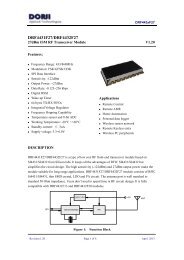
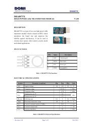
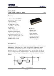
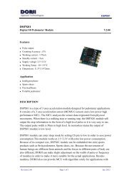
<strong>DRA808M</strong><strong>DRA808M</strong>30dBm Wireless Voice Transceiver Module V1.00Features:• Frequency Range: 400~470MHz• Tx/Rx frequency independent• Channel space: 12.5/25KHz• Configurable multi-channels• Sensitivity: -122dBm• Output power: +27/30dBm• 38 CTCSS codes• 6 volume levels• 8 squelch levels• UART interface• Temperature: -20°C ~+60°C• TX current: 450/750mA• Supply voltage: 3.3~4.5VApplications• Portable walkie-talkie• Outdoor sports products• Audio monitor system• Building security systemDESCRIPTION<strong>DRA808M</strong> is a type of compact wireless voice transceiver module. It integrates high speedmicrocontroller, high performance wireless transceiver IC, high power PA, audio process andsquelching circuits. It provides standard UART interface which users can easily configureappropriate parameters for different applications. Users can easily construct a walkie-talkie systemby connecting microphone, audio PA and speaker.ANTH / LH / L PA Driver PA ANT SWBATPDGNDLDOCTC/CDCCODELNAFilterAF D/AAudio ONAF OUTAMPDSPRF TransceiverMIC A/DMIC_INPTTPTT RSSI UARTTXD RXDFigure 1:<strong>DRA808M</strong> Functional BlockRevision 1.10 Page 1 of 7 Sep. 2013
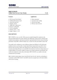
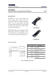
<strong>DRA808M</strong>PIN FUNCTIONS111218871Figure 2: <strong>DRA808M</strong> Pin LayoutPIN Name Function Description1 SQ Output Squelch detection.. Low Audio amplifier on2 TX_LED Output LED indication, High level output in TX mode3 AF_OUT Output Audio output pin.4 NC --- No connection5 PTT Input Tx/Rx control pin: LowTX; High RX6 PD Input Power saving control pin: Lowsleep mode; Highnormal mode7 H/L Input RF Power Selection: Low0.5W; floated1W8 VBAT Power Power supply9 GND Ground Ground (0V)10 GND Ground Ground (0V)11 NC --- No connection12 ANT --- Antenna port. 50 Ohm impedance13 NC --- No connection14 NC --- No connection15 NC --- No connection16 RXD Input UART input, TTL level17 TXD Output UART output, TTL level18 MIC_IN Input MIC inputTable 1: <strong>DRA808M</strong> Pin FunctionsELECTRICAL SPECIFICATIONSSymbol Parameter (condition) Min. Typ. Max. UnitsVCC Supply Voltage 3.3 4.0 4.5 VFreq Frequency range 400 470 MHzRevision 1.10 Page 2 of 7 Sep. 2013
<strong>DRA808M</strong>Temp Operating temperature range -20 25 60 °CIDD_RIDD_T ⑴Current in receive mode @ Audio amplifier on@ Audio amplifier off6055mAmACurrent in transmit mode @ Low Power Mode400 450@ High Power Mode700 750mAIDD_S Current in sleep mode 30 uACH_w Channel Space @ Narrow band@ Wide band12.525kHzkHzT_SW Tx/Rx switching time 20 mST_IN Module initializing time 300 500 mSZANT Antenna Impedance 50 OhmTable 2: <strong>DRA808M</strong> Electrical SpecificationsRECEIVE CHARACTERISTICSSymbol Parameter (condition) Min. Typ. Max. UnitsFreq Frequency range 400 470 MHzSen. Receiver sensitivity @12dB SINAD -120 -122 dBmSen_SQ Squelch function sensitivity -120 dBmSNR_R S/N in receive mode @ 1.5KHz Fdev. 45 50 dBACS Adjacent channel selection @ CH_w = 12.5 KHz 55 60 dBIR Inter-modulation rejection @ CH_w = 12.5 KHz 55 60 dBSPR Spurious emission rejection@ CH_w = 12.5 KHz 55 60 dBAF_ZOUT Audio output impedance 200 400 OhmAF_AMP Audio signal amplitude @1KHz 1 VppAF_RD Audio signal distortion @ 1KHz 1 3 %AF_FRFrequency response @300Hz@500Hz@1000Hz-30+40@2500Hz-10VCO_L VCO leak in receive mode @ LNA port -50 dBmTable 3: <strong>DRA808M</strong> Receive CharacteristicsRevision 1.10 Page 3 of 7 Sep. 2013
<strong>DRA808M</strong>TRANSMIT CHARACTERISTICSSymbol Parameter (condition) Min. Typ. Max. UnitsFreq Frequency range 400 470 MHzPoutOutput power @ Low Power Mode@ High Power Mode26292730dBmFdevMax. Frequency deviation @ Narrow band@ Wide band2.55KHzSen_MOD Modulation Sensitivity @1KHz at 2.5KHz Fdev. 8 12 16 mVAF_TD Audio modulation distortion@1KHz at 2.5KHz Fdev. 2 5 %MODModulation features @ 300Hz@ 500Hz@ 1000Hz-20 dB-5 -6 -9 dB0 dB@ 2500 Hz 3 6 9 dBSNR_T S/N in Transmit mode @1KHz at 2.5KHz Fdev. 38 40 45 dBFdev_C CTCSS frequency deviation 0.35 0.5 0.75 KHzCS Carrier suppression -60 dBcIM3 third-order intermodulation suppression -60 dBcACP Adjacent channel power @12.5KHz offset -60 dBcSE Spurious emission -36 dBcTable 4: <strong>DRA808M</strong> Transmit CharacteristicsABSOLUTE MAXIMUM RATINGSSymbol Parameter Min. Max. UnitsVCC Supply Voltage -3.3 5 VVIN Input voltage -0.3 VCC+0.3 VIIN Input current -10 10 mATST Storage temperature -40 90 °CTable 5: DRA808 Maximum RatingsPARAMETERS SETTINGSome parameters of <strong>DRA808M</strong> modules can be changed by following the commands in thissection, which provide flexibility for designers to optimize related parameters to achieve the bestperformance. <strong>DRA808M</strong> modules use standard UART interface to communicate withRevision 1.10 Page 4 of 7 Sep. 2013
<strong>DRA808M</strong>microcontrollers or other hosts. The default data format is: 8 data bits, 1 stop bit, no parity and9600 kbps data rate. All commands in ASCII codes start with “AT” and end with .1 Handshake CommandDescription: It is used to check if the module works normally. <strong>DRA808M</strong> module will sendback response information when it receives this command from the host. If the host doesn’treceive any response from module after three times of continuously sending this command, itwill restart the module.Format:AT+DMOCONNECT Module response: +DMOCONNECT: 0 2 Group Setting CommandDescription: This command is used to configure a group of module parameters.Format: AT+DMOSETGROUP=GBW,TFV,RFV,CXCSS,SQ Module response: +DMOCONNECT: X• GBW: Channels space. 012.5k; 125k• TFV: Transmit frequency. Range: 400.0000~470.0000MHz• RFV: Receive frequency. Range: 400.0000~470.0000MHz. The frequency should be the times of12.5KHz or 25KHz.• CXCSS: CTCSS value (00~38). 00 no code; 01~38 effective code• SQ: Squelch level (0~8). 0 monitor mode which can’t be used in scanning mode.• X: Configuration result. 0 succeeded; 1 data out of range.Example:Command: AT+DMOSETGROUP=0,415.1250,415.1250,12,4 Response: +DMOSETGROUP:03. Volume CommandDescription: This command is used to adjust the volume of module.Format:AT+DMOSETVOLUME=X Module response: + DMOSETVOLUME: X• X in command: Volume range (1~6).• X in response: 0 succeeded; 1failed.Revision 1.10 Page 5 of 7 Sep. 2013
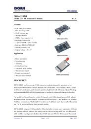
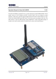
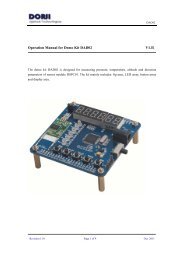
<strong>DRA808M</strong>TYPICAL APPLICATION CIRCUITFigure 3:<strong>DRA808M</strong> Application CircuitMECHANICAL DATAFigure 4:<strong>DRA808M</strong> Mechanical DimensionRevision 1.10 Page 6 of 7 Sep. 2013
<strong>DRA808M</strong><strong>Dorji</strong> Applied TechnologiesA division of <strong>Dorji</strong> Industrial Group Co., LtdAdd.: Xinchenhuayuan 2, Dalangnanlu, Longhua,Baoan district, Shenzhen, China 518109Tel: 0086-755-28156122Fax.: 0086-755-28156133Email: sales@dorji.comWeb: http://www.dorji.com<strong>Dorji</strong> Industrial Group Co., Ltd reserves the right tomake corrections, modifications, improvements andother changes to its products and services at any timeand to discontinue any product or service withoutnotice. Customers are expected to visit websites forgetting newest product information before placingorders.These products are not designed for use in life supportappliances, devices or other products wheremalfunction of these products might result in personalinjury. Customers using these products in suchapplications do so at their own risk and agree to fullyindemnify <strong>Dorji</strong> Industrial Group for any damagesresulting from improper use.Revision 1.10 Page 7 of 7 Sep. 2013