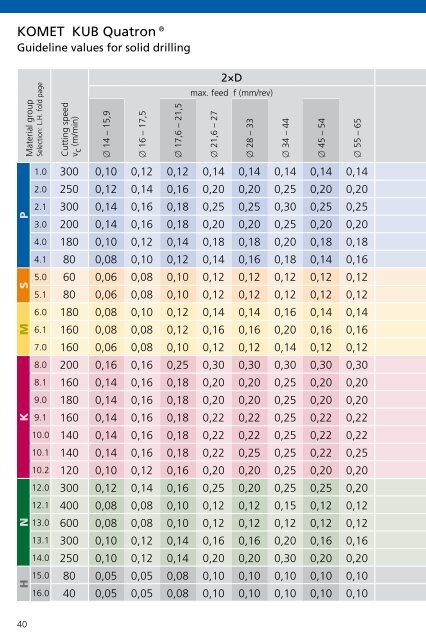
KOMET KUB Quatron® Guideline values for solid drilling Material group Selection: L.H. fold page P S M K 40 1.0 2.0 2.1 3.0 4.0 4.1 5.0 5.1 6.0 6.1 7.0 8.0 8.1 9.0 9.1 10.0 10.1 10.2 12.1 13.0 13.1 14.0 N 12.0 16.0 H 15.0 Cutting speed vc (m/min) x 14 – 15,9 x 16 – 17,5 x 17,6 – 21,5 2×D max. feed f (mm/rev) x 21,6 – 27 300 0,10 0,12 0,12 0,14 0,14 0,14 0,14 0,14 250 0,12 0,14 0,16 0,20 0,20 0,25 0,20 0,20 300 0,14 0,16 0,18 0,25 0,25 0,30 0,25 0,25 200 0,14 0,16 0,18 0,20 0,20 0,25 0,20 0,20 180 0,10 0,12 0,14 0,18 0,18 0,20 0,18 0,18 80 0,08 0,10 0,12 0,14 0,16 0,18 0,14 0,16 60 0,06 0,08 0,10 0,12 0,12 0,12 0,12 0,12 80 0,06 0,08 0,10 0,12 0,12 0,12 0,12 0,12 180 0,08 0,10 0,12 0,14 0,14 0,16 0,14 0,14 160 0,08 0,08 0,12 0,16 0,16 0,20 0,16 0,16 160 0,06 0,08 0,10 0,12 0,12 0,14 0,12 0,12 200 0,16 0,16 0,25 0,30 0,30 0,30 0,30 0,30 160 0,14 0,16 0,18 0,20 0,20 0,25 0,20 0,20 180 0,14 0,16 0,18 0,20 0,20 0,25 0,20 0,20 160 0,14 0,16 0,18 0,22 0,22 0,25 0,22 0,22 140 0,14 0,16 0,18 0,22 0,22 0,25 0,22 0,22 140 0,14 0,16 0,18 0,22 0,25 0,25 0,22 0,25 120 0,10 0,12 0,16 0,20 0,20 0,25 0,20 0,20 300 0,12 0,14 0,16 0,25 0,20 0,25 0,25 0,20 400 0,08 0,08 0,10 0,12 0,12 0,15 0,12 0,12 600 0,08 0,08 0,10 0,12 0,12 0,12 0,12 0,12 300 0,10 0,12 0,14 0,16 0,16 0,20 0,16 0,16 250 0,10 0,12 0,14 0,20 0,20 0,30 0,20 0,20 80 0,05 0,05 0,08 0,10 0,10 0,10 0,10 0,10 40 0,05 0,05 0,08 0,10 0,10 0,10 0,10 0,10 x 28 – 33 x 34 – 44 x 45 – 54 x 55 – 65
x 14 – 15,9 x 16 – 17,5 x 17,6 – 21,5 3×D max. feed f (mm/rev) x 21,6 – 27 KOMET KUB Quatron® Guideline values for solid drilling 0,10 0,12 0,12 0,14 0,14 0,14 0,14 0,14 0,12 0,14 0,16 0,20 0,20 0,25 0,20 0,20 0,14 0,16 0,18 0,25 0,25 0,30 0,25 0,25 0,14 0,16 0,18 0,20 0,20 0,25 0,20 0,20 0,10 0,12 0,14 0,18 0,18 0,20 0,18 0,18 0,08 0,10 0,12 0,14 0,14 0,06 0,08 0,10 0,12 0,12 0,12 0,12 0,12 0,06 0,08 0,10 0,12 0,12 0,12 0,12 0,12 0,08 0,10 0,12 0,14 0,14 0,16 0,14 0,14 0,08 0,08 0,12 0,16 0,16 0,20 0,16 0,16 0,06 0,08 0,10 0,12 0,12 0,14 0,12 0,12 0,16 0,16 0,25 0,30 0,30 0,30 0,30 0,30 0,14 0,16 0,18 0,20 0,20 0,25 0,20 0,20 0,14 0,16 0,18 0,20 0,20 0,25 0,20 0,20 0,14 0,16 0,18 0,22 0,22 0,25 0,22 0,22 0,14 0,16 0,18 0,22 0,22 0,25 0,22 0,22 0,14 0,16 0,18 0,22 0,25 0,25 0,22 0,25 0,10 0,12 0,16 0,20 0,20 0,25 0,20 0,20 0,12 0,14 0,16 0,25 0,20 0,25 0,25 0,20 0,08 0,08 0,10 0,12 0,12 0,15 0,12 0,12 0,08 0,08 0,10 0,12 0,12 0,12 0,12 0,12 0,10 0,12 0,14 0,16 0,16 0,20 0,16 0,16 0,10 0,12 0,14 0,20 0,20 0,30 0,20 0,20 0,05 0,05 0,08 0,10 0,10 0,10 0,10 0,10 0,05 0,05 0,08 0,10 0,10 0,10 0,10 0,10 Important: For more application details and safety notes see E 74-75! x 28 – 33 x 34 – 44 x 45 – 54 x 55 – 65 41
- Page 1 and 2: KOMGUIDE - Technical Manual Drillin
- Page 3 and 4: 1.1 # 400 # 120 Material magnetic s
- Page 5 and 6: Index General information Formulae,
- Page 7 and 8: Explanation Tolerance zone The axis
- Page 9 and 10: +150 +100 +50 0 -50 -100 +100 +50 0
- Page 11 and 12: Surface finish class N12 50 160 N11
- Page 13 and 14: Tools from the KOMET GROUP can also
- Page 15 and 16: International Material Classificati
- Page 17 and 18: International Material Classificati
- Page 19 and 20: AFNOR SS UNI UNE JIS Z100CDV5 2260
- Page 21 and 22: International Material Classificati
- Page 23 and 24: General Formulae D × p × n vc = 1
- Page 25 and 26: P S M K Material group 1.0 2.0 500-
- Page 27 and 28: Torque M d in Nm Torque M d Cutting
- Page 29 and 30: KOMET KUB Quatron® KOMET KUB Pentr
- Page 31 and 32: From experience: 1. Pilot hole Dril
- Page 33 and 34: KOMET KUB® Drillmax, KUB® Drillma
- Page 35 and 36: Material group Selection: L.H. fold
- Page 37 and 38: Material group Selection: R.H. fold
- Page 39 and 40: Material group Selection: R.H. fold
- Page 41: P S M K N H P S M K N H P S M K N H
- Page 45 and 46: KOMET KUB Quatron® Guideline value
- Page 47 and 48: P S M K N H P S M K N H P S M K N H
- Page 49 and 50: 4×D Material group Selection: L.H.
- Page 51 and 52: 4×D 4×D Feed f (mm/rev) KOMET KUB
- Page 53 and 54: 5×D Material group Selection: L.H.
- Page 55 and 56: 5×D 5×D Feed f (mm/rev) KOMET KUB
- Page 57 and 58: P S M K N H P S M K N H P S M K N H
- Page 59 and 60: x 14 - 16,9 x 17 - 19,9 KOMET KUB T
- Page 61 and 62: P40 from 20 KOMET KUB Trigon®, KUB
- Page 63 and 64: Material group Selection: L.H. fold
- Page 65 and 66: Material group Selection: L.H. fold
- Page 67 and 68: P S M K N H P S M K N H P S M K N H
- Page 69 and 70: KOMET KUB Centron®, KUB® V464 Gui
- Page 71 and 72: Inserts suggested for KUB® and KUB
- Page 73 and 74: P S M K N H P S M K N H P S M K N H
- Page 75 and 76: Z x Method 1: Determining the centr
- Page 77 and 78: Safety notes! KOMET® Usage and saf
- Page 79 and 80: � � � KOMET KUB® Drillmax, K
- Page 81 and 82: D 2 ±1 1-4 mm 9. Starting on a wel
- Page 83 and 84: 2×D KOMET KUB Quatron®, KUB Trigo
- Page 85 and 86: 3×D KOMET KUB Quatron®, KUB Trigo
- Page 87 and 88: 4×D 7. Starting on a groove or lar
- Page 89 and 90: � � � KOMET KUB Pentron® Tec
- Page 91 and 92: KOMET KUB Duon® Technical notes 7.
- Page 93 and 94:
KOMET KUB Centron® Technical notes
- Page 95 and 96:
Stationary use Rotating use KOMET K
- Page 97 and 98:
Rotating use Stationary use KOMET K
- Page 99 and 100:
KOMET KUB Duon® Problems � possi
- Page 101 and 102:
KUB Quatron® KUB Trigon® KUB Duon
- Page 103 and 104:
KOMET TwinKom® G01 E 102-103 KOMET
- Page 105 and 106:
Offset = 3 mm 100 - 80 d = 100 - +
- Page 107 and 108:
Guideline values for medium strengt
- Page 109 and 110:
R a 2 1,75 1,50 1,25 1,00 0,75 0,50
- Page 111 and 112:
KOMET TwinKom® Insert selection W0
- Page 113 and 114:
W29 10 a p = 1 W29 18 a p = 1,5 KOM
- Page 115 and 116:
Material group Selection: L.H. fold
- Page 117 and 118:
Material group Selection: L.H. fold
- Page 119 and 120:
KOMET TwinKom® Problems � possib
- Page 121 and 122:
KOMET TwinKom® Chip formation from
- Page 123 and 124:
KOMET MicroKom® hi.flex KOMET Micr
- Page 125 and 126:
Material group Selection: L.H. fold
- Page 127 and 128:
� MicroKom® M040 � MicroKom®
- Page 129 and 130:
Subject to length: diameter ratio L
- Page 131 and 132:
a p 4,0 3,5 3,0 2,5 2,0 1,5 1,0 0,7
- Page 133 and 134:
P25 M M K N BK BK CK P40 2710 8425
- Page 135 and 136:
KOMET® W30, W57 Chip formation fro
- Page 137 and 138:
ISO Codes for Inserts KOMET® ISO C
- Page 139 and 140:
Numerical Coding for Inserts W.. Pr
- Page 141 and 142:
Stress fracture caused by: • wron
- Page 143 and 144:
Thread milling tool Drill thread mi
- Page 145 and 146:
Tapping • Chip producing method
- Page 147 and 148:
Size MF - Metric fine thread JEL®
- Page 149 and 150:
Size NPT, NPTF - without using a re
- Page 151 and 152:
Material Steel Stainless steel Grey
- Page 153 and 154:
P H M K S N Surface uncoated Nom. x
- Page 155 and 156:
P H M K S N Surface uncoated Nom. x
- Page 157 and 158:
P H M K S N Surface Nom. x 1.1 1.2
- Page 159 and 160:
P H M K S N 1.1 1.2 1.3 1.4 1.5 1.6
- Page 161 and 162:
JEL® (Drill) Thread Milling CNC pr
- Page 163 and 164:
Formulae D × p × n vc = 1000 vc
- Page 165 and 166:
Cast aluminium • Can be carried o
- Page 167 and 168:
JEL® Drill Thread Milling Tool Pro
- Page 169 and 170:
Forming gap JEL® Roll Form Tap Pro
- Page 171 and 172:
No. of threads NOMINAL ACTUAL JEL®
- Page 173 and 174:
JEL® End mill cutter AL JEL® End
- Page 175 and 176:
JEL® Solid Carbide Milling Cutter
- Page 177 and 178:
JEL® Solid Carbide Milling Cutter
- Page 179 and 180:
Feed f z (mm/tooth) Kf 3 0,26 0,24
- Page 181 and 182:
Feed f z (mm/tooth) Kf p1-p5 0,40 0
- Page 183 and 184:
Finish milling v c finish = 1,5 ×
- Page 185 and 186:
JEL® PCD Guideline values for PCD
- Page 187 and 188:
Nom. x P H M K S N 1.1 1.2 1.3 1.4
- Page 189 and 190:
Inclined plunging Milling machining
- Page 191 and 192:
normal KOMET® Quatron hi.feed Guid
- Page 193 and 194:
DIHART® Solid carbide reamer DIHAR
- Page 195 and 196:
IT 5 - IT 6 IT 7 M IT 8 x 1,40 - 5,
- Page 197 and 198:
Adjusting: • Set the µm dial by
- Page 199 and 200:
Central coolant outlet Lateral cool
- Page 201 and 202:
Lobe (measuring tooth) M DIHART® C
- Page 203 and 204:
Measuring tooth A M DIHART® Duomax
- Page 205 and 206:
DIHART® Insert Reaming Assembly in
- Page 207 and 208:
6 5 � � 4 DIHART® MicroSet Sys
- Page 209 and 210:
DIHART DAH® 50 HS Simple handling
- Page 211 and 212:
HM DST TiN DBG-N min-max min-max mi
- Page 213 and 214:
Feed f z (mm/tooth) (with face cut,
- Page 215 and 216:
Geometry Flute form ASG0703 ASG0704
- Page 217 and 218:
Cutting materials DST HM Coatings T
- Page 219 and 220:
Notch wear Notch wear Built-up DIHA
- Page 221 and 222:
DIHART® Problems � possible caus
- Page 223 and 224:
Mark of measuring teeth • Drive p
- Page 225 and 226:
Outside Europe Egypt ZAHRANCO, ENGI
- Page 227 and 228:
Notes