- Page 1 and 2: KOMGUIDE - Technical Manual Drillin
- Page 3 and 4: 1.1 # 400 # 120 Material magnetic s
- Page 5 and 6: Index General information Formulae,
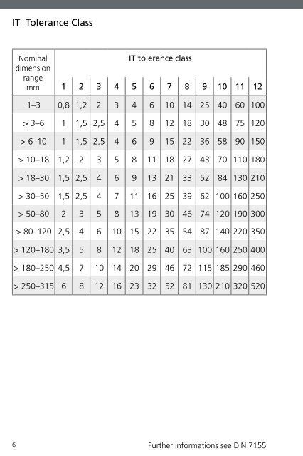
- Page 7: Explanation Tolerance zone The axis
- Page 11 and 12: Surface finish class N12 50 160 N11
- Page 13 and 14: Tools from the KOMET GROUP can also
- Page 15 and 16: International Material Classificati
- Page 17 and 18: International Material Classificati
- Page 19 and 20: AFNOR SS UNI UNE JIS Z100CDV5 2260
- Page 21 and 22: International Material Classificati
- Page 23 and 24: General Formulae D × p × n vc = 1
- Page 25 and 26: P S M K Material group 1.0 2.0 500-
- Page 27 and 28: Torque M d in Nm Torque M d Cutting
- Page 29 and 30: KOMET KUB Quatron® KOMET KUB Pentr
- Page 31 and 32: From experience: 1. Pilot hole Dril
- Page 33 and 34: KOMET KUB® Drillmax, KUB® Drillma
- Page 35 and 36: Material group Selection: L.H. fold
- Page 37 and 38: Material group Selection: R.H. fold
- Page 39 and 40: Material group Selection: R.H. fold
- Page 41 and 42: P S M K N H P S M K N H P S M K N H
- Page 43 and 44: x 14 - 15,9 x 16 - 17,5 x 17,6 - 21
- Page 45 and 46: KOMET KUB Quatron® Guideline value
- Page 47 and 48: P S M K N H P S M K N H P S M K N H
- Page 49 and 50: 4×D Material group Selection: L.H.
- Page 51 and 52: 4×D 4×D Feed f (mm/rev) KOMET KUB
- Page 53 and 54: 5×D Material group Selection: L.H.
- Page 55 and 56: 5×D 5×D Feed f (mm/rev) KOMET KUB
- Page 57 and 58: P S M K N H P S M K N H P S M K N H
- Page 59 and 60:
x 14 - 16,9 x 17 - 19,9 KOMET KUB T
- Page 61 and 62:
P40 from 20 KOMET KUB Trigon®, KUB
- Page 63 and 64:
Material group Selection: L.H. fold
- Page 65 and 66:
Material group Selection: L.H. fold
- Page 67 and 68:
P S M K N H P S M K N H P S M K N H
- Page 69 and 70:
KOMET KUB Centron®, KUB® V464 Gui
- Page 71 and 72:
Inserts suggested for KUB® and KUB
- Page 73 and 74:
P S M K N H P S M K N H P S M K N H
- Page 75 and 76:
Z x Method 1: Determining the centr
- Page 77 and 78:
Safety notes! KOMET® Usage and saf
- Page 79 and 80:
� � � KOMET KUB® Drillmax, K
- Page 81 and 82:
D 2 ±1 1-4 mm 9. Starting on a wel
- Page 83 and 84:
2×D KOMET KUB Quatron®, KUB Trigo
- Page 85 and 86:
3×D KOMET KUB Quatron®, KUB Trigo
- Page 87 and 88:
4×D 7. Starting on a groove or lar
- Page 89 and 90:
� � � KOMET KUB Pentron® Tec
- Page 91 and 92:
KOMET KUB Duon® Technical notes 7.
- Page 93 and 94:
KOMET KUB Centron® Technical notes
- Page 95 and 96:
Stationary use Rotating use KOMET K
- Page 97 and 98:
Rotating use Stationary use KOMET K
- Page 99 and 100:
KOMET KUB Duon® Problems � possi
- Page 101 and 102:
KUB Quatron® KUB Trigon® KUB Duon
- Page 103 and 104:
KOMET TwinKom® G01 E 102-103 KOMET
- Page 105 and 106:
Offset = 3 mm 100 - 80 d = 100 - +
- Page 107 and 108:
Guideline values for medium strengt
- Page 109 and 110:
R a 2 1,75 1,50 1,25 1,00 0,75 0,50
- Page 111 and 112:
KOMET TwinKom® Insert selection W0
- Page 113 and 114:
W29 10 a p = 1 W29 18 a p = 1,5 KOM
- Page 115 and 116:
Material group Selection: L.H. fold
- Page 117 and 118:
Material group Selection: L.H. fold
- Page 119 and 120:
KOMET TwinKom® Problems � possib
- Page 121 and 122:
KOMET TwinKom® Chip formation from
- Page 123 and 124:
KOMET MicroKom® hi.flex KOMET Micr
- Page 125 and 126:
Material group Selection: L.H. fold
- Page 127 and 128:
� MicroKom® M040 � MicroKom®
- Page 129 and 130:
Subject to length: diameter ratio L
- Page 131 and 132:
a p 4,0 3,5 3,0 2,5 2,0 1,5 1,0 0,7
- Page 133 and 134:
P25 M M K N BK BK CK P40 2710 8425
- Page 135 and 136:
KOMET® W30, W57 Chip formation fro
- Page 137 and 138:
ISO Codes for Inserts KOMET® ISO C
- Page 139 and 140:
Numerical Coding for Inserts W.. Pr
- Page 141 and 142:
Stress fracture caused by: • wron
- Page 143 and 144:
Thread milling tool Drill thread mi
- Page 145 and 146:
Tapping • Chip producing method
- Page 147 and 148:
Size MF - Metric fine thread JEL®
- Page 149 and 150:
Size NPT, NPTF - without using a re
- Page 151 and 152:
Material Steel Stainless steel Grey
- Page 153 and 154:
P H M K S N Surface uncoated Nom. x
- Page 155 and 156:
P H M K S N Surface uncoated Nom. x
- Page 157 and 158:
P H M K S N Surface Nom. x 1.1 1.2
- Page 159 and 160:
P H M K S N 1.1 1.2 1.3 1.4 1.5 1.6
- Page 161 and 162:
JEL® (Drill) Thread Milling CNC pr
- Page 163 and 164:
Formulae D × p × n vc = 1000 vc
- Page 165 and 166:
Cast aluminium • Can be carried o
- Page 167 and 168:
JEL® Drill Thread Milling Tool Pro
- Page 169 and 170:
Forming gap JEL® Roll Form Tap Pro
- Page 171 and 172:
No. of threads NOMINAL ACTUAL JEL®
- Page 173 and 174:
JEL® End mill cutter AL JEL® End
- Page 175 and 176:
JEL® Solid Carbide Milling Cutter
- Page 177 and 178:
JEL® Solid Carbide Milling Cutter
- Page 179 and 180:
Feed f z (mm/tooth) Kf 3 0,26 0,24
- Page 181 and 182:
Feed f z (mm/tooth) Kf p1-p5 0,40 0
- Page 183 and 184:
Finish milling v c finish = 1,5 ×
- Page 185 and 186:
JEL® PCD Guideline values for PCD
- Page 187 and 188:
Nom. x P H M K S N 1.1 1.2 1.3 1.4
- Page 189 and 190:
Inclined plunging Milling machining
- Page 191 and 192:
normal KOMET® Quatron hi.feed Guid
- Page 193 and 194:
DIHART® Solid carbide reamer DIHAR
- Page 195 and 196:
IT 5 - IT 6 IT 7 M IT 8 x 1,40 - 5,
- Page 197 and 198:
Adjusting: • Set the µm dial by
- Page 199 and 200:
Central coolant outlet Lateral cool
- Page 201 and 202:
Lobe (measuring tooth) M DIHART® C
- Page 203 and 204:
Measuring tooth A M DIHART® Duomax
- Page 205 and 206:
DIHART® Insert Reaming Assembly in
- Page 207 and 208:
6 5 � � 4 DIHART® MicroSet Sys
- Page 209 and 210:
DIHART DAH® 50 HS Simple handling
- Page 211 and 212:
HM DST TiN DBG-N min-max min-max mi
- Page 213 and 214:
Feed f z (mm/tooth) (with face cut,
- Page 215 and 216:
Geometry Flute form ASG0703 ASG0704
- Page 217 and 218:
Cutting materials DST HM Coatings T
- Page 219 and 220:
Notch wear Notch wear Built-up DIHA
- Page 221 and 222:
DIHART® Problems � possible caus
- Page 223 and 224:
Mark of measuring teeth • Drive p
- Page 225 and 226:
Outside Europe Egypt ZAHRANCO, ENGI
- Page 227 and 228:
Notes