seismic analysis as a tool for checking the structural system
seismic analysis as a tool for checking the structural system
seismic analysis as a tool for checking the structural system

You also want an ePaper? Increase the reach of your titles
YUMPU automatically turns print PDFs into web optimized ePapers that Google loves.
SEISMIC ANALYSIS AS A TOOL FOR CHECKING THE<br />
STRUCTURAL SYSTEM<br />
Autors:<br />
Doc. Ing. Milan SOKOL, PhD., SLOVAK UNIVERSITY OF TECHNOLOGY,<br />
DEPARTMENT OF STRUCTURAL MECHANICS, Radlinského 11, Bratislava, Slovakia,<br />
e-mail: milan.sokol@stuba.sk<br />
Ing. Katarína TVRDÁ, PhD., SLOVAK UNIVERSITY OF TECHNOLOGY,<br />
DEPARTMENT OF STRUCTURAL MECHANICS, Radlinského 11, Bratislava, Slovakia,<br />
e-mail: katarina.tvrda@stuba.sk<br />
Anotácia<br />
Na železobétonovej rámovej konštrukcii vystavenej vyššej úrovni seizmického zaťaženia boli<br />
počítané seizmické návrhové účinky a posudzované prierezy. Výpočet rotačnej kapacity<br />
prierezov dokázal, že pôvodná voľba triedy poddajnosti „nízka“ bol jedinou vhodnou<br />
alternatívou. Pokiaľ vychádzala odolnosť prierezov nižšia, ako seizmické účinky, návrh<br />
možných konštrukčných opatrení umožňoval len zmenu konštrukčného systému s pridaním<br />
ďalších stien.<br />
Annotation<br />
The frame R/C structure subjected to higher level of <strong>seismic</strong> effects w<strong>as</strong> analysed. The<br />
<strong>analysis</strong> of rotation capacity reserves h<strong>as</strong> proved, that initially chosen ductility cl<strong>as</strong>s “L” w<strong>as</strong><br />
only choice and <strong>for</strong> such type of structure <strong>the</strong>re is no possible to use higher ductility cl<strong>as</strong>s. If<br />
design values were not conservative, it means <strong>the</strong> resistance of cross section w<strong>as</strong> not<br />
sufficient, <strong>the</strong> only change of <strong>the</strong> <strong>structural</strong> <strong>system</strong>, e.g. design of additional walls, w<strong>as</strong> an<br />
appropriate solution.<br />
Introduction<br />
A frame building situated in a high vulnerable <strong>seismic</strong> area is analysed. The <strong>seismic</strong> effects<br />
are calculated according to Eurocode ENV 1998:1997. The <strong>structural</strong> <strong>system</strong> per<strong>for</strong>mance is<br />
checked. Rotation capacity of cross sections is discussed.<br />
Description of <strong>the</strong> building<br />
The layout of <strong>the</strong> building consists of a ground floor and a first floor with a b<strong>as</strong>ement. The<br />
rein<strong>for</strong>ced concrete structure consists of a foundation slab, columns, beams, slab floors and<br />
walls. The unusual <strong>structural</strong> detail of this structure is a heavy roof slab leading to <strong>the</strong> high<br />
m<strong>as</strong>ses in top level.<br />
The longitudinal section of building is shown on Fig.1 and <strong>the</strong> transversal section on Fig.2.<br />
Foundation is on a foundation slab. Thickness of this slab is 0,5m. The footprint dimensions<br />
are 29x18 m and <strong>the</strong> slab is spreaded by 500mm outside <strong>the</strong> perimeter column axes grid. On<br />
<strong>the</strong> perimeter of <strong>the</strong> b<strong>as</strong>ement <strong>the</strong>re is a rein<strong>for</strong>ced concrete wall 300mm thick.<br />
Columns are located on a 5.5 x 5.5m grid (i.e. 5x5.5m spans in longitudinal direction and<br />
3x5.5m in transversal direction). The columns are 450x450mm rein<strong>for</strong>ced with 12φ25 bars.<br />
The corner columns are 500x500mm rein<strong>for</strong>ced with 16φ25 bars. The rein<strong>for</strong>cing bars are<br />
distributed uni<strong>for</strong>mly along <strong>the</strong> perimeter of <strong>the</strong> cross-section.<br />
ANSYS konference 2008<br />
16. ANSYS FEM Users‘ Meeting & 14. ANSYS CFD Users’ Meeting<br />
Luhačovice 5. - 7. listopadu 2008<br />
- 1 -
3125 3200<br />
3250<br />
5500 5500 5500 5500 5500<br />
5500 5500 5500<br />
Fig.1 Longitudinal section<br />
Fig.2 Transversal section<br />
The columns are 450x450mm rein<strong>for</strong>ced with 12φ25 bars. The corner columns are<br />
500x500mm rein<strong>for</strong>ced with 16φ25 bars. The rein<strong>for</strong>cing bars are distributed uni<strong>for</strong>mly along<br />
<strong>the</strong> perimeter of <strong>the</strong> cross-section.<br />
Ground-floor<br />
Thickness of <strong>the</strong> ground-floor slab is 200mm. The columns are 450x450mm rein<strong>for</strong>ced with<br />
12φ25 bars. The corner columns are 500x500mm rein<strong>for</strong>ced with 16φ25 bars. Beams are<br />
400x650mm (450mm+200mm slab), rein<strong>for</strong>ced by 12φ25 bars uni<strong>for</strong>mly distributed along <strong>the</strong><br />
perimeter of <strong>the</strong> cross-section.<br />
First-floor<br />
Thickness of <strong>the</strong> first-floor slab is 200mm. The columns are 450x450mm rein<strong>for</strong>ced with<br />
12φ25 bars. The corner columns are 500x500mm rein<strong>for</strong>ced with 16φ25 bars. Beams are<br />
400x650mm (450mm+200mm slab).<br />
Roof<br />
The roof is located over one part of <strong>the</strong> building, 3x5.5m spans in longitudinal direction and<br />
3x5.5m in transversal direction, with a 1200mm overhang along <strong>the</strong> perimeter. The thickness<br />
of <strong>the</strong> roof slab is 200mm. On <strong>the</strong> roof is an additional 150mm thick concrete covering slab.<br />
Beams are 400x650mm (450mm+200mm slab).<br />
Structural model<br />
The building w<strong>as</strong> modelled <strong>as</strong> a 3D <strong>system</strong> consisting of beams, columns, slabs and walls<br />
(Fig.3 and Fig.4). The material concrete C35/45 with characteristic compression strength<br />
35MPa and rein<strong>for</strong>cing steel S220 are used.<br />
In order to provide sufficient <strong>seismic</strong> resistance R/C shear walls of 200mm thickness are<br />
arranged in both X and Z horizontal directions (Fig.4).The walls and floors were modelled<br />
with shell elements, <strong>the</strong> columns and beams <strong>as</strong> beam elements.<br />
The el<strong>as</strong>tic foundation stiffness (EFS), defined <strong>as</strong> <strong>the</strong> pressure producing a unit normal<br />
deflection of <strong>the</strong> foundation, is considered. The el<strong>as</strong>tic foundation capability is <strong>as</strong>sumed <strong>for</strong><br />
foundation slab (EFS=50MPa/m) <strong>as</strong> well <strong>as</strong> <strong>for</strong> walls under <strong>the</strong> ground level<br />
(EFS=25MPa/m).<br />
ANSYS konference 2008<br />
16. ANSYS FEM Users‘ Meeting & 14. ANSYS CFD Users’ Meeting<br />
Luhačovice 5. - 7. listopadu 2008<br />
- 2 -
Fig.3 Structural 3D model<br />
Fig.4 R/C shear walls<br />
Static Loads<br />
B<strong>as</strong>ement<br />
Dead load Self-weight of foundation slab 500 mm 12.5 kN/m 2<br />
Self-weight of concrete wall 300mm<br />
19.5 kN/m<br />
Ground-floor<br />
Dead load Self-weight of slab 200 mm 5 kN/m 2<br />
Additional self-weight 2.5 kN/m 2<br />
Self-weight of m<strong>as</strong>onry partition walls 5.6 kN/m 2<br />
First-floor<br />
Dead load Self-weight of slab 200 mm 5 kN/m 2<br />
Additional self-weight 2.5 kN/m 2<br />
Self-weight of m<strong>as</strong>onry partition walls 4.9 kN/m 2<br />
Roof<br />
Dead load Self-weight of slab 200 mm 5 kN/m 2<br />
Additional self-weight of concrete cover 3.75 kN/m 2<br />
Seismic load<br />
The site ground acceleration is quite high reaching <strong>the</strong> value of a g =3.2ms -2 . The soil<br />
parameters are similar to <strong>the</strong> soil cl<strong>as</strong>s B (ENV1998). It is <strong>as</strong>sumed a „Low“-ductile structure<br />
and <strong>the</strong>n <strong>the</strong> calculation of behaviour factor is taken according to (ENV 1998-1-3). Choice of<br />
a „Low“-ductile structure is due to <strong>the</strong> fact, that <strong>the</strong> cross-sectional rein<strong>for</strong>cement does not<br />
allow adequate rotational capacity.<br />
q 0 =5 <strong>for</strong> R/C frame structure,<br />
k D =0.5 - ductility cl<strong>as</strong>s factor (DC „L“),<br />
k R =0.8 - <strong>structural</strong> irregularity factor,<br />
q=q 0 k D k R =2.<br />
Because ductility cl<strong>as</strong>s “L” w<strong>as</strong> chosen, <strong>the</strong> m<strong>as</strong>onry walls (thickness 400mm) are not taken<br />
into account <strong>as</strong> <strong>structural</strong> elements. In spite of this, <strong>the</strong> m<strong>as</strong>onry walls should be furnished<br />
with a provision to protect <strong>the</strong>m against falling out of <strong>the</strong> R/C frame during <strong>seismic</strong> design<br />
situation. The inel<strong>as</strong>tic (q=2) design response spectrum, shown on Fig.5, is <strong>as</strong>sumed.<br />
ANSYS konference 2008<br />
16. ANSYS FEM Users‘ Meeting & 14. ANSYS CFD Users’ Meeting<br />
Luhačovice 5. - 7. listopadu 2008<br />
- 3 -
Fig.5 Inel<strong>as</strong>tic design response spectrum (q=2)<br />
Seismic effects<br />
Seismic effects are calculated on <strong>the</strong> 3D model. Accidental eccentricity<br />
e a =0.05L =1.375m<br />
is <strong>as</strong>sumed in such a way, that <strong>the</strong> centre of gravity of distributed m<strong>as</strong>ses of all loads on <strong>the</strong><br />
deck is shifted in –x direction by <strong>the</strong> value e a . The <strong>seismic</strong> effects are calculated in<br />
combination with dead load. The effects in all three directions are combined toge<strong>the</strong>r using all<br />
combinations of <strong>the</strong> following loads: dead load + <strong>seismic</strong> effects in one direction with<br />
magnitude 100% and <strong>seismic</strong> effects in ano<strong>the</strong>r two directions with magnitude 30%. Finally<br />
<strong>the</strong> envelope of all <strong>the</strong>se combinations is considered.<br />
First eigenfrequencies are shown in Fig.6. It is seen that <strong>the</strong> structure is irregular and <strong>the</strong><br />
torsion and bending modes are coupled, so <strong>the</strong> 3D modelling is necessary.<br />
Seismic displacements are shown on Fig.7.<br />
Fig.6 Eigenfrequencies [Hz]<br />
ANSYS konference 2008<br />
16. ANSYS FEM Users‘ Meeting & 14. ANSYS CFD Users’ Meeting<br />
Luhačovice 5. - 7. listopadu 2008<br />
- 4 -
z<br />
x<br />
ux [mm]<br />
uz [mm]<br />
Fig.7 Seismic displacements<br />
Beam bending moments especially in rein<strong>for</strong>cing beams of <strong>the</strong> slabs are shown on Fig8.<br />
B<strong>as</strong>ement Ground floor 1 st floor<br />
y 0 z 0<br />
M y0<br />
[Nm]<br />
M z0<br />
[Nm]<br />
N [N]<br />
Fig.8 Bending moments in rein<strong>for</strong>cing beams of <strong>the</strong> slabs<br />
ANSYS konference 2008<br />
16. ANSYS FEM Users‘ Meeting & 14. ANSYS CFD Users’ Meeting<br />
Luhačovice 5. - 7. listopadu 2008<br />
- 5 -
Column bending moments and normal <strong>for</strong>ces are shown on Fig.9. All values are in local<br />
coordinate <strong>system</strong>.<br />
x 0<br />
y 0<br />
Bending moments m x0 [kNm/m]<br />
Bending moments m y0 [kNm/m]<br />
-234<br />
-183<br />
y 0<br />
z 0<br />
173<br />
224<br />
Mz 0 [kNm]<br />
-194<br />
-151<br />
151<br />
194<br />
-1710<br />
-1490<br />
71<br />
294<br />
My 0 [kNm]<br />
N [kN]<br />
Fig.9 Column bending moments and normal <strong>for</strong>ces, corner’s columns 500x500mm<br />
Membrane <strong>for</strong>ces and beam bending moment on shear walls 200mms are shown on Fig.10.<br />
Stresses on shear walls 200mm are on Fig.11.<br />
y 0<br />
x 0<br />
Membrane <strong>for</strong>ces t x0 [kN/m]<br />
Membrane <strong>for</strong>ces t y0 [kN/m]<br />
Fig.10 Beam bending moments and membrane <strong>for</strong>ces<br />
ANSYS konference 2008<br />
16. ANSYS FEM Users‘ Meeting & 14. ANSYS CFD Users’ Meeting<br />
Luhačovice 5. - 7. listopadu 2008<br />
- 6 -
z<br />
y<br />
x<br />
Stresses σ x [MPa] Stresses σ y [MPa] Stresses τ xy [MPa]<br />
Fig.11 Stresses on shear walls<br />
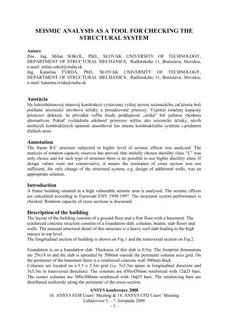
Cross-section rotation capacity<br />
The prescribed minimum rotation capacity (CCDF) <strong>for</strong> column - ductile cl<strong>as</strong>s „L“ is μ 5.<br />
No. of Steel<br />
bars<br />
Steel bar area<br />
Young'<br />
modulus Steel Concrete<br />
Design bending<br />
moment<br />
ohybova pruzna<br />
unosnost po<br />
odpadnuti krycej<br />
vrstvy<br />
5 C35/45<br />
H B d1 (cover) Φs As Es fyk fck Msd Mu q<br />
[mm] [mm] [mm] [mm] [mm2] [MPa] [MPa] [MPa] [kNm] [kNm]<br />
500 500 25 25 2454,4 200000 220 35 454,0 227,0 2<br />
1 / r<br />
=<br />
d [mm] 462,5 vyska od horneho okraja po os vystuze<br />
xlim [mm] 351,90 Hranica pruzneho pretvorenia Medzny moment zo seizmického výpo<br />
ξsy 0,7609 pre hodnotu q= 2<br />
εsy,k 0,0011<br />
Ns [N] 539961<br />
xcu' [mm] 34,283 vyska tlaceneho betonu po odpadnuti krytia d0[mm]= 420 rameno vnutornych sil po odpadnuti kryt<br />
xcu [mm] 59,283 suradnica neutralnej osi po odpadnuti krytia<br />
ξcu 0,1282<br />
ε<br />
εcu 0,0035 cu( 1−ξsy)<br />
= 5,94 concrete failure<br />
Tecenie vystuze<br />
Nsd [N] 1079922<br />
xsu'd [mm] 68,567 vyska tlaceneho beton μ1/r= min = 5,01<br />
xsu [mm] 93,567 suradnica neutralnej o<br />
ξsu 0,2023<br />
ε su ,k (1 − ξ sy )<br />
εsu,k 0,0201<br />
ε sy ,k (1 − ξ cu )<br />
= 5,01 steet failure<br />
ε<br />
sy,<br />
k<br />
ξ<br />
cu<br />
ξ cu =(x cu +d 1 )/d<br />
ξ sy =x lim /d<br />
σ b<br />
ε cu =-0,0035<br />
concrete<br />
Tear off cover<br />
ε c<br />
d<br />
d 1<br />
H<br />
B<br />
steel<br />
x<br />
ε su,k<br />
x lim<br />
d 1<br />
x cu ‘<br />
ε sy,k =f yk /E s<br />
σ s<br />
x cu<br />
ε s<br />
Fig. 12 Cross section 500x500mm rotation capacity <strong>analysis</strong><br />
ANSYS konference 2008<br />
16. ANSYS FEM Users‘ Meeting & 14. ANSYS CFD Users’ Meeting<br />
Luhačovice 5. - 7. listopadu 2008<br />
- 7 -
The rotation capacity CCDF is calculated <strong>as</strong>suming, that f y,k is not greater than 220MPa and<br />
concrete C35/45 is used. Although many parameters of cross section were changed, e.g.<br />
concrete material characteristics, cross section geometry, steel rein<strong>for</strong>cement parameters, <strong>the</strong><br />
rotation capacity does not incre<strong>as</strong>e significantly over <strong>the</strong> value 5. So <strong>the</strong> re<strong>as</strong>onable<br />
characteristics <strong>for</strong> this <strong>analysis</strong> were taken into account finally (Fig. 12).<br />
The <strong>analysis</strong> of rotation capacity reserves h<strong>as</strong> proved, that initially chosen ductility cl<strong>as</strong>s “L”<br />
w<strong>as</strong> only choice and <strong>for</strong> such type of structure <strong>the</strong>re is no possible to use higher ductility<br />
cl<strong>as</strong>s. If design values were not conservative, it means <strong>the</strong> resistance of cross section w<strong>as</strong> not<br />
sufficient, only change of <strong>the</strong> <strong>structural</strong> <strong>system</strong>, e.g. design of additional walls, is necessary.<br />
CONCLUSIONS<br />
Due to <strong>the</strong> fact that <strong>the</strong> considered site ground acceleration is quite high a g =3.2ms -2 and <strong>the</strong><br />
building h<strong>as</strong> a large m<strong>as</strong>s from an additional concrete layer situated on <strong>the</strong> roof, it w<strong>as</strong><br />
necessary to make some changes to <strong>the</strong> original design of <strong>the</strong> building. These changes can be<br />
summarised in <strong>the</strong> following:<br />
• The material w<strong>as</strong> changed to concrete C35/45 and rein<strong>for</strong>cing steel S220.<br />
• The cross-section of 400x400mm columns w<strong>as</strong> changed to 450x450mm.<br />
• The rein<strong>for</strong>cement of <strong>the</strong> members w<strong>as</strong> streng<strong>the</strong>ned. The columns 450x450mm were<br />
rein<strong>for</strong>ced with 12φ25 bars, <strong>the</strong> columns 500x500mm with 16φ25 bars, <strong>the</strong> beams<br />
400x650mm with 12φ25, all bars are uni<strong>for</strong>mly distributed along <strong>the</strong> perimeter of <strong>the</strong><br />
cross-section.<br />
• Rein<strong>for</strong>cing <strong>seismic</strong> resistance R/C shear walls of 200mm thickness were arranged in<br />
both transversal and longitudinal directions.<br />
In spite of this, <strong>the</strong> following results were obtained:<br />
• The beams in <strong>the</strong> ground-floor do not fulfil <strong>the</strong> design criteria <strong>for</strong> <strong>the</strong> moment<br />
resistance and <strong>the</strong> rotation capacity at <strong>the</strong> same time. When <strong>the</strong> rein<strong>for</strong>cement would<br />
be enlarged, <strong>the</strong>n <strong>the</strong> rotation capacity will be lower than 5 <strong>for</strong> DC”L” and <strong>the</strong><br />
behaviour factor q=2 can not be used. It means, that larger design spectrum values<br />
should be used, up to a value q=1, which means a 100% incre<strong>as</strong>e of <strong>seismic</strong> load.<br />
• The columns have no reserve <strong>for</strong> <strong>the</strong> bending in both directions.<br />
There<strong>for</strong>e a change of <strong>the</strong> <strong>structural</strong> <strong>system</strong> to a wall <strong>system</strong> or to a combined frame-wall<br />
<strong>system</strong> w<strong>as</strong> proposed.<br />
ACKNOWLEDGEMENT<br />
We kindly acknowledge <strong>the</strong> research program nr. 1/0573/08 granted by <strong>the</strong> Scientific Grant<br />
Agency of <strong>the</strong> Slovak Ministry of Education.<br />
REFERENCES:<br />
[1] ENV 1998. Design Provisions <strong>for</strong> Earthquake Resistance of Structures, Brussels, 1995.<br />
[2] FLESCH, R. & SOKOL, M.: Earthquake-resistant-design of high-rise-buildings using<br />
different <strong>structural</strong> models and methods. In: 11 th WCEE, Acapulco 1996. Paper 640<br />
(CD).<br />
[3] KOHNKE, P.C: Ansys, Eng. System, Theoret. Manual, Swanson Analysis System. 1989.<br />
[4] MESKOURIS. K. et al.: Seismic motion damage potential <strong>for</strong> R/C wall stiffened<br />
buildings. In Fajfar, P. & Krawinkler, H., Nonlinear Seismic Analysis and Design of RC<br />
Buildings; Proc. int. Conf., Bled, July 1992. London-Elsevier. 125-136. 1992.<br />
ANSYS konference 2008<br />
16. ANSYS FEM Users‘ Meeting & 14. ANSYS CFD Users’ Meeting<br />
Luhačovice 5. - 7. listopadu 2008<br />
- 8 -