seismic analysis as a tool for checking the structural system
seismic analysis as a tool for checking the structural system
seismic analysis as a tool for checking the structural system

Create successful ePaper yourself
Turn your PDF publications into a flip-book with our unique Google optimized e-Paper software.
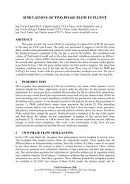
3125 3200<br />
3250<br />
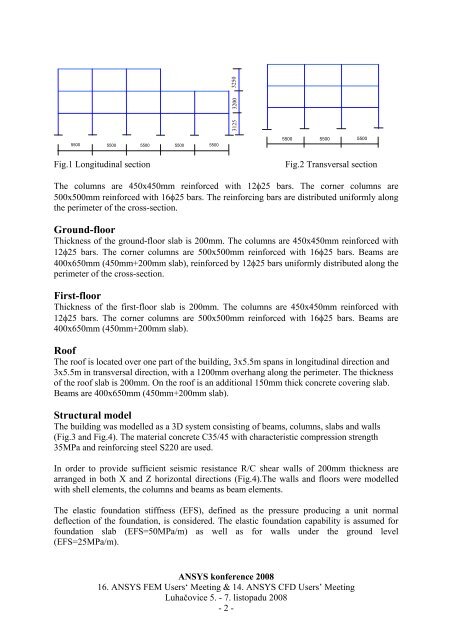
5500 5500 5500 5500 5500<br />
5500 5500 5500<br />
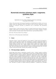
Fig.1 Longitudinal section<br />
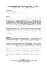
Fig.2 Transversal section<br />
The columns are 450x450mm rein<strong>for</strong>ced with 12φ25 bars. The corner columns are<br />
500x500mm rein<strong>for</strong>ced with 16φ25 bars. The rein<strong>for</strong>cing bars are distributed uni<strong>for</strong>mly along<br />
<strong>the</strong> perimeter of <strong>the</strong> cross-section.<br />
Ground-floor<br />
Thickness of <strong>the</strong> ground-floor slab is 200mm. The columns are 450x450mm rein<strong>for</strong>ced with<br />
12φ25 bars. The corner columns are 500x500mm rein<strong>for</strong>ced with 16φ25 bars. Beams are<br />
400x650mm (450mm+200mm slab), rein<strong>for</strong>ced by 12φ25 bars uni<strong>for</strong>mly distributed along <strong>the</strong><br />
perimeter of <strong>the</strong> cross-section.<br />
First-floor<br />
Thickness of <strong>the</strong> first-floor slab is 200mm. The columns are 450x450mm rein<strong>for</strong>ced with<br />
12φ25 bars. The corner columns are 500x500mm rein<strong>for</strong>ced with 16φ25 bars. Beams are<br />
400x650mm (450mm+200mm slab).<br />
Roof<br />
The roof is located over one part of <strong>the</strong> building, 3x5.5m spans in longitudinal direction and<br />
3x5.5m in transversal direction, with a 1200mm overhang along <strong>the</strong> perimeter. The thickness<br />
of <strong>the</strong> roof slab is 200mm. On <strong>the</strong> roof is an additional 150mm thick concrete covering slab.<br />
Beams are 400x650mm (450mm+200mm slab).<br />
Structural model<br />
The building w<strong>as</strong> modelled <strong>as</strong> a 3D <strong>system</strong> consisting of beams, columns, slabs and walls<br />
(Fig.3 and Fig.4). The material concrete C35/45 with characteristic compression strength<br />
35MPa and rein<strong>for</strong>cing steel S220 are used.<br />
In order to provide sufficient <strong>seismic</strong> resistance R/C shear walls of 200mm thickness are<br />
arranged in both X and Z horizontal directions (Fig.4).The walls and floors were modelled<br />
with shell elements, <strong>the</strong> columns and beams <strong>as</strong> beam elements.<br />
The el<strong>as</strong>tic foundation stiffness (EFS), defined <strong>as</strong> <strong>the</strong> pressure producing a unit normal<br />
deflection of <strong>the</strong> foundation, is considered. The el<strong>as</strong>tic foundation capability is <strong>as</strong>sumed <strong>for</strong><br />
foundation slab (EFS=50MPa/m) <strong>as</strong> well <strong>as</strong> <strong>for</strong> walls under <strong>the</strong> ground level<br />
(EFS=25MPa/m).<br />
ANSYS konference 2008<br />
16. ANSYS FEM Users‘ Meeting & 14. ANSYS CFD Users’ Meeting<br />
Luhačovice 5. - 7. listopadu 2008<br />
- 2 -