seismic analysis as a tool for checking the structural system
seismic analysis as a tool for checking the structural system
seismic analysis as a tool for checking the structural system

Create successful ePaper yourself
Turn your PDF publications into a flip-book with our unique Google optimized e-Paper software.
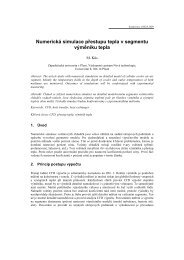
Fig.3 Structural 3D model<br />
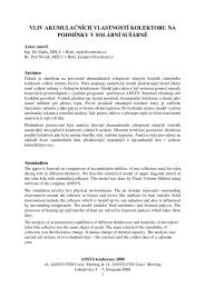
Fig.4 R/C shear walls<br />
Static Loads<br />
B<strong>as</strong>ement<br />
Dead load Self-weight of foundation slab 500 mm 12.5 kN/m 2<br />
Self-weight of concrete wall 300mm<br />
19.5 kN/m<br />
Ground-floor<br />
Dead load Self-weight of slab 200 mm 5 kN/m 2<br />
Additional self-weight 2.5 kN/m 2<br />
Self-weight of m<strong>as</strong>onry partition walls 5.6 kN/m 2<br />
First-floor<br />
Dead load Self-weight of slab 200 mm 5 kN/m 2<br />
Additional self-weight 2.5 kN/m 2<br />
Self-weight of m<strong>as</strong>onry partition walls 4.9 kN/m 2<br />
Roof<br />
Dead load Self-weight of slab 200 mm 5 kN/m 2<br />
Additional self-weight of concrete cover 3.75 kN/m 2<br />
Seismic load<br />
The site ground acceleration is quite high reaching <strong>the</strong> value of a g =3.2ms -2 . The soil<br />
parameters are similar to <strong>the</strong> soil cl<strong>as</strong>s B (ENV1998). It is <strong>as</strong>sumed a „Low“-ductile structure<br />
and <strong>the</strong>n <strong>the</strong> calculation of behaviour factor is taken according to (ENV 1998-1-3). Choice of<br />
a „Low“-ductile structure is due to <strong>the</strong> fact, that <strong>the</strong> cross-sectional rein<strong>for</strong>cement does not<br />
allow adequate rotational capacity.<br />
q 0 =5 <strong>for</strong> R/C frame structure,<br />
k D =0.5 - ductility cl<strong>as</strong>s factor (DC „L“),<br />
k R =0.8 - <strong>structural</strong> irregularity factor,<br />
q=q 0 k D k R =2.<br />
Because ductility cl<strong>as</strong>s “L” w<strong>as</strong> chosen, <strong>the</strong> m<strong>as</strong>onry walls (thickness 400mm) are not taken<br />
into account <strong>as</strong> <strong>structural</strong> elements. In spite of this, <strong>the</strong> m<strong>as</strong>onry walls should be furnished<br />
with a provision to protect <strong>the</strong>m against falling out of <strong>the</strong> R/C frame during <strong>seismic</strong> design<br />
situation. The inel<strong>as</strong>tic (q=2) design response spectrum, shown on Fig.5, is <strong>as</strong>sumed.<br />
ANSYS konference 2008<br />
16. ANSYS FEM Users‘ Meeting & 14. ANSYS CFD Users’ Meeting<br />
Luhačovice 5. - 7. listopadu 2008<br />
- 3 -