07.09. Schauberger - Repulsine - Redesign - Rotor
07.09. Schauberger - Repulsine - Redesign - Rotor
07.09. Schauberger - Repulsine - Redesign - Rotor

Create successful ePaper yourself
Turn your PDF publications into a flip-book with our unique Google optimized e-Paper software.
Alfred Evert 25. September 2008<br />
<strong>07.09.</strong> <strong>Schauberger</strong> - <strong>Repulsine</strong> - <strong>Redesign</strong><br />
Viktor <strong>Schauberger</strong><br />
At 25. September 2008, fifty years ago, Viktor <strong>Schauberger</strong> died. This ´<strong>Schauberger</strong>-Year´<br />
inspired to reconsider work of that great nature scientist and public interests increased.<br />
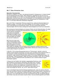
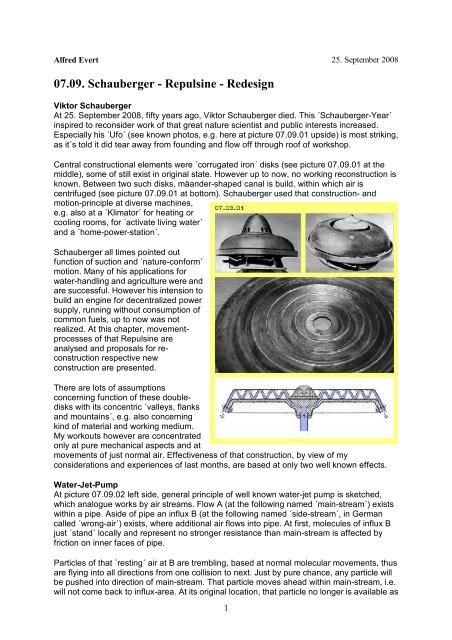
Especially his ´Ufo´ (see known photos, e.g. here at picture <strong>07.09.</strong>01 upside) is most striking,<br />
as it´s told it did tear away from founding and flow off through roof of workshop.<br />
Central constructional elements were ´corrugated iron´ disks (see picture <strong>07.09.</strong>01 at the<br />
middle), some of still exist in original state. However up to now, no working reconstruction is<br />
known. Between two such disks, mäander-shaped canal is build, within which air is<br />
centrifuged (see picture <strong>07.09.</strong>01 at bottom). <strong>Schauberger</strong> used that construction- and<br />
motion-principle at diverse machines,<br />
e.g. also at a ´Klimator´ for heating or<br />
cooling rooms, for ´activate living water´<br />
and a ´home-power-station´.<br />
<strong>Schauberger</strong> all times pointed out<br />
function of suction and ´nature-conform´<br />
motion. Many of his applications for<br />
water-handling and agriculture were and<br />
are successful. However his intension to<br />
build an engine for decentralized power<br />
supply, running without consumption of<br />
common fuels, up to now was not<br />
realized. At this chapter, movementprocesses<br />
of that <strong>Repulsine</strong> are<br />
analysed and proposals for reconstruction<br />
respective new<br />
construction are presented.<br />
There are lots of assumptions<br />
concerning function of these doubledisks<br />
with its concentric ´valleys, flanks<br />
and mountains´, e.g. also concerning<br />
kind of material and working medium.<br />
My workouts however are concentrated<br />
only at pure mechanical aspects and at<br />
movements of just normal air. Effectiveness of that construction, by view of my<br />
considerations and experiences of last months, are based at only two well known effects.<br />
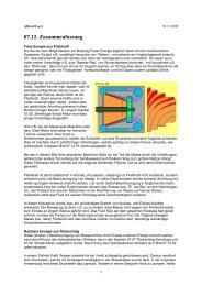
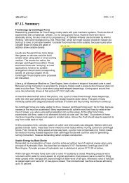
Water-Jet-Pump<br />
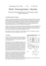
At picture <strong>07.09.</strong>02 left side, general principle of well known water-jet pump is sketched,<br />
which analogue works by air streams. Flow A (at the following named ´main-stream´) exists<br />
within a pipe. Aside of pipe an influx B (at the following named ´side-stream´, in German<br />
called ´wrong-air´) exists, where additional air flows into pipe. At first, molecules of influx B<br />
just ´stand´ locally and represent no stronger resistance than main-stream is affected by<br />
friction on inner faces of pipe.<br />
Particles of that ´resting´ air at B are trembling, based at normal molecular movements, thus<br />
are flying into all directions from one collision to next. Just by pure chance, any particle will<br />
be pushed into direction of main-stream. That particle moves ahead within main-stream, i.e.<br />
will not come back to influx-area. At its original location, that particle no longer is available as<br />
1
collision-partner, so is leaving some empty area there, into which following particles will fall.<br />
As many particles behave likely, flow C comes up within side-influx.<br />
That pipe downside at D shows wider cross-sectional surface than upside at A. Normally<br />
(see Bernoulli formula) such an extension results deceleration of flow and thus ´destroys´<br />
kinetic energy. Here however that wider cross-section if filled up by air mass of side-stream.<br />
All air-particles any time are moving by speed of about 500 m/s, also within a flow. When air<br />
is flowing, vectors of particle movements only are showing some more forward in flow´s<br />
direction, i.e. instead of ´local´ trembling these movements are wandering some forward. The<br />
faster a flow is, the more all movements show into likely directions. Finally at well structured<br />
flows, particles fly nearby ´parallel´ and come forward one nearby next. The stronger a mainstream<br />
is, the more side-stream will enter with less resistance. Up to sound-speed of about<br />
330 m/s, additional influx aside can follow original main-stream and is integrated without<br />
problems.<br />
The original stream practically works like<br />
´suction´, into which particles of additional<br />
stream ´disappear´. These pumps work really<br />
effective because mass throughput of sidestream<br />
practically is done by no additional<br />
energy-input. There is no acceleration of<br />
particles of side-stream (via power-input) nor<br />
deceleration of main-stream. Only some of these<br />
influx-particles (by given speed) fall into mainstream<br />
and move forward within - and other<br />
particles of influx area again fall behind into that<br />
direction (with their given speeds).<br />
So if an original main-stream exists, mass<br />
throughput can be strengthened by skilled merge<br />
of flows, where static pressure of side influx<br />
partly is transferred into dynamic pressure of structured flow. So kinetic energy of that sideflow<br />
is usable e.g. for generating mechanical turning momentum.<br />
Laval-Nozzle<br />
Second effect used here is based on function of Laval-nozzles, where flows of (ultra-) soundspeed<br />
are generated. At picture 09.09.02 right side, schematic is sketched a longitudinal<br />
cross-sectional view of Laval-nozzle. Motion-processes of such nozzles in details are<br />
described at chapter ´06.03. Ultra-Sound-Engine´ and once again at chapter ´07.06. Wind-<br />
Tower-Electric-Generator´. At the following thus important function of Laval-nozzles is<br />
mentioned only in brief.<br />
Within a pipe E (grey) a flow must exist e.g. by 10 to 30 m/s, so corresponding to strong-wind<br />
or storm, nevertheless far below sound-speed. Despite of, air particles move by about 500<br />
m/s and ´tremble´ ahead on much longer ways, like here marked by zigzag-lines. At area of<br />
narrowing (at F) particles are rejected from inner face of pipe each shorter distances and<br />
thus particles collide after shorter ways and corresponding shorter time. Air there is more<br />
dense and particles collide much more frequent.<br />
So probability is strongly increased, several particles collide same time, e.g. two particles<br />
transferring their kinetic energies onto a third particle. That third now flies off by ´over-size´<br />
speed, while both previous particles remain rather ´weak´. As these multiple-collisions occur<br />
within general forward-motion of flow, that third ´racing´ particle flies through bottleneck G<br />
e.g. by sound-speed, while these both ´stand-around´ particles remain within bottleneck.<br />
2
With their slow motions they hang around and thus show few resistance for following<br />
collisions, so are good ´candidates´ to become next racers.<br />
At outlet H these Laval-nozzles show wider cross-sectional surfaces, so particles fly into<br />
´relative empty´ space and thus come forward long distances until next collision. These<br />
particles fly into likely directions and if there again multiple-collisions occur (by acute angle)<br />
particles can move by ultra-sound-speed.<br />
Function of Laval-nozzles is approved and used in many technical applications. That effect<br />
might be calculated by formula of flow-sciences by some efforts (or mathematical tricks) -<br />
however main-stream sciences won´t agree that´s a case of energy-surplus, not allowed by<br />
energy-constant view. Finally by previous explication (respective detailed descriptions of<br />
mentioned chapters) real understanding of that process is achieved.<br />
Laval-nozzles manipulate spreading of speed of all particles. Normally, air particles move by<br />
about 500 m/s only in average, however each single particle actually has an other speed<br />
(where Gauß-spreading is assumed). Within Laval-nozzle that normal spreading is changed<br />
as some particles actually move much faster and other particle actually move much slower.<br />
Mass-throughput ahead of and behind of Laval-nozzle is constant, however kinetic energy at<br />
outlet is increased. There at output, particles fly much faster, within one time-unit however<br />
less particles cross that section.<br />
That flow is ideal for merging-in side-stream respective for combination of both effects. Mainstream<br />
(off Laval-nozzle) shows relative less density, so particles of side-influx can ´dip´ into<br />
main-stream with minimum resistance. Particles of side-stream occasionally are pushed into<br />
fitting direction by their normal speed of about 500 m/s (respective come forward by their<br />
zigzag-ways at least with sound-speed). Behind Laval-nozzles thus comes up not only flow<br />
by sound-speed but also multiple mass-throughput is achieved.<br />
Side-Stream and Laval-Nozzle<br />
Based on these considerations,<br />
combination of both effects should<br />
result an engine with sufficient<br />
performance. Now should be checked,<br />
whether and how these effects were<br />
realized within <strong>Schauberger</strong> <strong>Repulsine</strong>.<br />
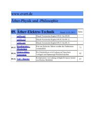
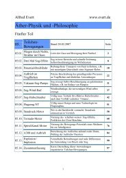
Picture <strong>07.09.</strong>03 upside left shows a<br />
view on these ´waved disks´ where<br />
downward showing flanks are marked<br />
red and upward showing flanks are<br />
marked blue. Black zigzag-line<br />
represents upward-downward track of<br />
air at its way from centre to border of<br />
that rotor.<br />
That picture upside right shows part of<br />
canal between both disks (grey), which<br />
are mounted at plan supporting disk. When disk is started turning, also air will become<br />
turning around system axis, based on friction of air at inner faces. Canal between both disks<br />
practically is a disk-shaped space with wave-shaped contours. From centre (right), air flows<br />
downward-outward (A, red), can fly outward unhindered within valley (B), afterward flowing<br />
upward again (C, blue) towards border (left) of disk.<br />
Here, cross-section of canal is drawn constant. The further outward air wanders, the wider<br />
space is available, i.e. density of air decreases. Air particles all times wander towards area of<br />
3
less density, because there they can fly longer distances between collisions. <strong>Schauberger</strong><br />
had installed some openings D within upper sheet, through which ´wrong air´ was allowed to<br />
enter canal. So mass-throughput is increased by that side-stream, corresponding to previous<br />
considerations.<br />
Picture <strong>07.09.</strong>03 at bottom shows canal, where contours of both disks (nearby) are sinusshaped.<br />
Resulting are sections with increasing cross-sectional surface (light blue) and<br />
sections with decreasing cross-sectional surface (dark blue). At middle of each up- resp.<br />
downward showing flank, bottlenecks are build. So that canal from inside towards outside<br />
represents a sequence of Laval-nozzles.<br />
Behind a bottleneck, air can flow into relative empty space (like e.g. at E) and especially<br />
through ´valleys´ or over the ´mountains´, air can flow outward unhindered. Afterward, air is<br />
dammed-up at area of more narrow cross-sections (like at F) and finally can move through<br />
bottleneck (like at G) by sound-speed, again flying into wider space. If both wave-disks were<br />
build by such contours, effect of accelerating flows by Laval-nozzles is realized at that<br />
<strong>Repulsine</strong>.<br />
Laval-Nozzle plus Side-Stream<br />
<strong>Schauberger</strong> mostly mounted these waved-sheets at plane supporting disk (grey beam at<br />
previous picture), so openings for ´wrong air´ could be installed only at one side. Naturally<br />
canal could be build also between disks more thick with corresponding contours, like<br />
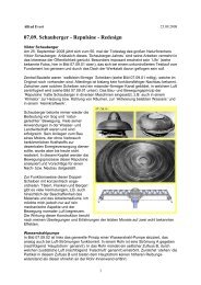
sketched upside of following picture <strong>07.09.</strong>04.<br />
Here contours are mirrored (each phase-shifted), however no longer sinus-shaped. Again<br />
there are sections with increasing cross-section-surface (like at A, light blue), where upside<br />
and downside air can fall outward relative unhindered. At the other hand, now bottleneck is<br />
arranged more narrow (like at C), so in front of comes up area of high density (like at B, dark<br />
blue). Additional influx now could come through openings from both sides (like at D).<br />
That construction thus would<br />
allow effect of Laval-nozzle<br />
within canal and also increased<br />
mass throughput is achieved<br />
by additional influx at both<br />
sides. However, at least at this<br />
drawing, ´wrong air´ enters little<br />
bit too late, because near most<br />
wide cross-section. Now must<br />
be checked whether that<br />
waved tracks are necessary at<br />
all or if no clearer design and<br />
easier construction is possible.<br />
Flat symmetrical Disk<br />
A suggestion for solution is shown at picture <strong>07.09.</strong>04 at bottom. Canal here is build between<br />
two symmetric constructional elements. Air wanders from centre to border (here form right to<br />
left) at rather straight way. Cross-section of canal is a sequence of narrowing and extending<br />
sections (here probably over-drawn).<br />
The air is dammed-up at area of narrowing (like at E, marked dark blue), air passes<br />
bottleneck (like at F) and flies outward into following area of wider space (like at G, marked<br />
light blue). Thus Laval-nozzles were build, all around, where air is accelerated up to soundspeed.<br />
Short behind bottlenecks, side-stream from both sides is ´sucked in´ (like at H), so<br />
stronger mass throughput is achieved.<br />
4
Suction works up to sound-speed, so one could use relative small number of Laval-nozzles<br />
(like here these three instead of fife at upside zigzag-track). At the other hand here is shown,<br />
also influx aside could be nozzle-shaped, so ´wrong air´ enters by fitting speed and direction<br />
into main-stream.<br />
General Track of Flow<br />
By that version more simple, now one can understand<br />
why <strong>Schauberger</strong>´s <strong>Repulsine</strong> was self-accelerating.<br />
Picture <strong>07.09.</strong>05 shows a view from aside towards rotor,<br />
which is assumed left-turning (like always here). Ringshaped<br />
areas of narrow canal-sections are marked dark<br />
blue, areas of extended cross-sections are marked light<br />
blue. General track of an air particle, representing all air<br />
movements, here is marked by black, yellow and red<br />
arrows.<br />
When starting system, air within canal also becomes<br />
rotating around system axis, based on friction at canal<br />
inner faces. Air moves forward within space (in turning sense), at first however air moves<br />
backward relative to rotor. Afterward in running mode, air however will turn faster than rotor,<br />
as discussed later.<br />
Air enters canal by central opening A and is pressed into area more narrow (dark blue).<br />
There exists relative high density and particles are accelerated strongly in turning sense of<br />
system, direct by friction at inner canal surfaces or indirectly via mutual collisions. These<br />
particles thus in principle move at circle-track, from which they can move outward through<br />
bottleneck rather slow. As a whole, thus particles move at an opening spiral track, like<br />
marked by yellow arrow B.<br />
Within area of bottleneck (transit from dark to light blue) movement of particles is directed<br />
outward-forward, so tangential or some more outward. Flow strongly becomes accelerated<br />
within bottleneck and particles can fly outward into following area of wider cross-sectional<br />
surface (light blue) relative unhindered, like marked by red arrow C, in nearby tangential<br />
direction. At this area now additional influx from aside enters main-stream (here not drawn),<br />
so wider space further outside is filled up by additional air masses.<br />
Generating Turning Momentum<br />
That air-mass with its high speed now hits onto dammed-up air in front of next narrowing<br />
(dark blue). That stream can not move further tangential-outward, but is redirected some<br />
more into circled track (with corresponding increased angle-speed). Opposite, that air-mass<br />
by itself presses air in front of narrowing forward in turning sense. Air can escape through<br />
bottleneck outward only relative slow, like here marked by yellow arrow D.<br />
That pressure within bottleneck is directed further forward and consequently now air-particles<br />
fly off bottleneck straight forward into next wide space (light blue), as marked by red arrow E.<br />
That movement process is repeated. However finally at third narrowing (dark blue), air no<br />
longer will be accelerated by friction of rotor surfaces. Air-masses here move faster forward<br />
than rotor is turning there. Via friction now rotor is accelerated by that fast moving air with its<br />
high density in front of next bottleneck, like marked by long yellow arrow F.<br />
After relative free flight through last extended section (light blue, with red arrow G) surplus<br />
speed via friction is transferred into turning momentum within a final narrow part of canal<br />
(grey, like upside at pictures of wave-shaped <strong>Repulsine</strong>).<br />
5
That movements process describes reason, why <strong>Repulsine</strong> was able to turn up until soundspeed.<br />
If rotating air of outlet of that rotor is guided back to central inlet, main-stream there<br />
already is turning and no longer must be accelerated in turning sense. If that backflow is not<br />
controlled, system can turn up self-accelerating until self-destruction. If that outlet-air is<br />
guided downward, that ´Ufo-<strong>Repulsine</strong>´ can fly off (where additional effects of ether-motions<br />
come up, based on fast rotation of solid bodies - however this can be discussed only by<br />
many new chapters of Ether-Physics).<br />
<strong>Repulsine</strong> with flat <strong>Rotor</strong><br />
Picture <strong>07.09.</strong>06 shows previous flat rotor with its symmetric constructional elements, now<br />
with some additional elements. At picture left, side-view at rotor is sketched, at picture right<br />
side longitudinal cross-sectional view through machine is sketched (only upper part by some<br />
larger scale). That rotor is drawn with horizontal shaft, which is beard within housing GE<br />
(grey). This rotor functions as turbine (red), some parts however function as pump (green).<br />
These drawings only show construction in general and are not true to scale. For example,<br />
canal here has only three bottlenecks, while in real machines more (and smaller) nozzles<br />
could be used. At this version, canal is build between four ring-shaped elements T1 to T4<br />
(light red). These constructional elements are fix connected by spokes SP (dark red, her e.g.<br />
six).<br />
Inlet of main-stream<br />
enters through<br />
openings between<br />
turbine-shaft TW (dark<br />
red) and first ringelement<br />
T1 (see arrow<br />
A). Between shaft and<br />
that ring, pump-blades<br />
PS (light green) are<br />
installed, transporting<br />
and pressing air from<br />
both sides into first<br />
bottleneck (dark blue).<br />
Afterward, air flows into<br />
wider space, where mass throughput is increased by influx of ´wrong air´ through openings<br />
between first and second ring-element (T1 and T2, see arrow B).<br />
These air masses are moving forward-outward into next narrowing, again are accelerated<br />
within next bottleneck, afterward flying into next extension area, where additional air enters<br />
from aside (see arrow C). That side-influx thus occurs through ring-shaped openings (light<br />
blue) between these ring-elements (T1 and T2 plus T2 and T3), only interrupted by spokes<br />
SP.<br />
As mentioned upside, air is accelerated within nozzles in direction forward-outward, sooner<br />
or later beyond turning-speed of rotor. These fast flows affect thrust at canal-surfaces (by<br />
friction, direct or indirect), especially at area of narrowings and relative high density there.<br />
Before air is leaving turbine, once again that thrust-situation should be organized. In addition,<br />
here that last narrowing is curved, so flows of radial level are redirected into axial direction<br />
towards both sides of rotor.<br />
Air flows off turbine (see arrow D) through that outlet (dark blue) between ring-elements T3<br />
and T4. Both ring-elements again are connected by spokes SP. However, within that outlet<br />
well could be installed additional turbine-blades TS (dark red). Via redirection of flow at these<br />
blades, additional turning momentum is generated at long lever arm.<br />
6
Air of main-stream ´disappears´ through central inlet-openings (transported by pump-blades<br />
PS) and also side-stream is ´sucked´ through openings of wrong-air. Air following from<br />
outside towards centre (see arrow F) will not flow radial inward but at spiral tracks inward<br />
curved. Air still is turning at outlet of turbine. That rotation however should be slower, so a<br />
´whirlwind´ comes up. Static pressure at circumference thereby is transmitted into kinetic<br />
pressure of faster turning flows near centre. System should not be closed hermetical, but<br />
housing should be partly open, so atmospheric pressure (see arrow E) weights on inward<br />
directed vortex, pressing and accelerating flows towards centre.<br />
Controlling-Problems<br />
Based on previous considerations, <strong>Schauberger</strong> <strong>Repulsine</strong> achieved acceleration of flows by<br />
Laval-nozzles and achieved increased mass throughput by influx of wrong air, both<br />
demanding no additional energy-input. By previous relative small and symmetric rotor, these<br />
effects are used ´straight´ and consequently.<br />
Bibliography of Viktor <strong>Schauberger</strong> tells, diverse versions of <strong>Repulsine</strong> (or Repulsator) were<br />
build in 1940 and following years, in the fifties also several ´Heimkraftwerke´ (home-powerstations),<br />
however all times ´regulation of revolutions´ made problems. Obviously it´s hard to<br />
build well controllable engine by only one rotating constructional element. It might make<br />
sense to use one (controllable) component for drive and<br />
an other component for taking off turning momentum. So<br />
functions of pump and turbine should be realized by<br />
different assemblies.<br />
Picture <strong>07.09.</strong>07 once more shows previous longitudinal<br />
cross-sectional view, however now that disk-like rotor<br />
functions only as turbine T (red). Ring-shaped elements<br />
of turbine still are connected by spokes SP, which now<br />
reach inward to turbine-shaft. At both side now pumps<br />
are installed at separated hollow-shafts (dark green) with<br />
corresponding pump-blades PS (light green). These<br />
pumps transport air into first narrowing of turbine and air<br />
already is rotating in turning sense of system.<br />
Mass-throughput of main-stream is controlled by revolutions of pumps. If pumps stand still,<br />
air through pump-blades moves contrary to general turning sense, so system will slow down<br />
and stop.<br />
Re-Design und Re-Production<br />
Viktor <strong>Schauberger</strong> nowhere had clearly defined that terminus ´<strong>Repulsine</strong>´ and also had<br />
never explained understandable decisive movement processes of that conception. Instead of<br />
he mentioned, quality of material would be important and transformation of working medium<br />
would occur - still not to grasp by common knowledge. So it´s not astonishing, many most<br />
different explanation of <strong>Repulsine</strong> exist and some of still sound rather mysterious.<br />
I suggest at first to concentrate at simple fluid-mechanic. I think these two well known effects<br />
of ´water-jet-pump´ and ´Laval-Nozzle´ respective combination of both processes is decisive<br />
´secret´. That will do for accelerating flows and increasing mass throughput - without<br />
corresponding strong input of energy. It would be fine if based at that new understanding,<br />
now finally a running <strong>Repulsine</strong> could be re-constructed.<br />
Evert / 25. September 2008 / www.evert.de<br />
7