07.09. Schauberger - Repulsine - Redesign - Rotor
07.09. Schauberger - Repulsine - Redesign - Rotor
07.09. Schauberger - Repulsine - Redesign - Rotor

You also want an ePaper? Increase the reach of your titles
YUMPU automatically turns print PDFs into web optimized ePapers that Google loves.
less density, because there they can fly longer distances between collisions. <strong>Schauberger</strong><br />
had installed some openings D within upper sheet, through which ´wrong air´ was allowed to<br />
enter canal. So mass-throughput is increased by that side-stream, corresponding to previous<br />
considerations.<br />
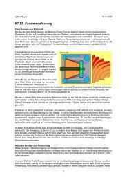
Picture <strong>07.09.</strong>03 at bottom shows canal, where contours of both disks (nearby) are sinusshaped.<br />
Resulting are sections with increasing cross-sectional surface (light blue) and<br />
sections with decreasing cross-sectional surface (dark blue). At middle of each up- resp.<br />
downward showing flank, bottlenecks are build. So that canal from inside towards outside<br />
represents a sequence of Laval-nozzles.<br />
Behind a bottleneck, air can flow into relative empty space (like e.g. at E) and especially<br />
through ´valleys´ or over the ´mountains´, air can flow outward unhindered. Afterward, air is<br />
dammed-up at area of more narrow cross-sections (like at F) and finally can move through<br />
bottleneck (like at G) by sound-speed, again flying into wider space. If both wave-disks were<br />
build by such contours, effect of accelerating flows by Laval-nozzles is realized at that<br />
<strong>Repulsine</strong>.<br />
Laval-Nozzle plus Side-Stream<br />
<strong>Schauberger</strong> mostly mounted these waved-sheets at plane supporting disk (grey beam at<br />
previous picture), so openings for ´wrong air´ could be installed only at one side. Naturally<br />
canal could be build also between disks more thick with corresponding contours, like<br />
sketched upside of following picture <strong>07.09.</strong>04.<br />
Here contours are mirrored (each phase-shifted), however no longer sinus-shaped. Again<br />
there are sections with increasing cross-section-surface (like at A, light blue), where upside<br />
and downside air can fall outward relative unhindered. At the other hand, now bottleneck is<br />
arranged more narrow (like at C), so in front of comes up area of high density (like at B, dark<br />
blue). Additional influx now could come through openings from both sides (like at D).<br />
That construction thus would<br />
allow effect of Laval-nozzle<br />
within canal and also increased<br />
mass throughput is achieved<br />
by additional influx at both<br />
sides. However, at least at this<br />
drawing, ´wrong air´ enters little<br />
bit too late, because near most<br />
wide cross-section. Now must<br />
be checked whether that<br />
waved tracks are necessary at<br />
all or if no clearer design and<br />
easier construction is possible.<br />
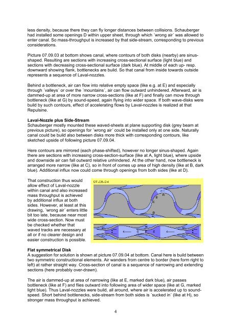
Flat symmetrical Disk<br />
A suggestion for solution is shown at picture <strong>07.09.</strong>04 at bottom. Canal here is build between<br />
two symmetric constructional elements. Air wanders from centre to border (here form right to<br />
left) at rather straight way. Cross-section of canal is a sequence of narrowing and extending<br />
sections (here probably over-drawn).<br />
The air is dammed-up at area of narrowing (like at E, marked dark blue), air passes<br />
bottleneck (like at F) and flies outward into following area of wider space (like at G, marked<br />
light blue). Thus Laval-nozzles were build, all around, where air is accelerated up to soundspeed.<br />
Short behind bottlenecks, side-stream from both sides is ´sucked in´ (like at H), so<br />
stronger mass throughput is achieved.<br />
4