07.09. Schauberger - Repulsine - Redesign - Rotor
07.09. Schauberger - Repulsine - Redesign - Rotor
07.09. Schauberger - Repulsine - Redesign - Rotor

Create successful ePaper yourself
Turn your PDF publications into a flip-book with our unique Google optimized e-Paper software.
Suction works up to sound-speed, so one could use relative small number of Laval-nozzles<br />
(like here these three instead of fife at upside zigzag-track). At the other hand here is shown,<br />
also influx aside could be nozzle-shaped, so ´wrong air´ enters by fitting speed and direction<br />
into main-stream.<br />
General Track of Flow<br />
By that version more simple, now one can understand<br />
why <strong>Schauberger</strong>´s <strong>Repulsine</strong> was self-accelerating.<br />
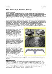
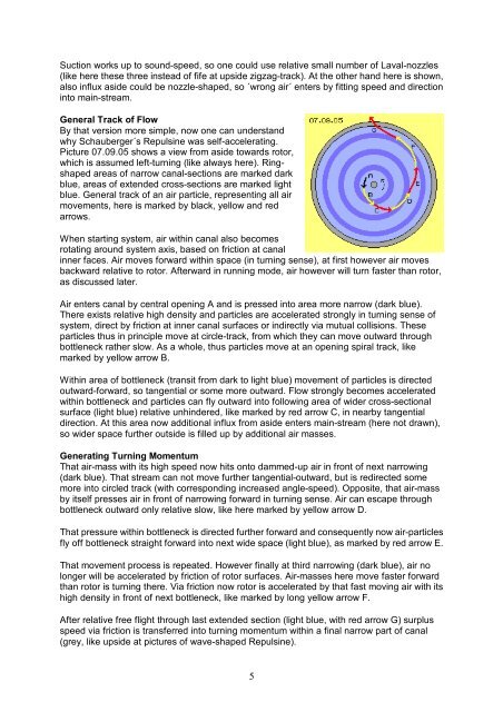
Picture <strong>07.09.</strong>05 shows a view from aside towards rotor,<br />
which is assumed left-turning (like always here). Ringshaped<br />
areas of narrow canal-sections are marked dark<br />
blue, areas of extended cross-sections are marked light<br />
blue. General track of an air particle, representing all air<br />
movements, here is marked by black, yellow and red<br />
arrows.<br />
When starting system, air within canal also becomes<br />
rotating around system axis, based on friction at canal<br />
inner faces. Air moves forward within space (in turning sense), at first however air moves<br />
backward relative to rotor. Afterward in running mode, air however will turn faster than rotor,<br />
as discussed later.<br />
Air enters canal by central opening A and is pressed into area more narrow (dark blue).<br />
There exists relative high density and particles are accelerated strongly in turning sense of<br />
system, direct by friction at inner canal surfaces or indirectly via mutual collisions. These<br />
particles thus in principle move at circle-track, from which they can move outward through<br />
bottleneck rather slow. As a whole, thus particles move at an opening spiral track, like<br />
marked by yellow arrow B.<br />
Within area of bottleneck (transit from dark to light blue) movement of particles is directed<br />
outward-forward, so tangential or some more outward. Flow strongly becomes accelerated<br />
within bottleneck and particles can fly outward into following area of wider cross-sectional<br />
surface (light blue) relative unhindered, like marked by red arrow C, in nearby tangential<br />
direction. At this area now additional influx from aside enters main-stream (here not drawn),<br />
so wider space further outside is filled up by additional air masses.<br />
Generating Turning Momentum<br />
That air-mass with its high speed now hits onto dammed-up air in front of next narrowing<br />
(dark blue). That stream can not move further tangential-outward, but is redirected some<br />
more into circled track (with corresponding increased angle-speed). Opposite, that air-mass<br />
by itself presses air in front of narrowing forward in turning sense. Air can escape through<br />
bottleneck outward only relative slow, like here marked by yellow arrow D.<br />
That pressure within bottleneck is directed further forward and consequently now air-particles<br />
fly off bottleneck straight forward into next wide space (light blue), as marked by red arrow E.<br />
That movement process is repeated. However finally at third narrowing (dark blue), air no<br />
longer will be accelerated by friction of rotor surfaces. Air-masses here move faster forward<br />
than rotor is turning there. Via friction now rotor is accelerated by that fast moving air with its<br />
high density in front of next bottleneck, like marked by long yellow arrow F.<br />
After relative free flight through last extended section (light blue, with red arrow G) surplus<br />
speed via friction is transferred into turning momentum within a final narrow part of canal<br />
(grey, like upside at pictures of wave-shaped <strong>Repulsine</strong>).<br />
5