Manual - Meterspec
Manual - Meterspec
Manual - Meterspec
You also want an ePaper? Increase the reach of your titles
YUMPU automatically turns print PDFs into web optimized ePapers that Google loves.
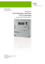
MT174<br />
Three-Phase Static Electricity<br />
Multi Tariff Meter<br />
with Maximum Demand Indicator<br />
and Load-profile<br />
Technical Description<br />
Version 1.2, 18.08.2011<br />
MT174 - Electronic three-phase<br />
time-of-use electricity meters<br />
The MT174 electronic three-phase meters are The meter software complies with WELMEC 7.2<br />
designed for measurement and registration of Issue 1 Software Guide (Measuring Instruments<br />
active, reactive and apparent energy and Directive 2004/22/EC).<br />
demand in three-phase four-wire networks.<br />
They can be connected directly to the network. The MT174 meters are designed for mechanical<br />
The metering and technical properties of the environment M1, electromagnetic environment<br />
meters comply with the EN 50470-1 and -3 E2 and climatic environment -40°C ... +60°C,<br />
European standards for active energy meters, relative humidity 95% non-condensing, closed<br />
classes A and B, as well as with the IEC 62053- location. The meters can be installed in any<br />
21 and IEC 62052-11 international standards for position.<br />
electronic meters of active energy for classes 1<br />
and 2, and optionally with the IEC 62053-23 The meters are designed and manufactured in<br />
international standard for electronic meters of compliance with the ISO 9001 (2000) standard.<br />
reactive energy for classes 2 and 3.<br />
A built-in time-switch complies with the IEC<br />
62054-21 and IEC 62052-21 standards. It enables<br />
energy registration in up to four tariffs.
MT174 - Electronic three-phase electricity meters<br />
with maximum demand and LP<br />
MT174 meter properties:<br />
• Meter accuracy<br />
• Class A or B in compliance with EN 50470-3<br />
(or 2 or 1 in compliance with IEC 62053-21)<br />
for active energy<br />
• Class 3 or 2 for reactive energy (option)<br />
• Class 3 or 2 for apparent energy (option)<br />
• Meter software in compliance with<br />
WELMEC 7.2 Issue 1<br />
• Measured quantities<br />
• Energy (active, reactive and apparent)<br />
• Demand (active, reactive and apparent)<br />
• Reactive energy and demand by quadrants<br />
• Instantaneous power<br />
• Phase voltages (UL1, UL2, UL3)<br />
• Phase currents (IL1, IL2, IL3)<br />
• Phase power factors<br />
• Frequency<br />
• Modes of energy measurement and<br />
registration<br />
• For one-way energy flow direction (import),<br />
with an electronic reverse running stop<br />
• For two energy flow directions (import,<br />
export)<br />
• For two-way energy flow direction, with always<br />
positive registration, i.e. energy flowing<br />
in the export direction is registered as it flows<br />
in import direction too (only for active energy)<br />
• Connection:<br />
• Direct<br />
• Via CT<br />
• Networks:<br />
• 3-phase 4-wire<br />
• 3-phase 3-wire<br />
• 1-phase 2-wire<br />
• Meter quality:<br />
• Due to high accuracy and long term stability<br />
of the metering elements no meter recalibration<br />
is required over its lifetime<br />
• Long meter lifetime and high meter reliability<br />
• High immunity to EMC<br />
• Wide voltage range of measurement with<br />
declared meter accuracy: 0.3Ur to 1.3Ur<br />
• RTC:<br />
• Accuracy better than ±3 min/year at 23°C<br />
• RTC operation reserve 5 years<br />
• Back-up power supply Li-battery<br />
• Indication of low Li-battery (option)<br />
• Time-of-use registration (up to 4 tariffs):<br />
• Tariffs change-over by internal real-time<br />
clock<br />
• Optional tariff inputs for external tariff<br />
change-over<br />
• LCD-display:<br />
• Large LCD in compliance with the VDEW<br />
requirements<br />
• EDIS code for data identification<br />
• LCD back-light on request<br />
• Data display modes:<br />
• Automatic cyclic data display with default<br />
display time of 8 sec.<br />
• <strong>Manual</strong> data display mode (by pressing the<br />
Scroll push-button)<br />
• Optional data display when the meter is in<br />
no-power state<br />
• Indicators:<br />
• LCD:<br />
- Valid tariff at the moment<br />
- Meter status and alarms<br />
- Energy flow direction<br />
- Phase voltage presence and phase<br />
voltage sequence<br />
- reversed energy flow through a particular<br />
metering element<br />
• LEDs:<br />
- Imp/kWh<br />
- Imp/kvarh (at active and reactive energy<br />
meters)<br />
- Imp/kVAh (at kWh-, kvarh-, kVAh-meters)<br />
• Powerful load-profile recorder:<br />
• Up to 8-channels<br />
• More than 790 days of registration at 1<br />
channel, 1-hour registration period<br />
• Communication channels:<br />
• Infrared optical port in compliance with IEC<br />
62056-21 for local programming and data<br />
down-loading<br />
• RS485 serial interface (option)<br />
• Protocol IEC 62056 - 21, mode C<br />
• Pulse outputs:<br />
• Class A by IEC 62053-31 (option)<br />
• Optomos relay with make contact (option)<br />
• Plastic meter case:<br />
• Made of high quality self-extinguishing UV<br />
stabilized material that can be recycled<br />
• Double insulation<br />
• IP54 protection against dust and water<br />
penetration (by IEC 60529)<br />
• Mechanical environment: M1<br />
• Electromagnetic environment: E2<br />
4 of 36
MT174 - Electronic three-phase electricity meters<br />
with maximum demand and LP<br />
• At direct connected meters:<br />
• Current terminals<br />
- Assure good connection with all types of<br />
conductors<br />
- Do not damage conductors<br />
• Potential links<br />
- Sliding self-braking potential links enable<br />
quick disconnection of current and voltage<br />
circuitries<br />
- Can be located in a terminal block compartment<br />
or under a meter cover<br />
• Antifraud functions:<br />
• Detectors (optional)<br />
- meter cover opening<br />
- terminal cover opening<br />
- reversed energy flow direction<br />
- external permanent magnetic field<br />
• Indicators (optional)<br />
- meter cover opening<br />
- terminal cover opening<br />
- reversed energy flow direction trough<br />
each of metering elements<br />
- external permanent magnetic field<br />
• Fraud energy registers (optional)<br />
- energy consumed since the meter cover<br />
has been opened<br />
- energy consumed since the terminal<br />
cover has been opened<br />
- energy consumed since reversed<br />
energy flow has been detected<br />
- energy consumed since external<br />
permanent magnetic field has been<br />
detected<br />
• Counters of events (optional)<br />
- meter cover opening<br />
- terminal cover opening<br />
- reversed energy flow direction<br />
- external permanent magnetic field<br />
• Counters of elapsed time (optional)<br />
- since meter cover has been opened<br />
- since terminal cover has been opened<br />
- since reversed energy flow has been<br />
detected<br />
- since external permanent magnetic field<br />
has been detected<br />
- of total energy registration<br />
- of energy registration in a particular tariff<br />
• Time-stamps (optional)<br />
- of the last meter cover opening<br />
- of the last terminal cover opening<br />
- of the last reversed energy flow<br />
detection<br />
- of the last external permanent magnetic<br />
field tampering<br />
• Change of set parameters protected with<br />
a sealed pushbutton (optional)<br />
5 of 36
MT174 - Electronic three-phase electricity meters<br />
with maximum demand and LP<br />
1. Meter appearance<br />
8<br />
10<br />
13<br />
9<br />
14<br />
3<br />
12<br />
4<br />
2<br />
5<br />
6<br />
7<br />
3<br />
1<br />
12<br />
The meter cover is made of transparent polycarbonate.<br />
It is fixed to the meter base with two<br />
sealing screws, which prevents access to the meter<br />
interior without breaking the seals.<br />
A nickel-plated iron ring in the right top corner is<br />
used for attaching an optical probe to the optical<br />
port (item 5). A push-button for data scrolling is<br />
positioned on the meter right side (item 6). The<br />
reset push-button cover (item 7) is joined with a<br />
hinge to the meter cover and can be sealed<br />
independently.<br />
1.2. Terminal block<br />
The terminal block is made of self-extinguishing<br />
polycarbonate. It can be used either for direct or CT<br />
meter connection.<br />
11<br />
The terminal block cover (item 11) can be long or<br />
short. A meter connection diagram is stuck on its<br />
inner side. The terminal block cover is fixed with<br />
two sealing screws (item 12).<br />
Fig. 1: Meter parts<br />
1. Meter base 8. LED imp/kWh<br />
2. Meter cover 9. LED imp/kvarh (option)<br />
3. Meter cover fixing<br />
screw<br />
10. LED imp/kVAh (option)<br />
11. Terminal block cover<br />
4. LCD 12. Terminal cover fixing<br />
5. Optical port Screw<br />
6. Scroll push-button 13. Meter data<br />
7. Reset push-button 14. Legend<br />
cover<br />
1.2.1. Terminal block for direct connected<br />
meters<br />
The terminal block for direct connected meters<br />
contains current terminals, auxiliary terminals and<br />
potential links for power supply of the voltage<br />
metering circuitry.<br />
Screws for fixing the meter cover (item 3) are<br />
sealed with metrological seals.<br />
Screws for fixing the terminal block cover (item 12)<br />
are sealed with seals of electric utility.<br />
1.1. Meter case<br />
A compact meter case consists of a meter base<br />
(item 1) with a terminal block and three fixing<br />
elements for mounting the meter, a meter cover<br />
(item 2) and a terminal block cover (item 11). The<br />
meter case is made of self-extinguishing UV<br />
stabilized polycarbonate which can be recycled.<br />
The meter case ensures double insulation and IP54<br />
(IEC 60529) protection level against dust and water<br />
penetration.<br />
On the back side of the meter base under the top<br />
edge there is the top meter fixing element. On<br />
request an extended plastic or metal top fixing<br />
element can be attached to the back side of the<br />
meter base.<br />
Fig. 2: Terminal block of direct connected meters<br />
1. Current terminals 3. Auxiliary voltage terminals<br />
for an add-on unit<br />
2. Auxiliary terminals 4. Terminal cover opening<br />
detector<br />
The current terminals (item 1) are cage type and<br />
are made of nickel plated steel. They are universal<br />
terminals for all types of conductors made either of<br />
copper or aluminium. The current terminals are<br />
made in two sizes:<br />
• For conductors with maximum cross section<br />
up to 25 mm 2 (Imax = 85 A),<br />
• For conductors with maximum cross section<br />
up to 35 mm 2 (Imax = 120 A).<br />
6 of 36
MT174 - Electronic three-phase electricity meters<br />
with maximum demand and LP<br />
The 85 A terminal blocks has only one screw per<br />
current terminal, while 120 A terminal blocks has<br />
two screws per current terminal. Due to indirect<br />
pressure to the conductors the terminal screws do<br />
not damage it. The current terminals make a reliable<br />
and durable contact regardless if the conductor<br />
is made of copper or aluminium.<br />
1<br />
2<br />
Voltage metering elements are power supplied via<br />
potential links. Sliding potential links are selfbraking<br />
and enable easy disconnection of current<br />
and voltage metering circuitry. In the metering<br />
mode they should be in their lowest position (closed<br />
contact), and in the meter testing mode they should<br />
be in their highest position (opened contact). On<br />
request, the potential links can be located under the<br />
meter cover.<br />
1. Sliding potential links<br />
(opened contacts)<br />
3. Terminals of auxiliary voltages<br />
2. Phase voltage test<br />
contacts<br />
a. Potential links in the terminal block<br />
1<br />
2<br />
1<br />
2<br />
3<br />
1. Detector of terminal<br />
cover opening<br />
2. Phase voltage test<br />
contacts<br />
3. Sliding potential links (opened contacts)<br />
Fig. 4: Potential links in the terminal block of<br />
direct connected meters for Imax = 120 A<br />
1.2.2. Terminal block of CT operated meters<br />
The CT operated meters have separate voltage<br />
terminals (Fig. 5, item 2) in the terminal block. They<br />
are used for supplying the voltage metering<br />
circuitry. The voltage terminals are equal to the<br />
current terminals (Fig. 5, item 1). The current and<br />
voltage terminals are made of solid brass with a 5<br />
mm bore diameter; the conductors are fixed in the<br />
terminals with two screws.<br />
3<br />
4<br />
1<br />
2<br />
3<br />
1. Detector of terminal<br />
cover opening<br />
2. Phase voltage test<br />
contacts<br />
b. Potential links under meter cover<br />
Fig. 3: Terminal blocks of<br />
direct connected meters for Imax = 85 A<br />
1. Current terminals 3. Auxiliary terminals<br />
2. Voltage terminals 4. Auxiliary voltage<br />
terminals for add-on unit<br />
Fig. 5: Terminal block of a CT operated<br />
meter<br />
1.2.3. Auxiliary terminals<br />
Up to six auxiliary terminals can be built in a<br />
terminal block. They are used for tariff inputs,<br />
impulse outputs or tariff outputs or RS485 interface.<br />
Due to a limited number of auxiliary terminals, all<br />
stated inputs and outputs as well as the interface<br />
can not be built in the meter at the same time. The<br />
bore diameter of the auxiliary terminals is 3.5 mm.<br />
Wires are fixed with a screw. Three auxiliary<br />
7 of 36
MT174 - Electronic three-phase electricity meters<br />
with maximum demand and LP<br />
voltage terminals for power supply of an external<br />
device can be also built-in.<br />
The auxiliary terminals are nickel-plated at a<br />
tropical meter version.<br />
The auxiliary terminals enable combinations of the<br />
following meter functionalities:<br />
Version<br />
Left side<br />
auxiliary<br />
terminals<br />
Right side<br />
auxiliary<br />
terminals<br />
1 Two tariff inputs Two pulse outputs<br />
2 Two tariff inputs RS485 interface<br />
3 Two pulse or tariff<br />
outputs<br />
RS485 interface<br />
Note:<br />
On request, an additional top meter fixing<br />
element shown in Fig. 7 can be attached to<br />
the MT174 meters with a long terminal cover<br />
(shown in Fig. 6).<br />
1.4. Meter sealing places<br />
The meters are sealed at the following places:<br />
1. The screws of the meter cover - metrological<br />
seals<br />
2. The screws of the terminal cover - electric<br />
utility seals<br />
3. The hinged cover of the Reset pushbutton -<br />
electric utility seals<br />
1.3. Over-all dimensions<br />
Meter fixing dimensions comply with the DIN 43857<br />
standard.<br />
3<br />
1 1<br />
2 2<br />
Fig. 6 - Meter with a long terminal cover<br />
Fig. 8 - Places of sealing the MT174 meters<br />
Fig. 7 - Meter with a short terminal cover and<br />
an additional top meter fixing element<br />
8 of 36


