522 - Meterspec
522 - Meterspec
522 - Meterspec

You also want an ePaper? Increase the reach of your titles
YUMPU automatically turns print PDFs into web optimized ePapers that Google loves.
Solid state single phase meter<br />
User manual
User manual S2AS-100 / 200 Solid State Single Phase Meter<br />
Introduction<br />
Introduction<br />
Range of validity<br />
The present user manual applies to the basic version of the meters:<br />
• S2AS-100 (for single phase two wire system with installer switch)<br />
• S2AS-200 (for single phase two wire system without inst. switch)<br />
Explanations without specific type details apply to both types.<br />
Purpose<br />
Target group<br />
Conditions<br />
Subdivision<br />
The user manual contains all the information required for application of the<br />
meters for the intended purpose. This includes:<br />
• Provision of knowledge concerning characteristics, construction and<br />
function of the meters<br />
• Information about possible dangers, their consequences and measures<br />
to prevent any danger<br />
• Details concerning the performance of all work throughout the service<br />
life of the meters (parametrizing, installation, commissioning, operation,<br />
maintenance, shutting down and disposal)<br />
The contents of this user manual are intended for technically qualified personnel<br />
of energy supply companies responsible for the system planning,<br />
installation and commissioning, operation, maintenance, decommissioning<br />
and disposal of the meters.<br />
The user of this manual has received instruction in basic electrical principles,<br />
in particular the various principal types of circuit for energy measurement.<br />
This user manual is divided in a logical manner suitable for learning and<br />
application, i.e. the individual chapters follow the sequence of information<br />
probably required during the various phases of the service life of the meters.<br />
This provides the following structure:<br />
• Chapter 1 Description of unit<br />
• Chapter 2 Safety<br />
• Chapter 3 Construction and Function<br />
• Chapter 4 Control elements and displays<br />
• Chapter 5 Programming / Interrogation Interface<br />
• Chapter 6 Installation and commissioning<br />
• Chapter 7 Data readout<br />
• Chapter 8 Metering testing<br />
• Chapter 9 Detection of faults<br />
• Chapter 10 Decommissioning, disposal<br />
Siemens Metering AG<br />
H 71 0200 0015 en 1st edition<br />
0-3
User manual S2AS-100 / 200 Solid State Single Phase Meter<br />
Table of contents<br />
Table of contents<br />
1 Description of unit........................................................................ 1<br />
1.1 Review............................................................................................ 1<br />
1.1.1 General Review.............................................................................. 1<br />
1.1.2 Type designation ............................................................................ 2<br />
1.2 Technical Data ............................................................................... 3<br />
1.2.1 Voltage Values ............................................................................... 3<br />
1.2.2 Current Values ............................................................................... 3<br />
1.2.3 Frequency values ........................................................................... 4<br />
1.2.4 Power Consumption ....................................................................... 4<br />
1.2.5 Measuring accuracy ....................................................................... 4<br />
1.2.6 External influences ......................................................................... 5<br />
1.2.8 Output Values................................................................................. 6<br />
1.2.9 Opto- Interface according IEC 1107............................................... 7<br />
1.2.10 Dimensions..................................................................................... 7<br />
1.2.11 Connections ................................................................................... 8<br />
2 Safety............................................................................................. 1<br />
2.1 Safety information .......................................................................... 1<br />
2.2 Responsibilities .............................................................................. 1<br />
2.3 Safety regulations........................................................................... 2<br />
3 Construction and Function ......................................................... 1<br />
3.1 Metering Principle........................................................................... 1<br />
3.2 Reset and Initialisation ................................................................... 2<br />
3.2.1 Normal Reset ................................................................................. 2<br />
3.3 Power Down Operation .................................................................. 2<br />
3.4 Memory Access.............................................................................. 3<br />
3.5 Metering ......................................................................................... 3<br />
3.5.1 Register Model ............................................................................... 3<br />
3.5.2 Auxiliary input terminal ................................................................... 4<br />
3.5.3 Total Register ................................................................................. 4<br />
3.5.4 Active Rate selection...................................................................... 4<br />
3.6 Configuration File ........................................................................... 4<br />
4 Control elements and displays ................................................... 1<br />
4.1 LCD Display ................................................................................... 1<br />
4.1.1 Display specification....................................................................... 1<br />
4.1.2 Normal Displays ............................................................................. 1<br />
4.1.3 Dial Checks .................................................................................... 2<br />
4.1.4 Annunciators .................................................................................. 2<br />
4.2 Switch Control ................................................................................ 2<br />
4.2.1 SAS-100 ......................................................................................... 2<br />
4.2.2 S2AS-200 ....................................................................................... 3<br />
4.3.1 Tariff ID........................................................................................... 3<br />
4.3.2 Meter Serial Number ...................................................................... 3<br />
0-4 Siemens Metering AG<br />
H 71 0200 0015 en 1st edition
User manual S2AS-100 / 200 Solid State Single Phase Meter<br />
Introduction<br />
5 Programming / Interrogation Interface .......................................1<br />
5.1 Optical Communication Port ...........................................................1<br />
6 Installation and commissioning..................................................1<br />
6.1 Introduction.....................................................................................1<br />
6.2 Material and tools required .............................................................1<br />
6.3 Mounting the meter.........................................................................2<br />
6.4 Connecting meter ...........................................................................3<br />
6.5 Check of connections .....................................................................3<br />
6.6 Commissioning and functional check .............................................4<br />
7 Data readout..................................................................................1<br />
8 Meter Testing ................................................................................1<br />
8.1 Calibration link ................................................................................1<br />
8.2 Calibration LED Output...................................................................1<br />
9 Detection of faults ........................................................................1<br />
9.1 Error Messages ..............................................................................1<br />
9.2 Tamper / Fraud...............................................................................1<br />
9.3 Watchdog and Exception Handling.................................................1<br />
9.4 Reverse Detect...............................................................................1<br />
9.5 Creep..............................................................................................1<br />
9.6 Mains Failure ..................................................................................2<br />
9.7 Failure Tolerance............................................................................2<br />
9.8 Energy Register Locking.................................................................2<br />
10 Decommissioning, disposal ........................................................1<br />
Siemens Metering AG<br />
H 71 0200 0015 en 1st edition<br />
0-5
User manual S2AS-100 / 200 Solid State Single Phase Meter<br />
Description of unit<br />
1 Description of unit<br />
1.1 Review<br />
1.1.1 General Review<br />
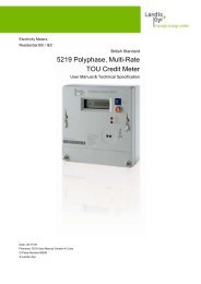
View of meter:<br />
IEC1107<br />
Interface<br />
BS compliant<br />
Terminal<br />
Fig.1<br />
General view of meter<br />
Residential metering<br />
Modular design<br />
The S2AS meters form a family of solid state single phase meters to cover<br />
the whole range of residential metering applications. Single or two rate<br />
register, pulse output and communcation interface according IEC 1107.<br />
The meters can be used for currents up to 100 A.<br />
The meter is equipped with features to enable the detection of fraud<br />
attempts. The meter has a reverse energy register as well as a register<br />
recording the number of power-on hours it sees.<br />
A unique feature is the low power consumption which helps to reduce the<br />
network losses<br />
The meter fulfils the requirements of today’s metering practice, while the<br />
design concept is already prepared to cope with tomorrow’s needs in a fully<br />
liberalised market. Future requirements can be realised in the form of<br />
external circuits incorporated in a module unit that can be adapted to the<br />
basic meter (adaptive meter concept).<br />
Siemens Metering AG<br />
H 71 0200 0015 en 1st edition<br />
1-1
User manual S2AS-100 / 200 Solid State Single Phase Meter<br />
Description of unit<br />
Case<br />
The meter is housed in a polycarbonate case designed for the easy fitting<br />
of add-on modules. Through its small size and low weight the S2AS meter<br />
saves costs in logistics.<br />
1.1.2 Type designation<br />
S2AS-100<br />
Module port<br />
Meter with installer switch<br />
The installer switch allows<br />
the supply to the premises to<br />
be disconnected without<br />
drawing the main fuse or<br />
disconnecting cables<br />
S2AS-200<br />
Meter without installer switch<br />
Module port<br />
1-2 Siemens Metering AG<br />
H 71 0200 0015 en 1st edition
User manual S2AS-100 / 200 Solid State Single Phase Meter<br />
Description of unit<br />
1.2 Technical Data<br />
1.2.1 Voltage Values<br />
Rated Voltage<br />
• Nominal as per IEC 61036.................................................... 230V + 10%<br />
• Range for mains input voltages ................................. 0.8 up to 1.15 x Un<br />
Note:<br />
1. The meter is fully operational within 4 seconds of the application of a<br />
voltage supply in the above range<br />
2. The meter will power down and inhibit all operations if the mains<br />
voltage falls below 150VAC.<br />
3. Between ISO V and 184 V operation is not guaranteed, however the<br />
meter will not malfunction, corrupt stored data or register spurious<br />
consumption and will power up or down cleanly once the mains input<br />
voltage rises above or below these values.<br />
4. The requirements specified in 2 and 4 above, are independent of the<br />
rate of change of the mains input voltage.<br />
5. The meter will remain operational for mains voltage interruptions of up<br />
to 0.2 seconds. For interruptions of greater than 0.2 seconds, the meter<br />
may power down and up again but shall do so without malfunction,<br />
corrupting data or registering spurious electricity consumption.<br />
1.2.2 Current Values<br />
Basic current Ib ................................................................either 10A or 20A<br />
Maximum Current Imax..................................................either 80A or 100A<br />
Maximum measuring range ...........up to 120A without exceeding 5% error<br />
Creep inhibit circuit operating ............................... at approximately 40mA<br />
Note: Current sensing is by means of a shunt.<br />
Siemens Metering AG<br />
H 71 0200 0015 en 1st edition<br />
1-3
User manual S2AS-100 / 200 Solid State Single Phase Meter<br />
Description of unit<br />
1.2.3 Frequency values<br />
Rated frequency ...................................................................................50Hz<br />
1.2.4 Power Consumption<br />
• voltage circuit burden .............. less than 0.5W and 9VA. Typically 0.4 W<br />
• VA burden of the current circuit at Imax ..........less than 0.25W / 0.25 VA<br />
1.2.5 Measuring accuracy<br />
Accuracy<br />
• Accuracy class to IEC 61036 ........................................................ class 2<br />
Unity Power Factor at 20°C environmental temperature<br />
1.5<br />
1<br />
0.5<br />
% Error<br />
0<br />
-0.5<br />
0 20 40 60 80 100<br />
-1<br />
-1.5<br />
Current (A)<br />
Unity power factor<br />
1.5<br />
1<br />
% Error<br />
0.5<br />
0<br />
-0.5<br />
0 20 40 60 80 100<br />
253v<br />
220v<br />
198v<br />
-1<br />
-1.5<br />
Current (A)<br />
1-4 Siemens Metering AG<br />
H 71 0200 0015 en 1st edition
User manual S2AS-100 / 200 Solid State Single Phase Meter<br />
Description of unit<br />
Power Factor = 0.5 Lagging<br />
1.5<br />
1<br />
% Error<br />
0.5<br />
0<br />
-0.5<br />
0 20 40 60 80 100<br />
253v<br />
220v<br />
198v<br />
-1<br />
-1.5<br />
Current (A)<br />
1.2.6 External influences<br />
Temperature range<br />
• Operation....................................................................... -10 °C to +45 °C<br />
• Storage .......................................................................... -25 °C to +70 °C<br />
Temperature Coefficient<br />
Current (A) PF Mean Temp Coefficient<br />
%/K<br />
1 1 -0.009<br />
2 0.5 -0.016<br />
10 1 -0.015<br />
10 0.5 -0.0019<br />
80 1 -0.016<br />
80 0.5 -0.005<br />
Insulation requirements class 2.......................................................... 4kV*<br />
(*withstand capability between the voltage and current terminals, including<br />
the auxiliary terminals and all metal/conductive parts which the consumer<br />
can touch)<br />
Climatic / Type Approval...................according to IEC 61036 and OFFER*<br />
*(UK Office of the Electricty Regulator) additional requirements for type<br />
approval of certified meters and indoor meters<br />
Siemens Metering AG<br />
H 71 0200 0015 en 1st edition<br />
1-5
User manual S2AS-100 / 200 Solid State Single Phase Meter<br />
Description of unit<br />
Electromagnetic compatibility<br />
• Electrostatic discharges ................................................to IEC 61000-4-2<br />
− Contact discharges....................................................................... 8 kV<br />
• Electromagnetic high frequency fields...........................to IEC 61000-4-2<br />
− 27 MHz up to 500 MHz.......................................... at least 10 V per m<br />
− 100 kHz up to 1 GHz .............................................. typical 30 V per m<br />
• Line transients ................................................................. to IEC 61000-4-<br />
− for current and voltage circuits...................................................... 2 kV<br />
− for auxiliary circuits > 40 V............................................................ 1 kV<br />
• Radio interference suppression.........................to IEC/CISPR 22 class B<br />
1.2.8 Output Values<br />
Display<br />
• Type ................................................................. liquid crystal display LCD<br />
• Digit size........................................................................................... 6mm<br />
• Number of positions ............................................................................... 8<br />
The S0 pulse output<br />
• Pulse rise/fall time......................................................................< 5mS<br />
• Mark duration...........................................................................> 80mS<br />
• Space duration.........................................................................> 30mS<br />
• Maximum open circuit voltage ......................................................27V<br />
• Pulse Scaling .......................................................... 1‘000 Pulses/kWh<br />
• Current........................................................................................27mA<br />
• Pulse length.............................................................................. 280ms<br />
• Maximum line length................................................................... 0.5 m<br />
Note: It is available on two auxiliary terminals on the bottom of the S2AS-<br />
100 version of the meter. Note that these output terminals are polarised.<br />
1-6 Siemens Metering AG<br />
H 71 0200 0015 en 1st edition
User manual S2AS-100 / 200 Solid State Single Phase Meter<br />
Description of unit<br />
1.2.9 Opto- Interface according IEC 1107<br />
Programming / Interrogation Interface (“Opto Port”)<br />
• Type............................................. bi-directional communication interface<br />
• Standard ........................................... protocol complying with IEC 61107<br />
Subsequent communication at >4800 baud may be utilised by add-on<br />
modules.<br />
• Opining rate ...................................................C-a and C-b with 300 baud<br />
• Subsequent rate by use of add on modules .........................> 4800 baud<br />
• Application ................................................................................................<br />
− tariff programming and meter interrogation<br />
− reading communication<br />
1.2.10 Dimensions<br />
Weight...................................................................................................450 g<br />
External Dimensions ....................................................................................<br />
• Width..............................................................................................95 mm<br />
• Heigth ..........................................................................................144 mm<br />
• Depth .............................................................................................54 mm<br />
Suspension ...................................................................................................<br />
• Heigth .......................................................................................119.5 mm<br />
• Width...........................................................................................47.5 mm<br />
Normal configuration: short split terminal door<br />
Option available with long terminal door<br />
Siemens Metering AG<br />
H 71 0200 0015 en 1st edition<br />
1-7
User manual S2AS-100 / 200 Solid State Single Phase Meter<br />
Description of unit<br />
1.2.11 Connections<br />
Terminals<br />
• Type ........................................................................ screw type terminals<br />
• Diameter<br />
normal...................................................... 8.5 mm<br />
special ..................................................... 9.5 mm<br />
• Screw dimensions ...................................................................... M6 x 14<br />
− head diameter ................................................................ max. 6.6 mm<br />
− cross-slot ......................................... type Z, size 2, to ISO-4757-1983<br />
− slot ....................................................................... 0.8 +0.2/+0.06 mm<br />
• Tightening torque .....................................................................max. 3 Nm<br />
Terminal block front view<br />
Module port<br />
PAT. PENDING<br />
L<br />
N<br />
N<br />
ON<br />
1 2 3 4<br />
12<br />
13 10<br />
L<br />
The module port provides line<br />
and neutral connections for the<br />
supply to the external module.<br />
The module port power<br />
consumption will be recorded by<br />
the meter.<br />
The acces could be proteted by<br />
a lead or a brass seal.<br />
Terminal block below view<br />
Connection diagram<br />
1<br />
1 2<br />
+<br />
-<br />
12<br />
13<br />
3 10 4<br />
L<br />
N<br />
S0<br />
L<br />
N<br />
Tariff control<br />
1-8 Siemens Metering AG<br />
H 71 0200 0015 en 1st edition
User manual S2AS-100 / 200 Solid State Single Phase Meter<br />
Safety<br />
2 Safety<br />
2.1 Safety information<br />
Attention is drawn as follows in the individual chapters of this user manual<br />
with classified word symbols and pictographs to the relevant danger level,<br />
i.e. the severity and probability of any danger:<br />
WARNING<br />
For a possibly dangerous situation, which could result in severe physical<br />
injury or fatality.<br />
CAUTION<br />
For a possibly dangerous situation, which could result in minor physical<br />
injury or material damage.<br />
NOTE<br />
For a possibly dangerous situation, in which the product or an article in its<br />
environment could be damaged and for general details and other useful<br />
information to simplify the work.<br />
In addition to the danger level, all safety information also describes the type<br />
and source of the danger, its possible consequences and measures to<br />
counteract the danger.<br />
2.2 Responsibilities<br />
The owner of the meters – normally the power supply company – is responsible<br />
that all persons engaged on work with meters:<br />
1. Have read and understood the relevant sections of the user manual.<br />
2. Are sufficiently qualified for the work to be performed.<br />
3. Strictly observe the safety regulations (according to section 0) and the<br />
operating information in the individual chapters.<br />
In particular, the owner of the meters bears responsibility for the protection<br />
of persons, prevention of material damage and the training of personnel<br />
(Siemens Metering Ltd. provides training courses for this purpose on specific<br />
equipment; please contact the relevant agent if interested).<br />
Siemens Metering AG<br />
H 71 0200 0015 en 1st edition<br />
2-1
User manual S2AS-100 / 200 Solid State Single Phase Meter<br />
Safety<br />
2.3 Safety regulations<br />
The following safety regulations must be observed at all times:<br />
• The meter connections must not be under voltage during installation or<br />
when opening. Contact with live parts is dangerous to life. The relevant<br />
preliminary fuses should therefore be removed and kept in a safe place<br />
until the work is completed, so that other persons cannot replace them<br />
unnoticed.<br />
• Local safety regulations must be observed. Installation of the meters<br />
must be performed exclusively by technically qualified and suitably<br />
trained personnel.<br />
• The meters must be held securely during installation. They can cause<br />
injuries if dropped.<br />
• Meters which have fallen must not be installed, even if no damage is<br />
apparent, but must be returned for testing to the service and repair department<br />
responsible (or the manufacturer). Internal damage can result<br />
in functional disorders or short-circuits.<br />
• The meters must on no account be cleaned with running water or with<br />
high pressure devices. Water penetrating can cause short-circuits.<br />
2-2 Siemens Metering Ltd<br />
H 71 0200 0015 en 1st edition
User manual S2AS-100 / 200 Solid State Single Phase Meter<br />
Construction and Function<br />
3 Construction and Function<br />
3.1 Metering Principle<br />
The metering principle is composed of two major items, the shunt and the<br />
‘Sapphire’ ASIC. The shunt is used to sense the current flowing through<br />
the meter and the signal form, together with a voltage signal is fed into the<br />
ASIC which then calculates the instantaneous power.<br />
The use of the ASIC together with a majority of Surface Mounted Devices<br />
enables a high level of integration to be achieved. These factors are crucial<br />
to provide a meter of high accuracy and high reliability.<br />
Siemens Metering Ltd<br />
H 71 0200 0015 en 1st edition<br />
3-1
User manual S2AS-100 / 200 Solid State Single Phase Meter<br />
Construction and Function<br />
3.2 Reset and Initialisation<br />
3.2.1 Normal Reset<br />
The meter does not use any battery back up of RAM, so in order to protect<br />
data during power loss, information is stored in EEPROM memory. Data is<br />
only held in RAM during mains operation and is transferred to non-volatile<br />
memory on either specified changes or at Power down.<br />
Error detection and correction techniques are implemented to enable data<br />
recovery in the event of partial memory failure.<br />
The normal initialisation procedure will be divided broadly into two parts,<br />
dependent whether the restart is from a break in power or as a result of a<br />
reset pulse only (e.g. watchdog reset or false reset due to noise).<br />
On Power - Up<br />
The meter monitors the supplies at power - up and commences metering<br />
within 4 seconds of application of power within operating limits.<br />
An hour counter is registering the operating time of the meter. This counter<br />
is zeroed during product initialisation and is incremented at the end of each<br />
hour. The register has a 20 year capacity before overflow.<br />
The active rate, as determined by the external contact, current rate register<br />
and pulse register are restored from EEPROM and verified.<br />
The meter begins its Creep test, if enabled by the tariff software. The LED<br />
is turned ON and the Creep annunciator shall flash until a meter pulse has<br />
been detected.<br />
On False Reset<br />
A processor reset does not affect RAM. There is no need to re-initialise<br />
data as above.<br />
The processor keeps track of false resets<br />
3.3 Power Down Operation<br />
The presence of power to the unit is indicated by more than three voltage<br />
peaks in a period. When the unit detects power failure, the meter will enter<br />
the Power-Down routine. The purpose of this routine is to ensure that all<br />
critical data is stored safely in EEPROM, record power loss, false reset<br />
data and power up hours.<br />
Once the supply has been detected as removed, an on-board capacitor<br />
provides sufficient power to allow the meter to continue to operate for long<br />
enough for the meter to,<br />
Turn off all current consuming devices, including LED and display.<br />
Any outstanding writes to non-volatile memory are completed.<br />
The critical registers and information are saved to EEPROM.<br />
When the power returns, the processor will follow the normal power-up<br />
process.<br />
3-2 Siemens Metering Ltd<br />
H 71 0200 0015 en 1st edition
User manual S2AS-100 / 200 Solid State Single Phase Meter<br />
Construction and Function<br />
3.4 Memory Access<br />
The following areas of the meter are accessible, with appropriate access<br />
security mechanisms, via the IEC1107 interface.<br />
1. Microprocessors RAM (read)<br />
2. Microprocessors RAM (write - selected areas)<br />
3. Non-volatile memory (read)<br />
4. Non-volatile memory (write - selected areas)<br />
Access security is enforced as follows:<br />
1. All write accesses are protected by a security algorithm specific to the<br />
meter.<br />
2. Writing to energy registers is not possible and is protected by a locking<br />
mechanism.<br />
3. Areas such as the calibration table are protected by software locks<br />
which are locked following factory calibration. Software locks may only<br />
be locked via the programming interface, never unlocked.<br />
4. It is also possible to inhibit the write facility to<br />
• all addresses (read only mode)<br />
• all addresses except the active rate selection<br />
These 2 instances cover the requirement that meter definition (single rate,<br />
double rate) shall not be modified once the meter has been certified.<br />
3.5 Metering<br />
3.5.1 Register Model<br />
The meter accumulates energy into the active rate, total and profiling<br />
registers. Each register is maintained to 1/1000 kWh.<br />
The following diagram illustrates the register model for the meter, indicating<br />
the main readings available to the customer.<br />
Total Import<br />
Total Export<br />
Rate 1<br />
Rate 2<br />
Rate 3<br />
Rate 4<br />
Registers<br />
Stored to<br />
0.001 kWHr<br />
Resolution<br />
only with external<br />
module available<br />
Siemens Metering Ltd<br />
H 71 0200 0015 en 1st edition<br />
3-3
User manual S2AS-100 / 200 Solid State Single Phase Meter<br />
Construction and Function<br />
3.5.2 Auxiliary input terminal<br />
The maximum input current on the rate change auxiliary input terminal is<br />
80mA. The maximum peak reverse voltage is 500VAC.<br />
Inputs are ignored until stable for 500ms ≅ milli seconds (i.e. 500ms of<br />
continuous application of the input waveform or 500mS of continuous nonapplication<br />
of the input waveform is required).<br />
WARNING<br />
For S2AS-100 and S2AS-200, in order to ensure correct activation of the<br />
switched rate, the AC waveform applied to the two rate switching terminal<br />
must be in phase with the circuit which the meter is measuring.i.e. If the<br />
meter is measuring Red phase, it must be switched by red phase voltage.<br />
In addition the meter must be programmed for external rate switching as<br />
opposed to software rate selection.<br />
3.5.3 Total Register<br />
3.5.4 Active Rate selection<br />
A “total register“ holds the total accumulation of all the rate registers. This is<br />
a separate register - not a calculated register. There are, in fact, two<br />
separate total registers - one for import energy and one for export energy.<br />
An option in the tariff software allows export energy to be added and<br />
displayed to the forward total (or Import) register. In all cases, the export<br />
and import registers are physically maintained separately.<br />
The resolution of the total register is 9 decimal digits, but only 6 may be<br />
displayed at a time. The number of decimal places displayed is<br />
programmable as 0, 1 or 2. If no decimal are displayed, only 5 full digits can<br />
be displayed on the LCD for the S2AS-100 and S2AS-200.<br />
The active rate selection is via an external contact or via the module<br />
communications interface.<br />
3.6 Configuration File<br />
The meter configuration file is a collection of data that determines the<br />
operation of the user alterable options in the meter. These include the<br />
following,<br />
• Reverse detect enable<br />
• Creep detection<br />
• Display format<br />
• Display sequence<br />
• Preferred baud rate<br />
• Leading zero blanking<br />
3-4 Siemens Metering Ltd<br />
H 71 0200 0015 en 1st edition
User manual S2AS-100 / 200 Solid State Single Phase Meter<br />
Controll elements and displays<br />
4 Control elements and displays<br />
4.1 LCD Display<br />
4.1.1 Display specification<br />
The display consists of a number of annunciators and six seven segment<br />
displays.<br />
The display cycles round all the displays that are enabled. The rate of<br />
cycling of each display item is programmable in 1 second steps up to 16<br />
seconds per display item.<br />
Upon the application of power to the meter, the start up display sequence is<br />
initiated. After 30 minutes the display sequence reverts to the Normal<br />
display sequence. The display items and cycling rates of the startup and<br />
normal displays, are separately programmable via the configuration<br />
software.<br />
The annunciators indicate which rate register is currently being viewed.<br />
A custom liquid crystal display provides all user information. No user input<br />
is required. The LCD display consists of a 6 digit seven segment display<br />
and several annunciators.<br />
A table controlling the display sequence is stored in EEPROM as part of the<br />
meter configuration and can be made programmable via the opto-port. It<br />
can also be locked so that a meter is delivered into a non modifiable<br />
configuration (one or double rate, etc.). This table contains a list of the<br />
display options selected for that meter configuration.<br />
A variety of information is presented on the LCD display. Some parameters<br />
are shown digitally while others are indicated by means of annunciator<br />
symbols<br />
4.1.2 Normal Displays<br />
Displays of register contents etc. are shown using a six digit display.<br />
Annunciator chevrons situated above the display indicate which rate or<br />
Total register is currently displayed.<br />
The order of the displays can be made programmable.<br />
Leading zeroes may be suppressed if desired.<br />
Siemens Metering Ltd<br />
H 71 0200 0015 en 1st edition<br />
4-1
User manual S2AS-100 / 200 Solid State Single Phase Meter<br />
Controll elements an displays<br />
Register Displays<br />
These consist of the total and 4 rate register displays. Each register may be<br />
enabled individually. A two Rate meter could thus use any combination of<br />
the 4 rate registers (e.g. 1 and 2 or 1 and 4).<br />
The active rate is indicated by a flashing chevron with a 0.5 second period,<br />
while the corresponding register is being displayed.<br />
The number of digits (5 or 6) and decimal points (0,1 or 2) is programmable<br />
using the configuration software. Please note that if no decimal point is<br />
displayed, only 5 digits can be displayed for the S2AS-100 and S2AS-200.<br />
4.1.3 Dial Checks<br />
4.1.4 Annunciators<br />
For dial checks, the resolution of all registers may be programmed to two<br />
decimal places.<br />
Rate 1,2<br />
A chevron ^ points to the rate register currently being displayed. This will<br />
flash when the active rate is being displayed.<br />
Total<br />
A chevron ^ indicates when the total register is being displayed.<br />
Creep<br />
The creep annunciator | flashes after power - up until the unit has<br />
detected a pulse from the metering element.<br />
Reverse Detect<br />
The Reverse detect annunciator ((●)) (if enabled) is displayed when<br />
potential fraud is detected and indicates reverse power flow through the<br />
meter.<br />
4.2 Switch Control<br />
4.2.1 SAS-100<br />
The S2AS-100 meter has a 100A main contactor, which controls the flow of<br />
current through the meter. The switch can be operated either by the toggle<br />
switch located under the right hand terminal cover, or by the action of a<br />
solenoid situated in the application module when fitted.<br />
Manual operation may only be used to open the switch when it is closed or<br />
open a switch that has been closed by the application module. This<br />
prevents possible fraud by reconnection of the main switch.<br />
4-2 Siemens Metering Ltd<br />
H 71 0200 0015 en 1st edition
User manual S2AS-100 / 200 Solid State Single Phase Meter<br />
Controll elements and displays<br />
4.2.2 S2AS-200<br />
This version does not have any contactor<br />
4.3.1 Tariff ID<br />
4.3.2 Meter Serial Number<br />
This is a 16 bit word programmed by the tariff generation software. Which<br />
may be used to identify the programmed tariff.<br />
This is the meter serial number programmed by the factory<br />
Siemens Metering Ltd<br />
H 71 0200 0015 en 1st edition<br />
4-3
User manual S2AS-100 / 200 Solid State Single Phase Meter<br />
Programming / Interrogation Interface<br />
5 Programming / Interrogation Interface<br />
5.1 Optical Communication Port<br />
The Optical port is compatible with IEC1107 mode C-a and C-b for baud<br />
rates of 300, 600, 1200, 2400, and 4800. The port only responds to<br />
external commands and may not initiate communications.<br />
The optical port is used for examining and/or changing the contents of<br />
meter memory, and programming the meter serial number, etc. It may also<br />
be used for on-site meter reading. In order to carry out these functions, a<br />
PC or handheld unit with appropriate software must be connected to the<br />
optical port using a standard Flag optical probe.<br />
Some areas of memory are write protected to prevent fraud and minimise<br />
the possibility of corruption. In addition some areas of memory are<br />
protected by a write-once software lock which can be set preventing further<br />
software write accesses. Such lock, once set, may only be unlocked by<br />
initialising the meter.<br />
Siemens Metering Ltd<br />
H 71 0200 0015 en 1st edition<br />
5-1
User manual S2AS-100 / 200 Solid State Single Phase Meter<br />
Installation and commissioning<br />
6 Installation and commissioning<br />
WARNING<br />
Dangers can arise from live electrical installations to which the meters are<br />
connected. Touching live parts is dangerous to life. All safety information<br />
should therefore be strictly observed without fail.<br />
6.1 Introduction<br />
The following personal and technical conditions must be fulfilled for installation<br />
and commissioning of the meters:<br />
• The work described below must only be performed by technically qualified<br />
and suitably trained persons.<br />
• These persons must be familiar with and observe the normal local safety<br />
regulations.<br />
• The details in chapter 2 "Safety", in particular the safety regulations, as<br />
well as all information concerning safe operation in this chapter, must be<br />
strictly observed.<br />
• A check should be made before starting work that the material and tools<br />
required are all present (as in section 0).<br />
6.2 Material and tools required<br />
The following material and tools are required for installation of the meters:<br />
• Correct meter (according to type designation and characteristic data on<br />
the dial) with intact meter seal (calibration seals)<br />
• Correct meter connection diagram (on backside terminal cover)<br />
• Fixing screws for fitting the meters on meter boards or similar device<br />
• Factory seals<br />
• Screwdriver suitable for fixing screws<br />
• Screwdriver suitable for thrust screws of phase connections<br />
• Sealing pliers for company own seals<br />
• Drilling machine for fixing holes if necessary<br />
• Phase tester or universal measuring instrument<br />
• Buzzer<br />
Siemens Metering Ltd<br />
H 71 0200 0015 en 1st edition<br />
6-1
User manual S2AS-100 / 200 Solid State Single Phase Meter<br />
Installation and commissioning<br />
6.3 Mounting the meter<br />
WARNING<br />
The connecting wires at the place of installation must not be live when fitting<br />
the meter. Touching live parts is dangerous to life. The corresponding<br />
preliminary fuses should therefore be removed and kept in a safe place<br />
until work is completed, so that they cannot be replaced by anyone unnoticed.<br />
1. Find the correct meter position for mounting the meter.<br />
2. Set the meter suspension eyelet in the relevant position.<br />
3. Check with a phase tester or universal measuring instrument whether<br />
the connecting wires are live. If so, remove the corresponding preliminary<br />
fuses and keep them in a safe place until installation is completed,<br />
so that they cannot be replaced by anyone unnoticed<br />
4. . Mark the two fixing points<br />
– horizontal base of suspension = 47.5 mm<br />
– height of suspension mounting = 119.5<br />
12,7<br />
119,5<br />
47,5 47,5<br />
Drilling plan<br />
5. Drill the two holes for the fixing screws Unscrew the meter terminal<br />
cover.<br />
6. Unscrew the meter terminal cover.<br />
7. Fit the meter with the two fixing screws on the mounting surface provided.<br />
6-2 Siemens Metering Ltd<br />
H 71 0200 0015 en 1st edition
User manual S2AS-100 / 200 Solid State Single Phase Meter<br />
Installation and commissioning<br />
6.4 Connecting meter<br />
WARNING<br />
The connecting wires at the place of installation must not be live when fitting<br />
the meter. Touching live parts is dangerous to life. The corresponding<br />
preliminary fuses should therefore be removed and kept in a safe place<br />
until work is completed, so that they cannot be replaced by anyone unnoticed.<br />
Connecting the phase connection lines<br />
The electrical connections to the meter should be made as follows according<br />
to the connection diagram:<br />
1. Check with a phase tester or universal measuring instrument whether<br />
the connecting wires are live. If so, remove the corresponding preliminary<br />
fuses and keep them in a safe place until installation is completed,<br />
so that they cannot be replaced by anyone unnoticed.<br />
2. Shorten the phase connecting wires to the required length and then strip<br />
them.<br />
3. Insert the phase connecting wires in the relevant terminals (the terminals<br />
are numbered as shown in the connection diagram) and tighten the<br />
terminal screws firmly (torque max. 3 Nm).<br />
NOTE<br />
Insufficiently tightened screws at the phase connections can lead to increased<br />
power losses at the terminals and therefore to undesirable heating.<br />
A contact resistance of 1 mΩ causes a power loss of 10 W at 100 A !<br />
Connecting the signal inputs and outputs<br />
4. Shorten the connecting wires of the signal outputs to the required length<br />
and strip them (wires and strands up to 2.5 mm 2 can be connected).<br />
WARNING<br />
The insulation of the connecting line must extend as far as the terminal<br />
indentation, i.e. there must be no further bare part of the connecting line<br />
visible above the terminal. Touching live parts is dangerous to life. The<br />
stripped part of the connecting wire should be shortened if necessary.<br />
6.5 Check of connections<br />
NOTE Only a properly connected meter measures correctly !<br />
Every connection error results in a financial loss for the power company !<br />
Siemens Metering Ltd<br />
H 71 0200 0015 en 1st edition<br />
Before putting into operation the following points must be checked again<br />
and corrected if necessary:<br />
1. Has the correct meter (identification number) been installed at the<br />
measuring point of the relevant consumer ?<br />
2. Are all thrust screws for the phase connections and neutral tightened<br />
sufficiently ?<br />
6-3
User manual S2AS-100 / 200 Solid State Single Phase Meter<br />
Installation and commissioning<br />
3. Check whether the neutral and the life conductor are not interchanged?<br />
6.6 Commissioning and functional check<br />
WARNING<br />
The preliminary fuses must be replaced to put the meter into operation and<br />
for the functional check. While the terminal cover remains unscrewed there<br />
is a danger of contact with the connecting terminals. Touching live parts is<br />
a danger to life. For any modifications to the installation therefore the preliminary<br />
fuses must always be removed again and kept in a safe place until<br />
completion of work, so that they cannot be replaced by anyone unnoticed.<br />
NOTE<br />
If no mains voltage is yet present, commissioning and functional check<br />
must be performed later.<br />
The installed meter should be put into service and checked as follows:<br />
1. Insert the preliminary fuses removed for installation. The meter is<br />
switched on.<br />
2. Check whether the operating display appears correctly (no error<br />
message).<br />
3. Screw on the terminal cover if the meter is operating correctly. Otherwise<br />
first locate and eliminate the error.<br />
4. Seal the terminal cover with utility seals.<br />
6-4 Siemens Metering Ltd<br />
H 71 0200 0015 en 1st edition
User manual S2AS-100 / 200 Solid State Single Phase Meter<br />
Data readout<br />
7 Data readout<br />
This can be made a bi-directional communication interface to allow tariff<br />
programming. It can also only able reading communication.<br />
The interface serves for the automatic datareadout of the meter.<br />
The interface comprises an infra-red receiver/transmitter pair mounted<br />
behind a window in the external case.<br />
After receipt of a spurious or erroneous input on this interface, a delay of<br />
one character frame is enforced before further input is accepted.<br />
The interface and communications protocol comply with IEC1107 , mode C-<br />
a and C-b with an opening data rate of 300 baud. Subsequent<br />
communication at >2400 baud may be utilised by add-on modules.<br />
Siemens Metering Ltd<br />
H 71 0200 0015 en 1st edition<br />
7-1
User manual S2AS-100 / 200 Solid State Single Phase Meter<br />
Detection of faults<br />
8 Meter Testing<br />
8.1 Calibration link<br />
NOTE<br />
The meter has NO calibration link<br />
For meter testing purposes traditionally meters are fitted with calibration<br />
links enabling to electrically separate the voltage and current circuits. For<br />
testing purposes a number of meters are then supplied with the same<br />
voltage in parallel and with the same current in series.<br />
The current measuring part of the S2A meter is based on the shunt<br />
principle. For technical reasons with a shunt meter current and voltage<br />
circuits cannot be separated because its measurements circuits are directly<br />
connected to the line voltage.<br />
Single phase meters based on the shunt principle can be tested as follows:<br />
- on a single position test console<br />
- on a test console fitted with a multi-secondary voltage transformer which<br />
provides for each meter to be tested its own galvanically separated<br />
voltage supply. Such multi-secondary voltage transformers may be fitted<br />
to existing test console.<br />
Multi-secondary voltage transformers may be supplied from:<br />
MTE Meter Test Equipment AG<br />
Gubelstr. 22<br />
6300 Zug<br />
CH- Switzerland<br />
Phone: ++41 41 724 24 48<br />
Fax: ++41 41 724 24 25<br />
8.2 Calibration LED Output<br />
The meter is fitted with a red LED which flashes to indicate the flow of<br />
metered energy. The LED is controlled by the meter software. It is disabled<br />
during Power down. The LED on period is 80mSec.<br />
The LED emits light in the visible spectrum at a wavelength of between<br />
620nm and 675 nm. The brightness from the aperture in the dial plate is not<br />
less than 100µCd, visible over a cone of at least 30 O half angle.<br />
Siemens Metering Ltd<br />
H 71 0200 0015 en 1st edition<br />
8-1
User manual S2AS-100 / 200 Solid State Single Phase Meter<br />
Detection of faults<br />
9 Detection of faults<br />
9.1 Error Messages<br />
Three error messages occur on the display. These are indicated on the<br />
display by the word ‘Error” followed by a numeric code.<br />
Error<br />
Reason<br />
2 Failure to write to EEPROM<br />
4 Bad checksum on Serial No. and calibration data<br />
5 Corrupt Meter registers and backup copies<br />
9.2 Tamper / Fraud<br />
The meter is equipped with a number of features to enable the detection of<br />
fraud attempts. Additionally, it also provides information that may be used<br />
in conjunction with data collected by an add-on module, to indicate the<br />
existence of a possible fraud attempt.<br />
The meter records the number of power-on hours it sees. These may be<br />
compared with those sampled by add-on modules where these also record<br />
such information. Any discrepancies may indicate a possible fraud attempt.<br />
9.3 Watchdog and Exception Handling<br />
The meter incorporates a glitch counter. The watchdog counter must be<br />
zeroed before it times out in order to prevent a watchdog reset. When the<br />
watchdog times out, the microprocessor is reset and a watchdog reset<br />
procedure is executed. A counter is maintained in EEPROM of the number<br />
of watchdog resets. This may be used for diagnostic purposes.<br />
9.4 Reverse Detect<br />
When a pulse is signaled to the meter export register (reverse power), the<br />
reverse pulse count is incremented. This count is cleared every 30 minutes,<br />
however if the count exceeds 16 pulses, the reverse flag is set in the meter<br />
status word and the reverse detect annunciator (if programmed) will be<br />
displayed on the LCD display.<br />
Once on, this annunciator can only be turned off again by resetting the<br />
reverse detect flag via the programming interface.<br />
9.5 Creep<br />
The creep annunciator is activated following a power on. It goes out when a<br />
pulse is detected in either direction. The Creep inhibit circuit operating at<br />
approximately 40 mA.<br />
Siemens Metering Ltd<br />
H 71 0200 0015 en 1st edition<br />
9-1
User manual S2AS-100 / 200 Solid State Single Phase Meter<br />
Detection of faults<br />
9.6 Mains Failure<br />
The meter detects impending supply failure by constantly monitoring mains<br />
voltage. If it detects voltage below a certain threshold or no zero crossings,<br />
this initiates the supply failure routine. In this event, all non-essential power<br />
consuming activities are disabled within 40mS and the critical areas of the<br />
processors internal RAM are saved to EEPROM.<br />
9.7 Failure Tolerance<br />
The meter has been designed to give a high resilience to supply transients,<br />
processor crashes or watchdog resets and to ensure that in the event of<br />
these occurring there is no loss or corruption of the tariff or energy<br />
registers. Look at Technical Data chapter 1.2 as well.<br />
9.8 Energy Register Locking<br />
The energy registers are unmodifiable by external means, once the meter<br />
case has been sealed.<br />
A lock variable in internal memory is set during factory initialisation. This<br />
prevents subsequent writing to energy registers via the optical port. A<br />
software lock also prevents writing to the areas of memory which hold<br />
calibration data.<br />
9-2 Siemens Metering Ltd<br />
H 71 0200 0015 en 1st edition
User manual S2AS-100 / 200 Solid State Single Phase Meter<br />
Decommissioning, disposal<br />
10 Decommissioning, disposal<br />
NOTE<br />
For the disposal of meters observe the local disposal and environmental<br />
protection regulations in effect without fail.<br />
Components<br />
Printed circuit boards,<br />
LCD display<br />
Metal parts<br />
Plastic components<br />
Disposal<br />
Electronic waste: disposal according to local<br />
regulations.<br />
Sorted and taken to collective materials disposal<br />
point.<br />
Sorted and taken to recycling (regranulation)<br />
plant or if no other possibility to refuse incineration.<br />
Siemens Metering AG<br />
H 71 0200 0015 en 1st edition<br />
10-1