EM24 DIN - Meterspec
EM24 DIN - Meterspec
EM24 DIN - Meterspec

Create successful ePaper yourself
Turn your PDF publications into a flip-book with our unique Google optimized e-Paper software.
The Old Brewery Works, Lr Ellacombe Church Rd,<br />
Torquay. UK. TQ1 1JH<br />
Tel: 01803 295430 Fax: 01803 212819<br />
email: sales@stephenpwales.co.uk<br />
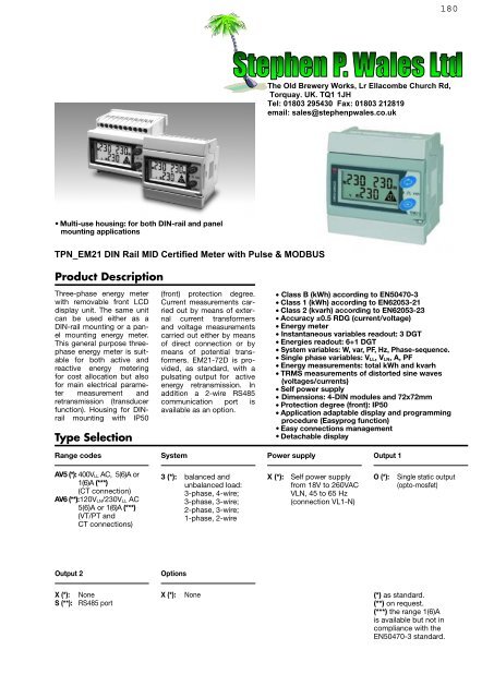
• Multi-use housing: for both <strong>DIN</strong>-rail and panel<br />
mounting applications<br />
Product Description<br />
Energy Management<br />
Energy Meter<br />
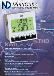
TPN_EM21 <strong>DIN</strong> Rail MID Certified Meter with Pulse & MODBUS<br />
Three-phase energy meter<br />
with removable front LCD<br />
display unit. The same unit<br />
can be used either as a<br />
<strong>DIN</strong>-rail mounting or a panel<br />
mounting energy meter.<br />
This general purpose threephase<br />
energy meter is suitable<br />
for both active and<br />
reactive energy metering<br />
for cost allocation but also<br />
for main electrical parameter<br />
measurement and<br />
retransmission (transducer<br />
function). Housing for <strong>DIN</strong>rail<br />
mounting with IP50<br />
Type Selection<br />
(front) protection degree.<br />
Current measurements carried<br />
out by means of external<br />
current transformers<br />
and voltage measurements<br />
carried out either by means<br />
of direct connection or by<br />
means of potential transformers.<br />
EM21-72D is provided,<br />
as standard, with a<br />
pulsating output for active<br />
energy retransmission. In<br />
addition a 2-wire RS485<br />
communication port is<br />
available as an option.<br />
• Class B (kWh) according to EN50470-3<br />
• Class 1 (kWh) according to EN62053-21<br />
• Class 2 (kvarh) according to EN62053-23<br />
• Accuracy ±0.5 RDG (current/voltage)<br />
• Energy meter<br />
• Instantaneous variables readout: 3 DGT<br />
• Energies readout: 6+1 DGT<br />
• System variables: W, var, PF, Hz, Phase-sequence.<br />
• Single phase variables: V LL, V LN, A, PF<br />
• Energy measurements: total kWh and kvarh<br />
• TRMS measurements of distorted sine waves<br />
(voltages/currents)<br />
• Self power supply<br />
• Dimensions: 4-<strong>DIN</strong> modules and 72x72mm<br />
• Protection degree (front): IP50<br />
• Application adaptable display and programming<br />
procedure (Easyprog function)<br />
• Easy connections management<br />
• Detachable display<br />
Range codes<br />
System<br />
Power supply<br />
Output 1<br />
AV5 (*): 400V LL AC, 5(6)A or<br />
1(6)A (***)<br />
(CT connection)<br />
AV6 (**):120V LN/230V LL AC<br />
5(6)A or 1(6)A (***)<br />
(VT/PT and<br />
CT connections)<br />
3 (*): balanced and<br />
unbalanced load:<br />
3-phase, 4-wire;<br />
3-phase, 3-wire;<br />
2-phase, 3-wire;<br />
1-phase, 2-wire<br />
X (*):<br />
Self power supply<br />
from 18V to 260VAC<br />
VLN, 45 to 65 Hz<br />
(connection VL1-N)<br />
O (*):<br />
Single static output<br />
(opto-mosfet)<br />
Output 2<br />
Options<br />
X (*):<br />
S (**):<br />
None<br />
RS485 port<br />
X (*):<br />
None<br />
(*) as standard.<br />
(**) on request.<br />
(***) the range 1(6)A<br />
is available but not in<br />
compliance with the<br />
EN50470-3 standard.
EM21 72D<br />
Input specifications<br />
Rated inputs System type: 3<br />
Current type<br />
Not isolated (shunt inputs).<br />
Note: the external current<br />
transformers can be connected<br />
to earth individually.<br />
Current range (by CT) AV5 and AV6: 5(6)A. The<br />
“1(6)A” range is available<br />
but not in compliance with<br />
the EN50470-3 standard.<br />
Voltage (direct or by VT/PT) AV5: 400VLL;<br />
AV6: 120/230VLL<br />
Accuracy (Display + RS485) In: see below, Un: see below<br />
(@25°C ±5°C, R.H. ≤60%,<br />
48 to 62 Hz)<br />
AV5 model<br />
In: 5A, Imax: 6A; Un: 160 to<br />
260VLN (277 to 450VLL).<br />
AV6 model<br />
In: 5A, Imax: 6A; Un: 40 to<br />
144VLN (70 to 250VLL).<br />
Current AV5, AV6 models From 0.002In to 0.2In:<br />
±(0.5% RDG +3DGT).<br />
From 0.2In to Imax:<br />
±(0.5% RDG +1DGT).<br />
Phase-neutral voltage In the range Un: ±(0,5%<br />
RDG +1DGT).<br />
Phase-phase voltage In the range Un: ±(1% RDG<br />
+1DGT).<br />
Frequency<br />
Range: 45 to 65Hz;<br />
resolution: ±1Hz<br />
Active power<br />
±(1%RDG +2DGT).<br />
Power Factor<br />
±[0.001+1%(1.000 - “PF<br />
RDG”)].<br />
Reactive power<br />
±(2%RDG +2DGT).<br />
Active energy<br />
class B according to<br />
EN50470-1-3;<br />
class 1 according to<br />
EN62053-21.<br />
Reactive energy<br />
class 2 according to<br />
EN62053-23.<br />
In: 5A, Imax: 6A; 0.1 In:<br />
0.5A.<br />
Start up current: 10mA.<br />
Energy additional errors<br />
Influence quantities<br />
According to EN62053-21,<br />
EN50470-1-3, EN62053-23<br />
Temperature drift<br />
≤200ppm/°C.<br />
Sampling rate<br />
1600 samples/s @ 50Hz,<br />
1900 samples/s @ 60Hz<br />
Display refresh time<br />
1 second<br />
Display<br />
2 lines<br />
1 st line: 7-DGT,<br />
2 nd line: 3-DGT or<br />
1 st line: 3-DGT + 3-DGT,<br />
2 nd line: 3-DGT.<br />
Type<br />
LCD, h 7mm.<br />
Instantaneous variables read-out 3-DGT.<br />
Energies<br />
Overload status<br />
Max. and Min. indication<br />
LEDs<br />
Max frequency<br />
Measurements<br />
Method<br />
Coupling type<br />
Crest factor<br />
Current Overloads<br />
Continuous<br />
For 500ms<br />
Voltage Overloads<br />
Continuous<br />
For 500ms<br />
Current input impedance<br />
5(6)A<br />
Voltage input impedance<br />
Self-power supply<br />
Frequency<br />
Key-pad<br />
Imported Total: 6+1DGT or<br />
7DGT<br />
EEE indication when the<br />
value being measured is<br />
exceeding the “Continuous<br />
inputs overload” (maximum<br />
measurement capacity)<br />
Max. instantaneous variables:<br />
999; energies:<br />
999 999.9 or 9 999 999.<br />
Min. instantaneous variables:<br />
0; energies 0.0.<br />
Red LED (Energy consumption)<br />
0.001 kWh by pulse if CT<br />
ratio x VT ratio is
EM21 72D<br />
Output specifications<br />
Pulse output<br />
Number of outputs 1<br />
Type<br />
Programmable from 0.01 to<br />
9.99 kWh per pulses. Output<br />
connectable to the<br />
energy meters (kWh)<br />
Pulse duration<br />
≥100ms < 120ms (ON),<br />
≥120ms (OFF), according<br />
to EN62052-31.<br />
Output<br />
Static: opto-mosfet.<br />
Load<br />
V ON 2.5 VAC/DC max. 70 mA,<br />
V OFF 260 VAC/DC max.<br />
Insulation<br />
By means of optocouplers,<br />
4000 VRMS output to measuring<br />
inputs.<br />
RS485<br />
Type<br />
Connections<br />
Addresses<br />
Software functions<br />
Multidrop, bidirectional<br />
(static and dynamic variables)<br />
2-wire. Max. distance<br />
1000m, termination directly<br />
on the instrument.<br />
247, selectable by means<br />
of the front keypad<br />
Protocol<br />
Data (bidirectional)<br />
Dynamic (reading only)<br />
Static (reading and writing)<br />
Data format<br />
Baud-rate<br />
Driver input capability<br />
Insulation<br />
MODBUS/JBUS (RTU)<br />
System and phase variables:<br />
see table “List of<br />
variables...”<br />
All the configuration<br />
parameters.<br />
1 start bit, 8 data bit, no<br />
parity,1 stop bit.<br />
9600 bits/s.<br />
1/5 unit load. Maximum<br />
160 transceiver on the<br />
same bus.<br />
By means of optocouplers,<br />
4000 VRMS output to measuring<br />
input.<br />
Password Numeric code of max. 3<br />
digits;<br />
2 protection levels of the<br />
programming data:<br />
1st level<br />
Password “0”, no protection;<br />
2nd level<br />
Password from 1 to 999, all<br />
data are protected<br />
Programming lock<br />
By means of potentiometer<br />
(back-side of the display<br />
module) it is possible to<br />
lock the access to all the<br />
configuration parameters.<br />
System selection<br />
System 3-Ph.n unbalanced load 3-phase (4-wire)<br />
3-phase (3-wire)<br />
System 3-Ph.1 balanced load • 3-phase (3-wire) one current<br />
and 3-phase to phase<br />
voltage measurements.<br />
Note: the phase to phase<br />
voltage is calculated multiplying<br />
by 1.73 the virtual<br />
phase to neutral voltage.<br />
• 3-phase (4-wire) one current<br />
and 3-phase to neutral<br />
voltage measurements.<br />
Note: the phase to phase<br />
voltage is calculated multiplying<br />
by 1.73 the virtual<br />
phase to neutral voltage.<br />
• 3-phase (2-wire) one current<br />
and 1-phase (L1) to<br />
neutral voltage measurement.<br />
System 2-Ph<br />
2-phase (3-wire)<br />
System 1-Ph<br />
1-phase (2-wire)<br />
Transformer ratio<br />
VT (PT) 1.0 to 99.9 / 100 to 999 /<br />
1.00k to 6.00k<br />
CT 1.0 to 99.9 / 100 to 999 /<br />
1.00k to 9.99k / 10.0k to<br />
60.0k.<br />
The maximum power being<br />
measured cannot exceed<br />
210 MW calculated as<br />
maximum input voltage<br />
and current, (see the<br />
“Accuracy” paragraph).<br />
The maximum VT by CT<br />
ratio is 48.600. For MID<br />
complaint applications the<br />
maximum power being<br />
measured is 25 MW.<br />
Displaying<br />
Up to 3 variables per page.<br />
See « Display pages » , 3<br />
different set of variables<br />
available (see « Display<br />
pages ») according to the<br />
metering function being<br />
selected.<br />
Reset<br />
By means of the front keypad:<br />
total energies (kWh,<br />
kvarh).<br />
Easy connection function Wrong phase detection<br />
and displaying. For all the<br />
display selections, both<br />
energy and power measurements<br />
are independent<br />
from the current direction.<br />
The displayed energy is<br />
always “imported”.<br />
Specifications are subject to change without notice EM2172D DS ENG 280708 3
EM21 72D<br />
General specifications<br />
Operating temperature<br />
Storage temperature<br />
Installation category<br />
Insulation (for 1 minute)<br />
Dielectric strength<br />
Noise rejection CMRR<br />
EMC<br />
Electrostatic discharges<br />
Immunity to irradiated<br />
Electromagnetic fields<br />
Burst<br />
Immunity to conducted<br />
disturbances<br />
-25°C to +55°C (-13°F to<br />
131°F) (R.H. from 0 to 90%<br />
non-condensing @ 40°C)<br />
according to EN62053-21<br />
and EN62053-23.<br />
-30°C to +70°C (-22°F to<br />
158°F) (R.H. < 90% noncondensing<br />
@ 40°C)<br />
according to EN62053-21<br />
and EN62053-23.<br />
Cat. III (IEC60664,<br />
EN60664).<br />
4000 VRMS between measuring<br />
inputs and digital<br />
output.<br />
4000 VRMS for 1 minute.<br />
100 dB, 48 to 62 Hz.<br />
According to EN62052-11<br />
15kV air discharge;<br />
Test with current: 10V/m<br />
from 80 to 2000MHz;<br />
Test without any current:<br />
30V/m from 80 to<br />
2000MHz;<br />
On current and voltage<br />
measuring inputs circuit: 4kV<br />
10V/m from 150KHz to<br />
80MHz<br />
Surge<br />
On current and voltage<br />
measuring inputs circuit:<br />
6kV;<br />
Radio frequency suppression According to CISPR 22<br />
Standard compliance<br />
Safety<br />
Metrology<br />
Pulse output<br />
Approvals<br />
Connections<br />
Cable cross-section area<br />
Housing<br />
Dimensions (WxHxD)<br />
Material<br />
Mounting<br />
Protection degree<br />
Front<br />
Screw terminals<br />
Weight<br />
IEC60664, IEC61010-1<br />
EN60664, EN61010-1<br />
EN62052-11<br />
EN62053-21, EN62053-23,<br />
EN50470-3<br />
<strong>DIN</strong>43864, IEC62053-31<br />
CE<br />
Screw-type<br />
2.4 x 3.5 mm<br />
Min./Max. screws tightening<br />
torque: 0.4 Nm / 0.8 Nm<br />
72 x 72 x 65 mm<br />
Noryl PA66,<br />
self-extinguishing: UL 94 V-0<br />
Panel and <strong>DIN</strong>-rail<br />
IP50<br />
IP20<br />
Approx. 400 g (packing<br />
included)<br />
Power supply specifications<br />
Self power supply<br />
18 to 260VAC (48-62Hz).<br />
Across input “VL1” and “N”<br />
Power consumption<br />
≤2VA/1W<br />
Insulation between inputs and outputs<br />
Measuring Inputs Opto-Mosfet output Communication port Self power supply<br />
Measuring Inputs - 4kV 4kV 0kV<br />
Opto-Mosfet output 4kV - - 4kV<br />
Communication port 4kV - - 4kV<br />
Self power supply 0kV 4kV 4kV -<br />
NOTE: all the models have, mandatorily, to be connected to external current transformers.<br />
4 Specifications are subject to change without notice EM2172D DS ENG 280708
EM21 72D<br />
Accuracy (According to EN50470-3 and EN62053-23)<br />
kWh, accuracy (RDG) depending on the current<br />
kvarh, accuracy (RDG) depending on the current<br />
Percentage error limits for class index B<br />
Percentage error limits<br />
+1,5%<br />
+1%<br />
+2,5%<br />
+2%<br />
0%<br />
0%<br />
-1%<br />
-1,5%<br />
-2%<br />
-2,5%<br />
PF=1<br />
0.05A(I min)<br />
0.25A(I tr)<br />
5A (I n)<br />
6A (I max)<br />
sinϕ=1<br />
0.1A<br />
0.25A<br />
5A (I n)<br />
6A (I max)<br />
PF=L0.5<br />
to C0.8<br />
0.25A(I tr)<br />
5A (I n)<br />
Accuracy limits (Active energy)<br />
Start-up current: 10mA<br />
6A (I max)<br />
sinϕ=0.5<br />
0.25A<br />
0.5A<br />
5A (I n)<br />
Accuracy limits (Reactive energy)<br />
Start-up current: 10mA<br />
6A (I max)<br />
EN50470-3 compliance<br />
Accuracy<br />
0.9 Un ≤ U ≤ 1.1 Un;<br />
0.98 fn ≤ f ≤ 1.02 fn;<br />
fn: 50 or 60Hz;<br />
cosϕ: 0.5 inductive to 0.8<br />
capacitive.<br />
Class B<br />
I st: 0.01A;<br />
I min: 0.05A;<br />
I tr: 0.25A;<br />
Operating temperature<br />
EMC compliance<br />
I n: 5A<br />
I max: 6A.<br />
-25°C to +55°C (-13°F to<br />
131°F) (R.H. from 0 to 90%<br />
non-condensing @ 40°C)<br />
E2<br />
Used calculation formulas<br />
Phase variables<br />
Instantaneous effective voltage<br />
System variables<br />
Equivalent three-phase voltage<br />
Three-phase power factor<br />
(TPF)<br />
Instantaneous active power<br />
Voltage asymmetry<br />
Energy metering<br />
Instantaneous power factor<br />
Instantaneous effective current<br />
Instantaneous apparent power<br />
Instantaneous reactive power<br />
Three-phase active power<br />
Three-phase apparent power<br />
Where:<br />
i= considered phase (L1, L2 or L3)<br />
P= active power; Q= reactive power;<br />
t 1, t 2 =starting and ending time points<br />
of consumption recording; n= time<br />
unit;∆t= time interval between two<br />
successive power consumptions;<br />
n 1, n 2 = starting and ending discrete<br />
time points of consumption recording<br />
Specifications are subject to change without notice EM2172D DS ENG 280708 5
EM21 72D<br />
List of the variables that can be connected to:<br />
• RS485 communication port<br />
• Pulse outputs (only “energies”)<br />
No<br />
Variable<br />
1-ph.<br />
sys.<br />
2-ph.<br />
sys.<br />
3-ph. 4-wire<br />
balanced<br />
system<br />
3-ph. 3-wir<br />
balanced<br />
system<br />
(x) = available<br />
(o) = not available (zero indication on the display)<br />
(1) = Variable available only through the serial communication port RS485<br />
3-ph. 4-wire<br />
unbalanced<br />
system<br />
3-ph. 3-wir<br />
unbalanced<br />
system<br />
Notes<br />
1 kWh x x x x x x Total<br />
2 kvarh x x x x x x Total<br />
3 V L-N sys (1) o x x x x x sys=system (∑)<br />
4 V L1 x x x x x x<br />
5 V L2 o x x x x x<br />
6 V L3 o o x x x x<br />
7 V L-L sys (1) o x x x x x sys=system (∑)<br />
8 V L1-2 o x x x x x<br />
9 V L2-3 o o x x x x<br />
10 V L3-1 o o x x x x<br />
11 A L1 x x x x x x<br />
12 A L2 o x x x x x<br />
13 A L3 o o x x x x<br />
14 VA sys (1) x x x x x x sys=system (∑)<br />
15 VA L1 (1) x x x x x x<br />
16 VA L2 (1) o x x x x x<br />
17 VA L3 (1) o o x x x x<br />
18 var sys x x x x x x sys=system (∑)<br />
19 var L1 (1) x x x x x x<br />
20 var L2 (1) o x x x x x<br />
21 var L3 (1) o o x x x x<br />
22 W sys x x x x x x sys=system (∑)<br />
23 W L1 (1) x x x x x x<br />
24 W L2 (1) o x x x x x<br />
25 W L3 (1) o o x x x x<br />
26 PF sys x x x x x x sys=system (∑)<br />
27 PF L1 x x x x x x<br />
28 PF L2 o x x x x x<br />
29 PF L3 o o x x x x<br />
30 Hz x x x x x x<br />
31 Phase sequence o o x x x x<br />
Display pages<br />
No<br />
1st variable<br />
(1 st half-line)<br />
2nd variable<br />
(2 nd half-line)<br />
3rd variable<br />
(2nd line)<br />
6 Specifications are subject to change without notice EM2172D DS ENG 280708<br />
Note<br />
Applications<br />
A B C<br />
Phase sequence<br />
The phase sequence tringle appears in<br />
any page only if there is a phase reverse<br />
x x x<br />
1 Total kWh W sys x x x<br />
2 Total kvarh kvar sys x x<br />
3 PF sys Hz<br />
Indication of C, -C, L, -L depending on<br />
the quadrant<br />
x x x<br />
4 PF L1 PF L2 PF L3<br />
Indication of C, -C, L, -L depending on<br />
the quadrant<br />
x<br />
5 A L1 A L2 A L3 x<br />
6 V L1-2 V L2-3 V L3-1 x<br />
7 V L1 V L2 V L3 x
EM21 72D<br />
Additional available information on the display<br />
Type 1st line 2nd line note<br />
Meter information 1 Y. 2007 r.A0 Year of production and firmware release<br />
Meter information 2 value LEd (kWh) KWh per pulse of the LED<br />
Meter information 3 SYS [3P.n] value System type and connection type<br />
Meter information 4 Ct rAt. value Current transformer ratio<br />
Meter information 5 Ut rAt. value Voltage transformer ratio<br />
Meter information 6 PuLSE (kWh) value Pulse output: kWh per pulse<br />
Meter information 7 Add value Serial communication address<br />
List of selectable applications<br />
Description<br />
Notes<br />
A Active energy meter Active energy measurement with some minor parameters<br />
B Active and reactive energy meter Active and reactive energy measurement with some minor parameters<br />
C Full set of variables Full set of available variables can be displayed<br />
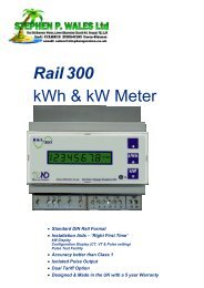
One instrument with double mounting capability<br />
By means of the patented detachable display it is possible<br />
to configure the same instrument either as a panel<br />
mounting meter or...<br />
... as <strong>DIN</strong>-rail mounting meter.<br />
Specifications are subject to change without notice EM2172D DS ENG 280708 7
EM21 72D<br />
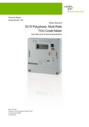
Wiring diagrams<br />
(6A) Self power supply, system type selection: 3P.n<br />
3-ph, 4-wire, unbalanced load Fig. 1<br />
3-ph, 4-wire, unbalanced load Fig. 2<br />
6A inputs<br />
V inputs<br />
9 8 7 10 6 5 4 3 2 1 9 8 7 10 6 5 4 3 2 1<br />
RS485<br />
Static output<br />
3-CT connection<br />
3-CT and 3-VT/PT connections<br />
(6A) System type selection: 3P.n<br />
3-ph, 3-wire, unbalanced load Fig. 3<br />
3-ph, 3-wire, unbalanced load Fig. 4<br />
3-ph, 3-wire, unbalanced load Fig. 5<br />
9 8 7 10 6 5 4 3 2 1 9 8 7 10 6 5 4 3 2 1 9 8 7 10 6 5 4 3 2 1<br />
(*) (*) (*)<br />
3-CT connection<br />
3-CT and 2-VT/PT connections<br />
2-CT connections (ARON)<br />
(6A) Self power supply, system type selection: 3P.1<br />
3-ph, 3-wire, unbalanced load Fig. 6<br />
3-ph, 3-wire, balanced load Fig. 7<br />
1-CT connection<br />
3-ph, 3-wire, balanced load Fig. 8<br />
9 8 7 10 6 5 4 3 2 1 9 8 7 10 6 5 9 8 7 10 6 5<br />
(*) (*)<br />
2-CT and 2-VT/PT connections ARON<br />
NOTE: a 2-wire connection for voltage measurement<br />
is available accross 9 and 10 .<br />
1-CT and 2-VT/PT connections<br />
(*) NOTE: For a correct power supply of the instrument, the neutral must always be connected.<br />
8 Specifications are subject to change without notice EM2172D DS ENG 280708
EM21 72D<br />
Wiring diagrams<br />
(6A) System type selection: 2P<br />
2-ph, 3-wire Fig. 9<br />
2-ph, 3-wire Fig. 10<br />
(6A) System type selection: 1P<br />
1-ph, 2-wire Fig. 11<br />
9 8 10 6 5 4 3 9 8 10 6 5 4 3 9 10 6 5<br />
2-CT connection<br />
2-CT and 2-VT/PT connections<br />
1-CT connection<br />
(6A) System type selection: 1P<br />
1-ph, 2-wire Fig. 12<br />
Static output wiring diagram<br />
Opto-mosfet<br />
9 10 6 5<br />
VDC/AC<br />
17 18<br />
1-CT and 1-VT connections<br />
VDC/AC supply<br />
RS485 port wiring diagram<br />
RS485 port<br />
16<br />
16<br />
B+<br />
15<br />
B+<br />
15<br />
B+<br />
A-<br />
14<br />
A-<br />
14<br />
A-<br />
13<br />
13<br />
RS485 NOTE: additional devices provided with RS485 are connected as per the picture above. The termination of the serial<br />
output is carried out only on the last instrument of the network, by means of a jumper between (B+) and (T).<br />
Specifications are subject to change without notice EM2172D DS ENG 280708 9
EM21 72D<br />
Front panel description<br />
5<br />
3<br />
4<br />
1<br />
2<br />
1<br />
4<br />
1. Keypad<br />
To program the configuration parameters and scroll the<br />
variables on the display.<br />
2. Pulse output LED<br />
Red LED blinking proportional to the energy being<br />
measured.<br />
3. Display<br />
LCD-type with alphanumeric indications to display all the<br />
measured variables.<br />
4. Connections<br />
Screw terminal blocks for instrument wiring.<br />
5. Green LED<br />
Lit when power supply is available<br />
Dimensions (<strong>DIN</strong> configuration)<br />
Dimensions and panel cut out (72x72 panel mounting configuration)<br />
68x68mm<br />
-0 +0.7mm<br />
10 Specifications are subject to change without notice EM2172D DS ENG 280708