
Create successful ePaper yourself
Turn your PDF publications into a flip-book with our unique Google optimized e-Paper software.
Alfred Evert 2008-11-30<br />
<strong>07.12.</strong> <strong>Summary</strong><br />
Free Energy by Centrifugal Force<br />
Researching possibilities for Free Energy mostly starts with pure mechanic systems. There are lots of<br />
experiments with un-balanced ´wheels´, i.e. for using gravity force. However lever-arm-law is<br />
absolutely strong. So also most of my proposals e.g. of ´Bessler-Wheels´ are dominated by wishful<br />
thinking - with some exceptions e.g. that ´Rhön-Rad´ which still might function (however nobody did<br />
build up to now). In principle however I consider fluid-machines more suitable, because liquids allow<br />
variable shape of mass and gases in<br />
addition allow variable density.<br />
Liquids are thousand times more dense<br />
than gases, so devices could be build<br />
smaller when using water or oil as working<br />
medium. The shorter the radius, the<br />
stronger centrifugal forces affect. These<br />
enormous forces are ´annoying´ at most<br />
applications, however by suitable<br />
arrangement should result corresponding<br />
benefit. At previous chapter 07.05.<br />
Centrifugal-Thrust-Engine some proposals<br />
are discussed.<br />
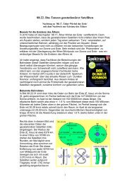
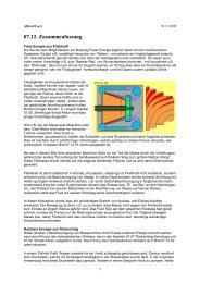
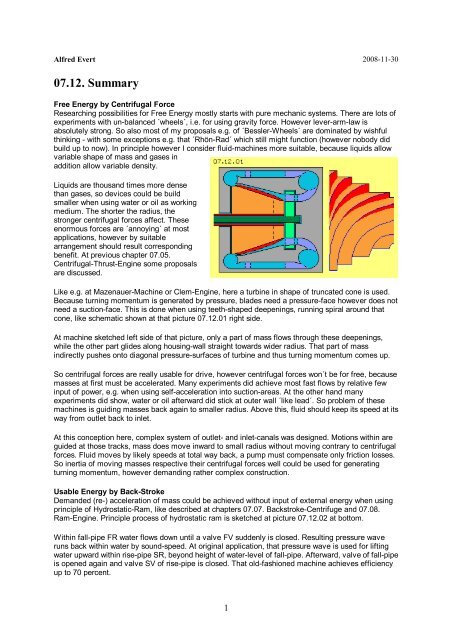
Like e.g. at Mazenauer-Machine or Clem-Engine, here a turbine in shape of truncated cone is used.<br />
Because turning momentum is generated by pressure, blades need a pressure-face however does not<br />
need a suction-face. This is done when using teeth-shaped deepenings, running spiral around that<br />
cone, like schematic shown at that picture <strong>07.12.</strong>01 right side.<br />
At machine sketched left side of that picture, only a part of mass flows through these deepenings,<br />
while the other part glides along housing-wall straight towards wider radius. That part of mass<br />
indirectly pushes onto diagonal pressure-surfaces of turbine and thus turning momentum comes up.<br />
So centrifugal forces are really usable for drive, however centrifugal forces won´t be for free, because<br />
masses at first must be accelerated. Many experiments did achieve most fast flows by relative few<br />
input of power, e.g. when using self-acceleration into suction-areas. At the other hand many<br />
experiments did show, water or oil afterward did stick at outer wall ´like lead´. So problem of these<br />
machines is guiding masses back again to smaller radius. Above this, fluid should keep its speed at its<br />
way from outlet back to inlet.<br />
At this conception here, complex system of outlet- and inlet-canals was designed. Motions within are<br />
guided at those tracks, mass does move inward to small radius without moving contrary to centrifugal<br />
forces. Fluid moves by likely speeds at total way back, a pump must compensate only friction losses.<br />
So inertia of moving masses respective their centrifugal forces well could be used for generating<br />
turning momentum, however demanding rather complex construction.<br />
Usable Energy by Back-Stroke<br />
Demanded (re-) acceleration of mass could be achieved without input of external energy when using<br />
principle of Hydrostatic-Ram, like described at chapters 07.07. Backstroke-Centrifuge and 07.08.<br />
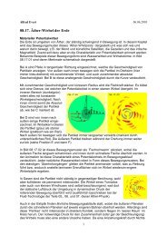
Ram-Engine. Principle process of hydrostatic ram is sketched at picture <strong>07.12.</strong>02 at bottom.<br />
Within fall-pipe FR water flows down until a valve FV suddenly is closed. Resulting pressure wave<br />
runs back within water by sound-speed. At original application, that pressure wave is used for lifting<br />
water upward within rise-pipe SR, beyond height of water-level of fall-pipe. Afterward, valve of fall-pipe<br />
is opened again and valve SV of rise-pipe is closed. That old-fashioned machine achieves efficiency<br />
up to 70 percent.<br />
1
At previous Backstroke-Centrifuge respective Ram-<br />
Engine (e.g. like sketched upside of that picture by<br />
longitudinal cross-sectional view), opening and closing<br />
of valves is organized like ´revolving valve´. Openings of<br />
rotor glide along housing wall which by parts shows<br />
closed surface, by parts has openings. When openings<br />
match, water flows off rotor forward-outward. When<br />
opening of rotor comes to closed part of housing wall,<br />
flow abruptly is stopped, so previous vehement backstroke<br />
occurs.<br />
Pressure of flow is mirrored, so pressure wave is<br />
directed forward-inward. Also within water, a pressure<br />
wave represents short compression, which afterward<br />
relaxes. So there is a short motion forward, followed by<br />
standstill or even backward motion. At hydraulic ram,<br />
that backstroke is lifting water within rise-pipe resp.<br />
water within fall-pipe also is pushed some upward.<br />
Finally however, that wave-power ´disappears´ at both<br />
water-surfaces. Now here, that pressure wave is running<br />
around within rotor. Each pressure wave pushes water<br />
some forward in turning sense. Each following pressure<br />
wave hits onto water already rotating. Thus within short<br />
time, all water within rotor becomes rotating,<br />
continuously pushed forward by pulsating pressure<br />
waves. So now centrifugal forces come up and water is<br />
pressed along cone-shaped walls towards wider radius.<br />
Finally, water flows off rotor-openings by pulsating waves into areas of less environmental pressure.<br />
Thus within these machines, inertia is used in shape of centrifugal forces, resulting flow along diagonal<br />
arranged walls. At least by parts, that flow is transferred into turning momentum by suitable turbineblades.<br />
If at the other hand that flow is stopped, deceleration occurs within thousandth part of second,<br />
resulting huge forces. Periodic pressure waves running around within rotor accelerate water in turning<br />
sense. Corresponding experiments already approved<br />
these theoretic considerations. However still problem is<br />
optimum shape and arrangement of turbine-blades.<br />
Blade-less Ram-Engine<br />
Other experiments did show, turbines without blades<br />
often are best solution, because flow becomes<br />
decelerated only moderately and turning momentum is<br />
generated only by friction at surface rather smooth. As<br />
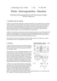
an addition to previous machines, picture <strong>07.12.</strong>03<br />
shows a ram-engine without blades.<br />
At vertical shaft (dark red) a turbine T (light red) is<br />
installed. Turbine is build by cone-shaped core and a<br />
hollow truncated cone. Upside both constructional<br />
elements are connected e.g. by two rods, which are<br />
little bit inclined, so working as pump P (light green),<br />
pushing water downward. At bottom both constructional<br />
elements are connected by diagonal disk, which shows<br />
openings, through which water can flow off turbine.<br />
Opposite to that turbine-bottom is positioned<br />
corresponding disk of housing, which also shows<br />
openings, however partly builds closed surface. While<br />
turbine-openings glide along housing-disk, temporary<br />
an open valve OV (right) or a closed valve GV (left) is<br />
2
given. Water thus temporary will flow downward-outward based on centrifugal forces, like marked at A.<br />
At the other hand, temporary will occur back-stroke B, within rotor running around in turning sense of<br />
system.<br />
That back-stroke pressure-wave also runs upward within that hollow cone and is mirrored downward<br />
again. At a whole thus water within rotor becomes accelerated in turning sense. When valves are<br />
open, water vehemently are pushed off by mirrored pressure wave. Openings of turbine and of<br />
housing as well must have smooth edges, e.g. like sketched quite downside at this picture. So this<br />
turbine has null blades, but fast turning water by friction at outer walls is generating usable turning<br />
momentum.<br />
Laval-Nozzles at Wind-Tower<br />
Already at chapter 06.03. Ultrasound-Engine of previous part, motion processes were discussed<br />
resulting ultrasound-fast flows by Laval-Nozzles. Within bottlenecks occur increased number of<br />
multiple-collisions, where e.g. two molecules transfer their kinetic energy onto third molecule same<br />
time. That ´racer´ thus flies by over-size speed into following wide outlet area and comes forward long<br />
distances within that relative void. Both energy-delivering molecules stay back within bottleneck by<br />
relative slow movements. These ´stationers´ show few resistance for following collisions, thus have<br />
good chance to become next ´racers´, flying through outlet with some delay however fast speed.<br />
Efficiency of these Laval-Nozzles is approved at many<br />
technical applications. Also diverse experiments to<br />
proposals of previous chapters did result flows of high<br />
speed by input of few external energy. At chapter 07.06.<br />
Wind-Tower-Current-Generator diverse proposals were<br />
discussed for generating mechanic turning momentum<br />
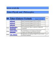
by most simple technology. Picture <strong>07.12.</strong>04 shows an<br />
example of a Wind-Tower by cross-sectional view.<br />
Pump P (green) is simple round cylinder, pulling air into<br />
turning sense (left turning) only by friction at its surface.<br />
That blade-less pump naturally is turned easy. Turbine<br />
T (red) is a hollow cylinder with diameter some wider. If<br />
turbine would have only simple round surface, turbine<br />
would also become turning via air movements. However<br />
there would be ´slip´ and turning momentum could not<br />
be transferred in total.<br />
Now however that surface is shaped that kind, bottlenecks are build and each bottleneck is followed<br />
by wider area. In front of bottleneck, air is dammed up, i.e. turning momentum is transferred onto<br />
turbine. Within bottleneck exists high density, so multiple-collisions occur frequently. Resulting fast<br />
particles fly into following relative void of wider area, finally hitting onto diagonal wall of next<br />
bottleneck, i.e. resulting additional strong thrust.<br />
Generally, mass-throughput in front of and behind of Laval-Nozzle naturally is of same size. However<br />
kinetic energy of fast flow essentially is increased. That energy by parts is transferred via friction onto<br />
surfaces of turbine and also of pump. At the other hand, these fast particles press into next bottleneck.<br />
Static pressure of dense air there pushes onto diagonal turbine-wall. By that arrangement, thus<br />
acceleration-effect of Laval-Nozzle is used by simple technique. However it will demand many<br />
experiments to find best contours and optimum distances at most suitable revolutions.<br />
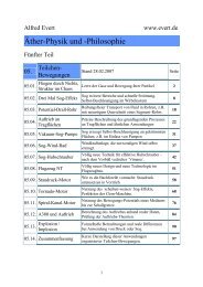
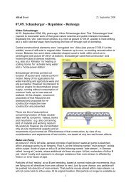
Schauberger-Repulsine Re-Design<br />
Behind bottleneck of Laval-Nozzle, particles fly with high speed (even by ultra-sound-speed), however<br />
only few particles each time-unit. So within wide area of outlet exists relative few density. That fast and<br />
thin flow is ideal for merging-in ´wrong-air´ analogue to water-jet-pump. Within inlet aside and direct<br />
behind bottleneck, particles purely by chance are pushed into direction of outlet, based on quite<br />
normal molecular movements. Also these particles move at least by sound-speed, realiter by some<br />
500 m/s. As relative few particles from bottleneck fly even faster into likely directions, few resistance<br />
exists for these additional particles. So behind bottleneck of Laval-Nozzle, not only super-fast flow is<br />
generated but also increased mass-throughput is achieved.<br />
3
´Classic´ example for alternative flowscience<br />
respective research for Free<br />
Energy is Schauberger´s Repulsine.<br />
Many considerations and assumptions<br />
exist concerning function of that machine,<br />
also concerning material used. After long<br />
researches of my Fluid-Technology,<br />
mostly based on ideas of Schauberger,<br />
and also based on ´strange´<br />
appearances of diverse experiments,<br />
now years later I studied that machine<br />
once again. These wave-shaped disks<br />
represent narrowings and extensions<br />
running all around - and via slots also<br />
additional air is allowed to flow into canal<br />
between both disks.<br />
In order to realize that acceleration-effect of Laval-Nozzle inclusive increased mass-throughput by<br />
most simple technique, I made proposals for re-design of Schauberger-Repulsine, like e.g. sketched at<br />
picture <strong>07.12.</strong>05. Turbine (red) should be build symmetric, so additional air can be included from both<br />
sides. Near system axis, at both sides should be installed pumps (green), guiding air into first narrow<br />
area (dark blue). Direct behind bottleneck, additional air flows in from aside into that wider space (light<br />
blue). Both flows are dammed up at next bottleneck.<br />
Inside, air is pulled into turning sense by friction at surfaces. Air thus leaves bottleneck in direction<br />
outward-forward. As particle there show increased speed, they fly faster forward than rotor is turning.<br />
From bottleneck to bottleneck speed becomes faster and faster. Also that additional air can follow<br />
movements up to sound-speed without problem, flying fast by ´own drive´ (of just normal molecular<br />
movement). These fast masses finally push turbine forward in turning send, by friction at surfaces,<br />
especially in front of bottlenecks. Additional turning momentum is achieved by redirection of fast flow<br />
by some blades at outer border of turbine.<br />
It´s reported by witnesses, Schauberger Repulsine did crash through roof of workshop and did fly up<br />
and away. In spite of many efforts that machine however could not be rebuild functioning. Previous<br />
redesign consequently is reduced at the one hand on acceleration-effect of Laval-Nozzles and at the<br />
other hand on principle of water-jet-pumps. Both functions are known and approved, so reconstruction<br />
based on these principles should finally<br />
result working Repulsine.<br />
Typhoon within Pipe<br />
Absolute clear appearance is also that selfacceleration<br />
of whirlwinds. Relative fast<br />
flow exists at centre and additional air from<br />
wide environment tangential flows inward.<br />
At centre thus exists relative few static<br />
pressure and ambient high static pressure<br />
compresses and accelerates that vortex<br />
system.<br />
Most strong influx comes up along ground<br />
and thus corresponding masses of air must<br />
flow off sideward at top of vortex. That<br />
effect of self-acceleration of potentialvortices<br />
should also be realized by<br />
technical devices.<br />
At chapter 07.10. Typhoon-Engine an<br />
especially compact construction was<br />
presented, e.g. like shown at picture<br />
<strong>07.12.</strong>06 upside by longitudinal cross-<br />
4
sectional view. Air is pressed into that system and accelerated in turning sense by inlet-pump EP<br />
(green, left side), and at the other hand, air is sucked off system by outlet-pump AP (green, right side).<br />
Via backflow-area R air flows back towards inlet-area.<br />
In the middle a turbine T (red) is installed, around which air is turning. Turbine is cone-shaped so air<br />
becomes faster turning towards thin end respective outlet. Rotation is accelerated by sideward influx E<br />
from backflow-area. Around that turbine could also be installed ´nozzle-disks´ DS of housing.<br />
According to Laval-Nozzles some bottlenecks are build between these disks and turbine-surface, so<br />
that rotating forward-inward moving flow once more is accelerated. Usable turning momentum is<br />
generated by friction of air at turbine-surfaces or by blades at turbine-outlet.<br />
The ´Rockwell-Scientific-Research L.L.C.´ presented at internet ´The Advanced Aerodynamic Air<br />
Turbine Engine AATE´ and a photo of that website is shown at this picture at bottom. That engine is<br />
supposed to be based on Schauberger´s considerations for vortex systems, at the other hand vague<br />
statements indicate that machine well could function by previous mentioned techniques.<br />
At any case that outlet-pump produces relative void into which air particles fall by just normal<br />
molecular movements. Instead of normal chaotic motions, structured flows are generated, here fast<br />
rotation at narrow space. Given energy of molecular motions thus temporary is transferred into kinetic<br />
flow-energy, via turning momentum available for external uses (an alternative interpretation see<br />
below).<br />
Interaction with Space-Energy<br />
Well known are experiments of noted laboratories, where fast rotating masses clearly did show loss of<br />
weight and other strange appearances affecting through walls and ceilings. Also some experiments to<br />
my proposals (like other explorers) did result appearances which can not be explained by pure fluidmechanics.<br />
There must have come up any ´coupling with space-energy´ (respective ´zero-pointenergy´<br />
or a ´torsion-field´). For me, no abstract ´energy´ nor abstract ´field´ exists but only real<br />
substance called ether in shape of part-less and thus gap-less plasma. All material appearances,<br />
forces and fields etc. only can be vortices of ether<br />
within ether.<br />
However, within that gapless plasma is not possible<br />
any kind of motion but in principle only swinging<br />
movements at circled tracks can exist, by huge<br />
number of multiple overlaying pattern. Basic motion<br />
pattern are ´Potential-Vortex-Clouds´ and their<br />
principle process of movements is visualized at this<br />
animation.<br />
That pattern appears by most different size, from spiral-galaxy to sun-systems und also e.g. as<br />
electron. Essential motion is swinging inward/outward and same time upward/downward. At equator<br />
that swinging motion is running at an inclined plane.<br />
Free Ether is continuous motion by numberless overlays, thus is moving at ´confusing´ tracks (which I<br />
called ´spiral-cluster-tracks´), however at most small radius, thus in shape of ´fine vibrations´. At a<br />
whole, Free Ether keeps its location within space. Opposite, Bound Ether is local motion pattern at<br />
longer stretched tracks, thus in shape of ´coarse swinging´. Material parts of air or of rotor are such<br />
coarse vortex-systems and their vortex-structures wander through nearby ´stationary´ Free Ether.<br />
If material particles are moving steady at likely tracks, also Free Ether of that region takes that<br />
movement pattern, at least by parts. At the other hand, such general ´ether-flow´ naturally affects<br />
wandering of local vortex-systems drifting within. If now one wants to establish certain interaction<br />
between material particles and ether by itself, one must chose ´very common´ motion pattern, e.g. in<br />
shape of previous potential-vortex-cloud respective advantageous its motion pattern around equator.<br />
Ether-conform Swinging<br />
Chapter 07.11. Torsionfield-Generator shows some rotors which can produce that advantageous<br />
shape of motions. Picture <strong>07.12.</strong>08 schematic shows their basic design by longitudinal cross-sectional<br />
view.<br />
5
That new understanding and new points of view could also explain some other ´mysterious´ effects<br />
e.g. of electro-static devices, especially Testatika. If Carl Tilley really was able to produce surplus<br />
current, his generators probably could have used also that technology. Most interesting now is<br />
previous Air-Turbine-Engine (picture <strong>07.12.</strong>06 bottom), where decisive constructional element is<br />
covered by black sheet - hiding probably previous coil. That machine also is called ´The Crystal Ion´ -<br />
and ´ionised´ air (´turned-up ether-conform´) well could be transferred into electric current. So that Air-<br />
Vortex-Engine might not be constructed for producing mechanic turning momentum, but for directly<br />
producing electric current, analogue to previous considerations).<br />
Outlook<br />
That final part 07. Fluid-Machines once more did show some possibilities for using Free Energy based<br />
on fluid movements. That final <strong>07.12.</strong> <strong>Summary</strong> once more did show some essential aspects. Anyhow,<br />
these three parts of Fluid-Technology were intended only as an excursus into world of material parts,<br />
however these items got extended two long years. Probably I was able to contribute some new<br />
aspects to common flow-science, e.g. concerning theory of lift, difference of suction and pressure<br />
applications, generating ordered flows or about motion processes of Laval-Nozzles and some more.<br />
I pointed out designs of machines should consequently rebuild these effects, by which energy of<br />
normal molecular motions become usable for external benefits. Meanwhile, many of my claims were<br />
approved by corresponding experiments without any doubts, however - by my state of knowledge - no<br />
complete running machine is available or even ready for sale. I can contribute nothing else than these<br />
multiple considerations and clues for new fluid-technologies. I hope these ideas become realized by<br />
other people with corresponding knowledge and abilities and capacities.<br />
That last chapter 07.11. Torsion-Field-Generator already did leave borders of pure fluid-mechanics<br />
and made up new considerations to ether-background of all material resp. physical appearances. Also<br />
here I only can hope, these most interesting interactions between material parts and ether movements<br />
inclusive electric charge and current might stimulate competent experts who like to experiment and<br />
research these strange aspects. I well know, for most people it´s rather hard to believe, real world is<br />
nothing else than somehow swinging plasma. Nevertheless that world-view might help explaining<br />
some phenomena and that understanding is decisive for building previous technical ether-bases<br />
devices - like future machines more efficient in general will only be possible if based on such etherconform<br />
processes.<br />
From now, I will publish exclusively items concerning ether. Just at that last chapter, many subjects<br />
were mentioned only in brief, which now demand detailed descriptions (e.g. gravity and inertia, sun<br />
and planets, electric- and earth-magnetism, charge and current, electron and hydrogen resp. atoms in<br />
general). However first item will show, how membranes are build by ether, i.e. a most important<br />
appearance, by view of that swinging plasma.<br />
Naturally, however some later, I´ll publish further proposals for Free Energy or other ether-conform<br />
constructions. However I hope, meanwhile any machine based on fluid-mechanics will bring real<br />
solution for energy- and environment-problems - or even previous ether-based machines.<br />
Evert / 2008-11-30<br />
7