
Create successful ePaper yourself
Turn your PDF publications into a flip-book with our unique Google optimized e-Paper software.
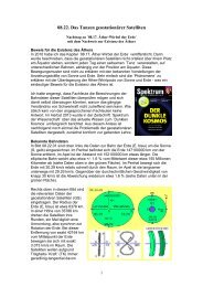
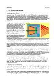
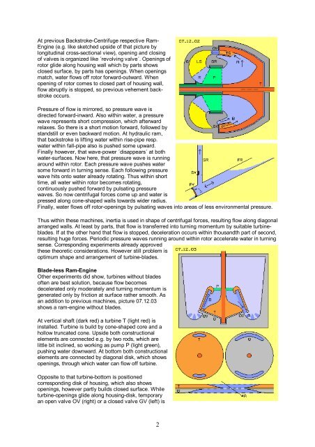
At previous Backstroke-Centrifuge respective Ram-<br />
Engine (e.g. like sketched upside of that picture by<br />
longitudinal cross-sectional view), opening and closing<br />
of valves is organized like ´revolving valve´. Openings of<br />
rotor glide along housing wall which by parts shows<br />
closed surface, by parts has openings. When openings<br />
match, water flows off rotor forward-outward. When<br />
opening of rotor comes to closed part of housing wall,<br />
flow abruptly is stopped, so previous vehement backstroke<br />
occurs.<br />
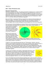
Pressure of flow is mirrored, so pressure wave is<br />
directed forward-inward. Also within water, a pressure<br />
wave represents short compression, which afterward<br />
relaxes. So there is a short motion forward, followed by<br />
standstill or even backward motion. At hydraulic ram,<br />
that backstroke is lifting water within rise-pipe resp.<br />
water within fall-pipe also is pushed some upward.<br />
Finally however, that wave-power ´disappears´ at both<br />
water-surfaces. Now here, that pressure wave is running<br />
around within rotor. Each pressure wave pushes water<br />
some forward in turning sense. Each following pressure<br />
wave hits onto water already rotating. Thus within short<br />
time, all water within rotor becomes rotating,<br />
continuously pushed forward by pulsating pressure<br />
waves. So now centrifugal forces come up and water is<br />
pressed along cone-shaped walls towards wider radius.<br />
Finally, water flows off rotor-openings by pulsating waves into areas of less environmental pressure.<br />
Thus within these machines, inertia is used in shape of centrifugal forces, resulting flow along diagonal<br />
arranged walls. At least by parts, that flow is transferred into turning momentum by suitable turbineblades.<br />
If at the other hand that flow is stopped, deceleration occurs within thousandth part of second,<br />
resulting huge forces. Periodic pressure waves running around within rotor accelerate water in turning<br />
sense. Corresponding experiments already approved<br />
these theoretic considerations. However still problem is<br />
optimum shape and arrangement of turbine-blades.<br />
Blade-less Ram-Engine<br />
Other experiments did show, turbines without blades<br />
often are best solution, because flow becomes<br />
decelerated only moderately and turning momentum is<br />
generated only by friction at surface rather smooth. As<br />
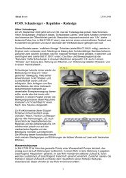
an addition to previous machines, picture <strong>07.12.</strong>03<br />
shows a ram-engine without blades.<br />
At vertical shaft (dark red) a turbine T (light red) is<br />
installed. Turbine is build by cone-shaped core and a<br />
hollow truncated cone. Upside both constructional<br />
elements are connected e.g. by two rods, which are<br />
little bit inclined, so working as pump P (light green),<br />
pushing water downward. At bottom both constructional<br />
elements are connected by diagonal disk, which shows<br />
openings, through which water can flow off turbine.<br />
Opposite to that turbine-bottom is positioned<br />
corresponding disk of housing, which also shows<br />
openings, however partly builds closed surface. While<br />
turbine-openings glide along housing-disk, temporary<br />
an open valve OV (right) or a closed valve GV (left) is<br />
2