RP-01638
RP-01638
RP-01638

Create successful ePaper yourself
Turn your PDF publications into a flip-book with our unique Google optimized e-Paper software.
ARCHIV<br />
SHA<strong>RP</strong><br />
no. 1
The International Development Research Centre is a public<br />
corporation created by the Parliament of Canada in 1970 to<br />
support research designed to adapt science and technology to the<br />
needs of developing countries. The Centre's activity is concentrated<br />
in five sectors; agriculture, food and nutrition sciences;<br />
health sciences; information sciences; social sciences; and<br />
communications. IDRC is financed solely by the Parliament of<br />
Canada; its policies, however, are set by an international Board<br />
of Governors. The Centre's headquarters are in Ottawa, Canada.<br />
Regional offices are located in Africa, Asia, Latin America, and<br />
the Middle East.<br />
©International Development Research Centre 1982<br />
Postal Address: Box 8500, Ottawa, Canada K1G 3H9<br />
Head Office: 60 Queen Street, Ottawa, Canada<br />
Sharp, D.<br />
Graham, M.<br />
IDRC-204e<br />
Village handpump technology : research and evaluation in Asia.<br />
Ottawa, Ont., IDRC, 1982. 72 p. ill.<br />
/Pumps/, /band toolsl, /appropriate technologyl, /rural/, /water<br />
supply/, Ideveloping countriesl - Iproject evaluation/, /testing/,<br />
ltechnical aspects/, /market/, leconomic aspects/, /case studies/,<br />
statistical data.<br />
UDC: 621.651(1-22) ISBN: 0-88936-360-9<br />
Microfiche edition available<br />
Il existe également une édition française de cette publication.<br />
La ediciôn espanola de esta publicaciôn también se encuentra- disponible.
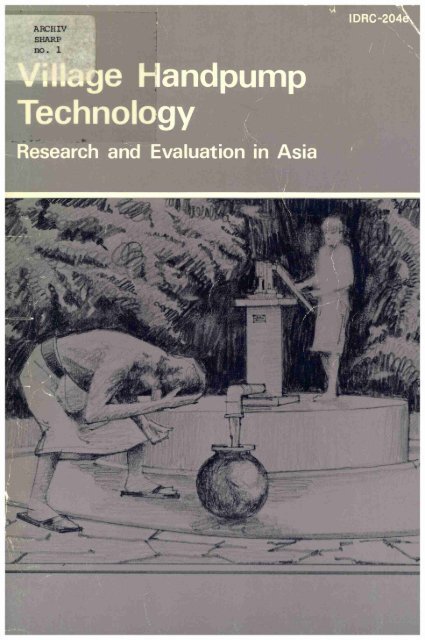
IDRC-204e<br />
Village Handpump Technology<br />
Research and Evaluation in Asia<br />
Editors: Village Handpump Technology Research and Evaluation in<br />
/
Résumé<br />
Depuis six ans le CRDI appuie financièrement des recherches sur la mise au point de<br />
pompes plus efficaces pour l'approvisionnement en eau potable des régions rurales. Les<br />
avantages de nouveaux matériaux et modèles de pompe ont été étudiés, plus particulièrement<br />
l'emploi de matières plastiques. L'Université de Waterloo a collaboré à la production d'un<br />
assemblage de cylindre et clapet de pied simple qui constituerait le premier élément d'une<br />
pompe à main pour puits de surface susceptible d'être fabriquée dans les pays en développement<br />
avec les ressources disponibles sur place. Soumise à des essais en laboratoire, la pompe<br />
a ensuite été testée dans diverses conditions environnementales dans quatre pays asiatiques<br />
et deux pays africains pour déterminer son coût de fabrication, sa fiabilité et sa durabilité, sa<br />
facilité d'entretien par les villageois et son efficacité technique. Cette publication passe en<br />
revue les résultats de recherche présentés à l'atelier tenu à l'Université de Malaya, Kuala<br />
Lumpur (Malaisie) du 16 au 19 août 1982, au terme des projets réalisés en Asie. Elle contient<br />
également une évaluation technique et économique globale des quatre projets et une évaluation<br />
des recherches à faire et des priorités à leur donner. Les futurs travaux porteront<br />
probablement sur la possibilité de lancer une production à grande échelle de pompes à main<br />
et sur les difficultés que présenterait la réalisation d'une telle entreprise.<br />
Resumen<br />
En los iltimos seis alios et CIID ha apoyado investigaciones tendientes a desarrollar<br />
sistemas màs efectivos de bombeo de agua para et àrea rural. Se han estudiado las<br />
implicaciones de los nuevos materiales y disenos de bombas, en especial et uso de materiales<br />
plâsticos. En colaboraciôn con la Universidad de Waterloo, se desarrollô un conjunto<br />
econômico de pistôn y vàlvula-pedal como base para una bomba manual de pozos pandos que<br />
pudiera ser fabricada en los paises en desarrollo con recursos locales. Después de ser ensayada<br />
en laboratorio, la bomba fue sometida a prueba bajo diferentes condiciones ambientales en<br />
cuatro paises de Asia y dos de Africa con et objeto de determinar costos de fabricaciôn,<br />
confiabilidad y durabilidad, capacidad de mantenimiento a nivel rural y desempeiio técnico.<br />
Este libro ofrece una resefia de los resultados de las investigaciones presentados durante un<br />
seminarici realizado en la Universidad de Malaya, Kuala Lumpur, Malasia, del 16 al 19 de<br />
agosto de 1982 a la culminaciôn de los proyectos asiàticos. Se incluyen ademés las<br />
evaluaciones técnicas y econômicas generales de los cuatro proyectos, asi como una<br />
estimaciôn de las futuras necesidades y prioridades de la investigaciôn, entre las cuales se<br />
contaràn probablemente et potencial de producciôn a gran escala y los problemas involucrados<br />
en la implantaciôn del sistema.<br />
2
Contents<br />
Preface ............................................................... 5<br />
Acknowledgments ..................................................... 6<br />
Introduction .......................................................... 7<br />
Sri Lanka<br />
Pathirana Dharmadasa, Upali Wickramasinghe, and<br />
Douglas Chandrasiri ................................................ 11<br />
Thailand Pichai Nimityongskul and Pisidhi Karasudhi ................ 21<br />
Philippines Antonio Bravo ......................................... 33<br />
Malaysia Goh Sing Yau ............................................ 39<br />
Overview of Technical Performance Goh Sing Yau .................. 53<br />
Economic Analysis and Potential Markets Tan Bock Thiam .......... 57<br />
Conclusions .......................................................... 67<br />
Participants ........................................................... 71<br />
3
Not ail the health assistants in the world can get rid of<br />
dysentery and choiera if water supplies are contaminated.<br />
Barbara Ward. 1976. The Home of Man.<br />
W. W. Norton & Company Inc., New York, NY,<br />
USA. Page 229.<br />
4
Preface<br />
Many factors are involved in efforts to provide safe drinking water for all during<br />
this the International Water Supply and Sanitation Decade. One of the keys,<br />
however, is the development and use of a reliable handpump that can be locally<br />
produced, installed, and maintained at a reasonable cost.<br />
The International Development Research Centre (IDRC) has invested about<br />
CA$ 730 000 in a network of water-supply projects in Asia and Africa over the last<br />
6 years to help develop more effective pump systems for rural water supplies. This<br />
publication reviews the results of the Asian segment of the network and identifies<br />
future research priorities, specifically the need to investigate large-scale manufacturing<br />
of the polyvinyl chloride (PVC) pump that has been developed and the<br />
essential social and public-health factors that must be part of any implementation<br />
program.<br />
It should be pointed out that the technology developed and tested by these<br />
IDRC-supported research projects is applicable to rural situations all over the<br />
world, not just to those few countries in Asia where field testing was carried out.<br />
The development of a handpump utilizing inexpensive PVC components, which<br />
can be manufactured locally and simply enough to be maintained at the village<br />
level, is a giant step forward in the struggle to provide adequate, clean, water<br />
supplies to rural populations.<br />
The technology has been tried, tested, and proven. But the question remains:<br />
how can the desire to utilize it and maintain it be best transferred to those who<br />
need it most? It is our hope that this volume will stimulate efforts to implement<br />
this technology and foster new research initiatives in all countries where provision<br />
of potable water is still a major problem.<br />
The papers presented in this publication are summaries of the full reports of<br />
each country project. More specific details may be obtained by writing to the<br />
Health Sciences Division of IDRC to obtain microfiche copies of the complete reports.<br />
Elizabeth Charlebois, Director<br />
Health Sciences Division<br />
International Development Research Centre<br />
5
Acknowledgments<br />
Over the past 6 years, many researchers, engineers, technicians, consultants,<br />
support staff, and others have contributed to the development of IDRC's concept<br />
of the village level operated and maintained (VLOM) handpump. The list is too<br />
numerous to acknowledge each person by name. It goes without saying, however,<br />
that it is the dedicated efforts of these people that made this publication possible.<br />
Thanks are also due to the University of Malaya, where the end-of-project<br />
seminar-workshop was held, and to Dr Goh Sing Yau, local coordinator, and his<br />
colleagues, Dr Tee Tiam Ting, Dr Tan Bock Thiam, Mr Chong Kah Lin, and Mr Teo<br />
Beng Hoe, for their hard work in ensuring the success of the meeting. Mr Lee Kam<br />
Wing acted as IDRC coordinator and a special word of thanks is due to Ai Ling Goh,<br />
Health Sciences Division, IDRC, Singapore.<br />
Also credit should be given to Tim Journey, who carried out the early design<br />
work for handpumps utilizing plastic components under the sponsorship of the<br />
World Bank and was later hired by IDRC to continue the effort.<br />
It must be pointed out that, although the pump described in this publication is<br />
often referred to as the IDRC-Waterloo design, it is really nothing more than an<br />
updated version of a wooden pump used in Europe about six centuries ago.<br />
Elements of the design are clearly illustrated in a 16th century plate appearing in a<br />
book on mining translated by Herbert Clark Hoover and Lou Henry Hoover in<br />
1950.<br />
It is interesting that scientists continually reinvent the wheel or, in this case, the<br />
pump.<br />
6
Introduction<br />
The precise links between improved water supply and health benefits are<br />
difficult to document. However, ail people appreciate the significance of a clean,<br />
adequate water supply. Nevertheless, an increased supply of safe water must be<br />
accompanied by certain behavioural changes that affect personal hygiene and<br />
sanitation practices before enteric diseases can be significantly reduced. These<br />
changes are complex and are not likely to occur spontaneously. The target population<br />
must be supplied with readily understood information about the benefits of<br />
change and convinced to adopt new behavioural patterns and accept new technologies.<br />
Furthermore, consumer acceptance of water and sanitation technology<br />
depends on devices that can hold up to abuse, function for long periods, and can<br />
be purchased and maintained by the villagers themselves.<br />
The selection, development, and use of reliable handpumps that can be locally<br />
produced and installed and maintained at a reasonable price is a major step toward<br />
providing reliable, safe drinking-water supplies to rural communities. Due to<br />
many technical and economic factors, such as the complexity of engine-driven<br />
pumps and the high cost of fuel, manual pumps will continue to be used in most<br />
parts of the world, not only for potable water but also for domestic use, livestock,<br />
and irrigation.<br />
For the past decade, senior officiais of national water authorities in developing<br />
countries, along with personnel from international and bilateral agencies, have<br />
observed that one of the most important problems in rural water-supply programs<br />
is the high failure rate of conventional manual pumps. Failures occur mainly<br />
because pumps were not designed for the level of stress and abuse encountered<br />
from large user groups within rural communities. Furthermore, the materials<br />
from which they are made, mainly cast iron and steel, are not only expensive, but<br />
also not readily available locally. Consequently, many developing countries have<br />
been relying on imported pumps and parts supplied by international and bilateral<br />
donors. This has implications in terras of costs, maintenance requirements, and<br />
problems of procurement of spare parts.<br />
For the past 6 years, the International Development Research Centre (IDRC)<br />
has been supporting research in the development of more effective pumping<br />
systems for rural water supplies. The approach taken has been to examine systematically<br />
the implications of new materials and improved pump designs. In view of<br />
the wide-spread introduction of plastics technology that has taken place in<br />
developing countries in the last decade, particular attention was focused on the<br />
polymer resins, specifically polyvinyl chloride (PVC) piping, which is widely available<br />
throughout Africa and Asia. In many respects, plastics technology is to<br />
developing countries what cast iron was to industrialized countries years ago and<br />
the vast potential of plastics has yet to be tapped.<br />
The IDRC-sponsored design work centred on developing a simple, low-cost<br />
piston and foot-valve assembly for a manual, shallow-well pump. This stage of the<br />
research, in collaboration with the University of Waterloo, was completed in<br />
May 1977. The piston and foot-valve assembly developed at the University of<br />
Waterloo was tested at the Consumer's Association Testing Facility in England.<br />
This testing program was initiated by the Overseas Development Ministry in the<br />
United Kingdom to analyze the characteristics of 10 commercially produced<br />
7
manual pumps that were manufactured in industrialized countries. The project<br />
established the reliability and efficiency of the Waterloo design compared with the<br />
existing technology. The Waterloo pump differs from others in that it has been<br />
designed specifically for fabrication in developing countries, utilizing existing<br />
locally available resources.<br />
In 1978, after the laboratory testing, research projects were set up in two<br />
countries in Africa and four in Asia to field test the pump under various environmental<br />
conditions and levels of technical sophistication with different user groups.<br />
The countries involved in this phase were Malaysia, the Philippines, Sri Lanka, and<br />
Thailand in Asia, and Ethiopia and Malawi in Africa.<br />
The Waterloo handpump has brought clean water to rural farnilies in Malaysia.<br />
8
The primary objectives of these studies were to assess the Waterloo pump design<br />
in various field conditions for characteristics such as capacity for local manufacture,<br />
cost of manufacture, reliability and durability, maintenance capability at the village<br />
level, and technical performance. The basic piston and foot-valve design produced<br />
by the University of Waterloo was used by all the projects with some local modifications.<br />
The above-ground components were locally designed and produced in<br />
each country.<br />
In the Philippines, the Institute for Small-Scale Industries at the University of<br />
the Philippines carried out the research in collaboration with the National Institute<br />
of Science and Technology, the Department of Local Government and Community<br />
Development, Department of Health, and the Local Utilities and Water Works<br />
Agency. In Thailand, the Asian Institute of Technology conducted the research<br />
in cooperation with the Department of Health, the Department of Public Works,<br />
the Office of Accelerated Development, and the National Economic and Social<br />
Development Board. In Malaysia, the Faculty of Engineering at the University of<br />
Malaya conducted the research in collaboration with the Environmental Engineering<br />
Division of the Ministry of Health. In Sri Lanka, the Lanka Jathika Sarvodaya<br />
Shramadana Sangamaya (the Sarvodaya Movement), which is involved in grassroots<br />
community-development work, carried out the research.<br />
The research included an economic analysis of cost effectiveness compared with<br />
other handpumps being used in the region. It also involved assessing the potential<br />
for rural water-supply development, making projections on the percentage of rural<br />
households that could be served by piped water, and attempting to determine the<br />
future market demand for handpumps in the region.<br />
In August 1980, the mid-project meeting for the four Asian projects was held at<br />
the University of Malaya in Kuala Lumpur to review the projects' progress and<br />
establish common monitoring and measurement techniques. A unique method for<br />
accurately determining pump usage with a mechanical counting device, developed<br />
at the University of Malaya, was also incorporated into the field-testing program.<br />
This device made it possible to correlate measurements of wear with the distance<br />
the piston traveled or the amount the pump was used.<br />
The activities of the four projects in Asia have now been completed and the<br />
results are encouraging. Two workshops were therefore sponsored by IDRC in<br />
collaboration with the Faculty of Engineering of the University of Malaya from<br />
16 to 19 August 1982 in Kuala Lumpur.<br />
For the first 2 days, the project leaders from the four Asian countries reviewed<br />
and discussed their results and assessed the overall technical and economic implications<br />
of their findings. During the last 2 days, a dissemination seminar was held to<br />
present the results to interested governmental and nongovernmental agencies<br />
from the region and to observers from various international agencies and private<br />
concerns. The status of handpump technology in the region was reviewed and new<br />
research priorities were identified.<br />
The PVC pump demonstrated during the field trials that it holds considerable<br />
potential for use at the village level. It can be made locally at reasonable cost and is<br />
easily repaired with locally fabricated parts. However, it must be realized that, as<br />
with any technology, there are limitations. If one is looking for a "magic,"<br />
maintenance-free pump, then this technology is not the answer. The results of<br />
field trials indicate that, although the pump is durable, there are limitations that<br />
must be understood and respected or malfunctions will occur. Also, failure will<br />
occur if the well is improperly developed. More importantly, the outcome of this<br />
research has clearly demonstrated that inexpensive plastics can be used in handpump<br />
manufacture, making it possible to produce pumps and spare parts locally<br />
and to incorporate designs that are simple to understand and easy to maintain at an<br />
affordable cost.<br />
This volume deal primarily with handpump technology, but it must be<br />
remembered that the pump is more than just a convenient means of drawing water<br />
9
from the well. It is an essential element in public-health efforts because the only<br />
sale way to provide adequate sanitary protection from surface contamination is to<br />
seal the well and install a pump. Unless this and other public-health measures are<br />
taken to protect the well, water-related diseases will continue to take their toll.<br />
In the coming years, limited resources will have serious consequences upon the<br />
provision of safe, adequate, water supplies for rural populations. If this problem is<br />
to be addressed, governments and water authorities must focus their resources on<br />
developing low-cost technologies that are easily understood, operated, and<br />
maintained at the village level. By publishing this volume, we hope that the results<br />
of this research will stimulate the implementation of such appropriate technology<br />
and at the same time foster new research initiatives.<br />
10
Sri Lanka<br />
Pathirana Dharmadasa,<br />
lJpali Wickramasinghe, and<br />
Douglas Chandrasiri<br />
The majority of the rural people in Sri Lanka<br />
obtain water for daily use from rivers, canals,<br />
lakes, irrigation tanks, and uncovered wells.<br />
The water from such sources is often unsuitable<br />
for drinking and most other domestic<br />
purposes. Because few people boil the water<br />
before drinking it, this results in many<br />
diseases: a fact that village people do not<br />
understand.<br />
The Sarvodaya Movement is playing a<br />
major role in setting up health-education<br />
programs and in providing facilities for<br />
improving the health of the rural masses in<br />
Sri Lanka. One composent of this program is<br />
the covered-wells program (Fig. 1). The main<br />
emphasis of this program is the introduction<br />
of low-cost handpumps made from locally<br />
available materials as a means of providing<br />
clean drinking water for household use.<br />
During this project, three new designs were<br />
developed for the above-ground components<br />
of the Waterloo pump developed with<br />
funding from the International Development<br />
Research Centre (IDRC). As well, several<br />
modifications were made to the piston and<br />
check valve, which was used in place of a foot<br />
valve, to make the pump easier to manufacture<br />
with local resources. The goal of this<br />
design work was to develop a pump that<br />
incorporated the following features: the use<br />
of low-cost materials available in Sri Lanka;<br />
easy maintenance and repair without the<br />
need for highly skilled labour; and the use of<br />
polyvinyl chloride (PVC) plastic to eliminate<br />
corrosion problems.<br />
Organization of the Project<br />
A preliminary survey was undertaken in<br />
January 1979 in several villages in the districts<br />
of Galle, Matara, and Hambantota to investigate:<br />
the economic situation in the villages;<br />
the existing social conditions; the irrigation<br />
facilities; and the attitudes of the villagers<br />
toward handpumps. Based on the findings of<br />
this survey, it was initially decided to install<br />
60 pumps in six villages, but later, due to<br />
Fig: 1. View of well showing drainage channel to remove spilled water and stone layer to assist drainage.<br />
11
geographical and political reasons, the number<br />
was reduced to four pumps in each of five<br />
villages: Akurala Village, Talawa Village,<br />
Hingurudugoda Village, and Ginimellagaha<br />
Village in the Galle District and Yatiyana<br />
Village in the Matara District. In addition,<br />
one pump was installed at the Sarvodaya<br />
Centre office for demonstration purposes.<br />
The project was divided into three phases:<br />
construction of the wells, installation of the<br />
pumps, and inspection and field testing.<br />
During the study, the importance of covering<br />
the wells and the health problems caused by<br />
using water from uncovered wells was<br />
emphasized to the villagers. All construction<br />
work was carried out by the Sarvodaya Rural<br />
Technical Service. The pumps were assembled<br />
and installed by the Engineering Section of<br />
the Sarvodaya Movement, and the survey<br />
work was handed over to a team selected for<br />
the purpose.<br />
The preliminary surveying was completed<br />
by July 1979 and the construction work completed<br />
by February 1980. During February-<br />
August 1980, the pumps were installed and<br />
the monitoring work was started. Pump<br />
pistons, piston rings, fulcrum shafts, journals,<br />
check valves, check-valve bolts, and pump<br />
heads were produced at the Sarvodaya Main<br />
Centre. Parts that were easier to make were<br />
produced at the Village Centres.<br />
Location and Construction of Wells<br />
Careful consideration was given to the<br />
placement of wells. The wells were located at<br />
least 30 m from the nearest latrine or other<br />
source of contamination and in well drained<br />
areas devoid of surface water even during<br />
heavy rains (1 m = 3.28 ft). The wells were<br />
constructed by digging a pit and positioning a<br />
precast concrete ring in the hole. A second<br />
ring was then added and digging continued<br />
until the water table was reached. These<br />
concrete rings, therefore, formed the walls of<br />
the well. This technique was so successful<br />
that the Sarvodaya Rural Technical Service<br />
committee decided to construct all the wells<br />
in the same way. Moulds for the rings were<br />
Table 1. Summary of material used, fabrication equipment required, cost, and quality of the components<br />
used in different pump designs.<br />
Pump element Material Tools and equipment<br />
Cost (Rs)b<br />
and design used' required Material Labour Quality<br />
Frame<br />
Li Angle iron Welder, hacksaw 145 90 Satisfactory<br />
L2` Concrete Mason's tools, mould 80 60 Poor<br />
L3 Angle iron, Drill, hacksaw, welder, 210 150 Very good<br />
Vl<br />
CI sheet metal sheet-rnetal tools<br />
CI pipe, Hacksaw, welder, drill 30 50 Good<br />
MS plate<br />
Handle<br />
Li<br />
CI pipe, MS, Drill, hacksaw, lathe, 80 100 Good<br />
L2<br />
brass bushings<br />
Wood<br />
welder<br />
Carpenter's tools 120 80 Poor<br />
L3 CI pipe Hacksaw, welder, 100 100 Very good<br />
Vl<br />
blacksmith's tools<br />
Wood, bolts, Carpenter's tools, hacksaw, 12 60 Satisfactory<br />
washers drill, files<br />
Piston and check valve<br />
lst Wood, leather Lathe, drill, leather cutter 10 50 Not durable, low<br />
2nd PVC Lathe, drill, solvent cernent, 175 90<br />
volumetric efficiency<br />
Leaked, broke easily<br />
3rd<br />
PVC, Wood<br />
blowtorch<br />
Lathe, drill, solvent cernent 100 50 Good<br />
'Abbreviations: GI, galvanized iron; MS, mild steel; PVC, polyvinyl chloride.<br />
°Rs20 - US$1<br />
`Because of problems with this design, it was eliminated from the field testing. Wells originally having these pumps were<br />
fitted with L3 pumps instead.<br />
12
m O C O x<br />
00<br />
N<br />
.,y D+ O<br />
G+ CL C n Qp m rt<br />
m<br />
a p' O C<br />
w<br />
m<br />
mm<br />
Me «I<br />
-M<br />
-<br />
l- r r INI<br />
8
Description of Pumps<br />
The three pumps that were designed during<br />
this project shared essentially the same belowground<br />
components but differed significantly<br />
in their above-ground configuration. The<br />
modifications made to both the belowground<br />
and above-ground parts are described<br />
in detail below and summarized in Table 1.<br />
Below-ground components<br />
A PVC check valve based on the original<br />
Waterloo design was used in the Vi-type<br />
pump; in the other pumps, however, the<br />
piston and check valve were changed to those<br />
shown in Fig. 2. In the modified pistons and<br />
check valves, a piece of wood with eight holes<br />
drilled in it is inserted in a section of PVC<br />
pipe 5 cm long with an outside diameter of<br />
4.5 cm (1 cm = 0.39 in.). In this new design,<br />
the piston seal is obtained by using locally<br />
made leather cups. These were used instead<br />
of rings made of polyethylene, a material that<br />
is not manufactured in Sri Lanka, is difficult<br />
to obtain, and is expensive. Leather, however,<br />
is available ail over the island. The PVC<br />
washers were made locally by flattening<br />
heated PVC pipe and then forming the<br />
washers on a lathe. The plate valve is made<br />
from flattened PVC pipe on which a piece of<br />
leather is glued to create a seal and prevent<br />
leaking. This change was required because<br />
severe leakage was observed when PVC and<br />
A<br />
Fig. 3. (A) Threaded PVC piston rod couplings and (B) PVC<br />
piston rod guides glued to piston rod to reduce vibration during<br />
operation of pump: (1) connecting rad; (2) threaded coupling;<br />
(3) riser pipe; and (4) rad guides.<br />
B<br />
brass were used together. The use of a<br />
leather valve completely solved this problem.<br />
A piece of galvanized steel wire, used to<br />
make the spring, was held in place by a brass<br />
nut and washer. A threaded brass "Y' boit<br />
12.5 cm long holds the parts of the piston<br />
together. A 3.5-cm long brass bushing is<br />
placed over the "F' boit to facilitate movement<br />
of the plate valve. This bushing also ensures<br />
the proper spacing of the components of the<br />
piston and check valve and correct tension of<br />
the spring when the parts are assembled.<br />
The connecting-rod guides in the pump<br />
cylinder are made of PVC pipe cut into sections<br />
and solvent-welded to the PVC rod.<br />
Threaded couplings are used to join the<br />
sections of the piston rod together (see Fig. 3).<br />
Initially, the rods were joined using a boit, but<br />
the bolts broke because of stress at the joint.<br />
The use of PVC couplings has been very<br />
successful.<br />
Above-ground components<br />
The L3 pump<br />
For field-testing, a total of six of these pumps<br />
were installed. Four at Talawa and one each<br />
at Ginimallagaha and at the Sarvodaya Main<br />
Centre. These pumps were used to replace<br />
the L2 pumps that had been installed originally<br />
in these wells. The frame of the L2 was made<br />
out of concrete and used a wooden handle.<br />
The original L3 pumps also used a handle that<br />
pivoted on a bearing fixed in a concrete<br />
pedestal. Although this arrangement proved<br />
more successful than the L2 pump, it also had<br />
to be changed because of excessive, and rapid,<br />
wear of the wood at the pivot point. This<br />
meant that the handle could be lowered to the<br />
point where it would make contact with the<br />
outlet spout, resulting in a constant banging<br />
by the handle during the operation of the<br />
pump that resulted in the joint between the<br />
pump head and the spout cracking. This<br />
problem was remedied by designing a new<br />
handle that prevented overlowering and at<br />
the same time made the pump easier to<br />
operate (Fig. 4).<br />
Frame Angle iron is used to make the<br />
square frame for this pump. Four 9-mm bolts<br />
are welded to the upper section of the frame<br />
to hold the pump head and four 12.5-mm<br />
holes are drilled in the lower section for<br />
attachment to the well (1 mm = 0.039 in.).<br />
Two brackets made of flat iron are used to<br />
14
13<br />
8<br />
-6<br />
7<br />
9<br />
10<br />
A B C<br />
Fig. 4. (A) LI pump, (B) L3 pump, and (C) VI pump: (1) handle; (2) (rame; (3) spout; (4) piston rod; (5) riser pipe; (6) piston<br />
rod guide; (7) piston rod joint; (8) riser pipe joint; (9) piston; (10) check valve; (I I) wooden bearing and counter box (L7 and V I );<br />
(12) main bearing (L3); (13) big-end bearing (L3); and (14) counter base (L3).<br />
hold the riser pipe. One is welded to the lower<br />
section of the (rame, the other is fixed to the<br />
stationary bracket with 6-mm bolts (see Fig.<br />
5).<br />
Bearings Wood (satin or palu) is used for<br />
both sets of bearings. One set is fitted to the<br />
piston rod. The other set is used for the pivot<br />
point in the handle and is designed so that<br />
the bearing can be reversed once wear is<br />
excessive, thus prolonging the life of the<br />
bearing (Fig. 5).<br />
Spout The spout is made of 25-mm<br />
galvanized pipe. The pipe is filled with sand<br />
to prevent crimping and bent using heat on a<br />
specially designed jig made by the project<br />
staff. The other end is threaded to fix it to<br />
the pump head.<br />
Connecting rod A 19-mm PVC pipe is used<br />
for the piston rod. The sections of the rod<br />
are joined using threaded PVC couplings<br />
and the rod is connected to the piston using<br />
a threaded brass coupling.<br />
A galvanized sheet-metal<br />
Frame caver<br />
(22 gauge) cover is attached to the frame with<br />
nuts and bolts. The upper section, which can<br />
be removed, is tapered to protect the pumping<br />
mechanism from rain, which is important for<br />
prolonging the life of the wooden bearings.<br />
The removable cover also allows easy access<br />
for inspection and maintenance.<br />
Handle Originally, the handle was<br />
mounted on one side of the pump frame.<br />
However, this design caused excessive wear<br />
on the wooden bearing and thus the design<br />
was changed. The handle is now made of<br />
12.5-mm galvanized pipe and two pieces of<br />
flat iron (see Fig. 5). This handle was designed<br />
to increase the life of the wooden bearing,<br />
make the pump easier to use, and at the same<br />
time limit the length of the stroke. When<br />
the handle is lowered too far, the user's hand<br />
bangs on the iron spout. This simple design<br />
feature not only protects the internai parts of<br />
the pump from damage but also allows the<br />
pump to be locked with a chain and padlock<br />
if desired.<br />
The LI pump<br />
Six of the Li pumps were installed in<br />
Baddegama, three at Ginimallagaha, and<br />
three at Hingurudugoda. The above-ground<br />
15
inch<br />
0t-r1<br />
10<br />
10<br />
30<br />
cm<br />
20<br />
50<br />
B<br />
CD<br />
1<br />
C (top)<br />
A<br />
Fig. 5. Details of L3 pump: (A) (rame and wooden bearings, (B) big-end bearing, and (C) final handle design showing position of<br />
wooden bearings.<br />
components of these pumps (see Table 1 and<br />
Fig. 4) worked well and did not require<br />
modification. Originally, a 7.5-cm cylinder<br />
was used for the riser pipe and a 5-cm pipe<br />
was used for the above-ground portion of the<br />
pipe. However, this meant that the 7.5-cm<br />
piston could not be removed for repairs without<br />
cutting the cylinder. To make repairs<br />
easier and to save time and labour, a 5-cm<br />
piston is now used along with a 5-cm pipe<br />
for the entire length of the riser pipe and<br />
cylinder.<br />
The V i pump<br />
Nine of the Vl pumps (Fig. 4) have been<br />
installed: four at Akurala; four at Yatiyana;<br />
and one at Hingurudugoda. The wells at these<br />
sites are 3-4 m deep. The above-ground<br />
components of this pump were modified based<br />
on our experience, the results of the field<br />
testing, and the suggestions of the users. We<br />
found that the original metal handle made<br />
this pump difficult to operate, therefore we<br />
switched to a wooden handle. We also discovered<br />
that the piston could be pulled out of<br />
the cylinder during use so we installed a<br />
simple metal bracket to prevent over-raising<br />
(see Fig. 6). The cost of this pump is low;<br />
about US$75 for the complete pump to draw<br />
water from 3 m. However, because there is<br />
no lever mechanism in the design, the user<br />
must lift the full weight of the water in the<br />
column, thus making extensive use tiring.<br />
Frame The pump frame is made of 5.1-cm<br />
galvanized pipe. A galvanized plate is used to<br />
fix the frame to the well and a 2.5-cm socket<br />
is welded onto the frame for attachment of<br />
the spout.<br />
Spout The spout, made of 2.5-cm pipe,<br />
is screwed to the pump frame. The other end<br />
of the spout is bent, using heat, to an angle<br />
of 90°.<br />
Handle Hard wood such as satin and jak<br />
is used to make the handle, which is held in<br />
place by a bolt. The pump is very easy to<br />
operate, but usage for a long period can be<br />
tiring. In a few instances, the wooden handle<br />
broke when the pump was in operation; however,<br />
it is interesting to note that the people<br />
16
in the village can easily make a new handle<br />
themselves.<br />
Main pipe PVC pipe, 5 cm in diameter, is<br />
used for the riser pipe. Although the outside<br />
of the pipe is smooth, the inside is rough and<br />
not completely round because of local manufacturing<br />
problems. Because of these problems,<br />
it was impossible to obtain an adequate seal in<br />
the piston and check valve using PVC rings.<br />
Instead, leather cups that could be made in<br />
the villages were designed to solve this<br />
problem. These cups were made using a<br />
simple press and a locally fabricated die. The<br />
leather was treated with tallow and held in<br />
the press for about 30 minutes to acquire the<br />
required shape. These cups have been used<br />
for more than 1 year and continue to give<br />
good results. Problems were also encountered<br />
when the locally available couplings were used<br />
to join the 5-cm riser pipe. These couplings<br />
produced poor quality joints and, because of<br />
their configuration, left a ridge in the joined<br />
pipes. This ridge created a problem because<br />
the leather piston cups stuck at the joints<br />
making it impossible to remove the piston<br />
except by cutting the riser pipe. To overcome<br />
this problem, the pipes were joined by making<br />
bell joints. The end of the PVC pipe was<br />
dipped in hot coconut oil to soften the plastic<br />
and then it was forced over a locally made<br />
metal form to increase its diameter enough<br />
to fit tightly over the normal end of the<br />
adjoining pipe. The pipes could then be joined<br />
with solvent cernent. This system has worked<br />
well and allows the piston to be removed easily<br />
for maintenance and repair.<br />
A<br />
B<br />
01<br />
O<br />
M<br />
E<br />
M<br />
c<br />
M<br />
TJ<br />
inch<br />
cm<br />
12<br />
ô<br />
Technical Assessment<br />
During the course of the field testing, a<br />
number of design modifications using locally<br />
available materials and expertise were introduced<br />
to solve problems. Extensive measurements<br />
were also made of the wear of the<br />
piston rings, piston plate valve, check valve,<br />
journals, fulcrum shaft, and connecting rod to<br />
assess the durability of these pumps under<br />
field conditions. The technical performance of<br />
the pumps was also measured with the aid of<br />
a specially mounted counter (see Fig. 6). This<br />
C<br />
counter measured the length of each stroke<br />
of the piston and thus gave a reading on the<br />
Fig. 6. (A) Stop and counter box attached to VI pumps, (B) amount of use of the pump. The volumetric<br />
details of counter installation, and (C) counter assemhly from efficiency of the pump was calculated from:<br />
VI pump. volumetric efficiency = (actual discharge x 100)1<br />
17
(cylinder area x length of standard stroke).<br />
The mechanical efficiency of the pumps was<br />
also calculated.<br />
During the initial stages of the testing,<br />
many pumps malfunctioned because the joints<br />
in the piston rod broke. The galvanized bolts<br />
used to join the sections broke after about<br />
3 months of use due to vibration of the piston<br />
rod during operation of the pump. In addition,<br />
the holes drilled in the piston rod at the joints<br />
caused weakness and, occasionally, breakage<br />
of the rod. The rods are now joined with<br />
threaded PVC couplings that are readily<br />
available locally. The couplings are glued to<br />
the ends of the rods and the rods are screwed<br />
together. This method has been very satisfactory.<br />
As well, guides made of sections of<br />
PVC pipe were attached to the piston rod (see<br />
Fig. 3). These guides reduced the amount of<br />
vibration of the piston rod and thus reduced<br />
some of the fatigue problems.<br />
In the Li pump, a 7.5-cm diameter pipe<br />
was used as the pumping cylinder to increase<br />
the output of the pump; however, this caused<br />
problems because the piston could not be<br />
raised above the cylinder section as the riser<br />
pipe was of smaller diameter. To remove the<br />
piston for repair or maintenance, the cylinder<br />
had to be cut. Therefore, in all pumps, we<br />
now use 5-cm pipe throughout the entire<br />
length of the riser pipe and cylinder. One<br />
problem still remains with the riser pipe: the<br />
joints in the pipe occasionally separate during<br />
pumping because of the vibration of the pipe.<br />
However, this problem was only observed<br />
when the riser pipe is more than 5 m long. For<br />
shallower wells, this has not been a problem.<br />
Because the riser pipe was open at the end,<br />
the original check valve with polyethylene<br />
rings frequently dropped into the well: again<br />
because of vibration during operation of the<br />
pump. The use of leather cups in the valve<br />
seems to have solved this problem. For additional<br />
security, the end of riser pipe is heated<br />
and crimped to prevent the check valve from<br />
falling into the well. A screen placed over the<br />
end of the riser pipe was also used to correct<br />
this problem but crimping the end of the<br />
pipe was found to be more practical.<br />
Local fabrication of the Waterloo piston<br />
and check valve cause considerable difficulty<br />
because solid PVC stock is not available in Sri<br />
Lanka. Several attempts were made to improvise<br />
with locally available materials. Initially,<br />
we tried making a "solid" rod or cylinder by<br />
gluing progressively smaller PVC pipes inside<br />
one another. Problems were encountered<br />
with this design because, when grooves were<br />
cut for the piston rings, the ends of the rod<br />
tended to break off. It was also very difficult<br />
to drill holes along the length of this "built-up"<br />
pipe. Next, we tried to fabricate the piston<br />
and check valve from wood and still use<br />
polyethylene rings as a seal. Although the<br />
construction of the valves was easier, they<br />
were not successful because the piston rings<br />
stuck in the grooves and did not seal properly<br />
against the wall of the riser pipe. Also, a poor<br />
seal resulted because of the rough inside surface<br />
of the PVC pipes available in Sri Lanka.<br />
This rough surface also quickly wore the<br />
polyethylene rings, resulting in burrs on<br />
the edge of the rings, which contributed to<br />
their sticking in the grooves.<br />
The problems related to these valves were<br />
eventually solved by using a design that<br />
combined a hollow PVC pipe with a wooden<br />
core and employed leather cup seals. This<br />
design (see Fig. 2) completely solved the<br />
leakage problem. Not only was the problem of<br />
leakage remedied but the wear of the riser<br />
pipe was also lessened. When polyethylene<br />
rings were used during field testing, the riser<br />
pipe wore by 0.35 mm after 90 days of use.<br />
This is believed to be due to silt particles<br />
becoming embedded in the rings and acting<br />
like sandpaper against the cylinder wall.<br />
Similar tests with leather cups produced<br />
much less wear. This design makes local<br />
fabrication and repair possible and it has<br />
proven its reliability under field conditions<br />
for over 1 year.<br />
During the field testing of these pumps,<br />
two types of check valves were tried. In the<br />
Vi pumps, a check valve using a rubber plate<br />
valve was screwed into the bottom of the<br />
riser pipe. However, a retrievable check valve<br />
of the same design as the PVC-wood piston<br />
was used for the Li and L3 pumps. A rubber<br />
plate valve was used in the Vl pump and it<br />
worked very well (Fig. 7). But, because it is<br />
screwed to the riser pipe, its use is only<br />
practical in shallow wells where it is easy to<br />
remove the entire length of riser pipe to<br />
service the valve. The PVC-wood valve<br />
(Fig. 2) used in the Li and L3 pumps can be<br />
extracted without removing the riser pipe.<br />
Because it incorporates leather cups and a<br />
PVC-leather plate valve, the villagers can<br />
easily repair worn parts themselves. Rubber<br />
suitable for the plate valve used in the Vi<br />
pump, on the other hand, is not so easily<br />
18
Table 2. Overview of performance data,' measurements of wear, and maintenance and repair required.<br />
Percentage<br />
Volumetric Water Avg water<br />
wear<br />
Down<br />
Pum type Number of efficiency head output Piston time<br />
a,n enance an repars<br />
M t d<br />
p<br />
and number users (%) (m) (Llday) rings Cylinder Journals (days) Parts (US$) Time (hours)<br />
V 1 pumps<br />
BA 01 73 80 3.4 900 12 7.5 11 7 17.70 3.25<br />
BA 02 50 65 1.5 403 22 9 12 6 11.75 3.50<br />
BA 03 48 91 1.4 115 15 10 22 4 11.25 2.00<br />
BA 04 56 74 1.4 285 12.5 5 21 5 11.10 2.00<br />
BH 15 44 62 2.9 821 13 8 21 3 3.50 2.00<br />
MY 17 17 85 2.4 292 3.8 2.5 20 3 5.00 2.00<br />
MY 18 21 69 2.9 726 11 5 23 - - -<br />
MY 19 43 73 1.8 289 13 5 22 4 4.75 1.50<br />
MY 20 34 55 1.2 49 16 2.8 11 3 1.25 0.25<br />
L3 pumps<br />
BT 05 21 77 3.0 513 14.1 7 8 6 14.00 4.50<br />
BT 06 27 84 2.3 400 15 5.2 7 6 18.75 6.00<br />
BT 07 62 75 5.4 536 14.6 8 8.8 6 10.00 4.75<br />
BT 08 29 69 6.0 476 12 5.8 12 6 8.50 5.75<br />
BG 12 32 86 7.9 340 11.5 7.9 9 7 12.00 6.25<br />
MC 21 50 80 5.9 100 - - - 1 - 1.00<br />
LI pumps<br />
BG 09 46 99 3.5 490 7 9.2 1.3 11 19.00 6.50<br />
BG 10 52 87 5.3 875 5.5 3 1 10 20.00 7.00<br />
BG 11 58 89 6.6 832 13 5 2 11 15.00 4.50<br />
BG 13 42 88 2.8 930 12 5.7 1.6 6 14.50 3.50<br />
BG 14 33 92 2.5 705 6 5.5 1.4 8 15.85 5.25<br />
BH 16 76 93 3.3 972 4.8 10.5 2 7 2.50 3.50<br />
'1 m = 3.28 feet; 1 L = 0.22 gallon.
Fig. 7. Details of check valve used in VI pumps: (1) PVC cover; (2) rubber ring; (3) brass nui and washer; (4) rubber check<br />
valve; (5) PVC plate; (6) PVC screen; (7) brass boit; and (8) brass spring.<br />
obtained and is more expensive.<br />
Using the mechanical counting device, it<br />
was possible to determine the amount of<br />
usage of each pump. Estimates were then<br />
made on the average water output in litres<br />
per day, the distance the piston had traveled,<br />
and the amount of wear each composent had<br />
undergone in relationship to usage. Table 2<br />
provides a summary of performance data<br />
collected from March 1981 to April 1982.<br />
The results of this monitoring indicated that<br />
the L1 pump experienced the least amount of<br />
wear and maintained the highest volumetric<br />
efficiency. This was probably due to the<br />
leather cup seals. Because it was sot possible<br />
to purchase high quality PVC piping, i.e.,<br />
most pipes were out-of-round and were rough<br />
on the interior surfaces, the initial wear on<br />
the polyethylene rings was substantial until<br />
abrasion shaped the rings to the interior<br />
configurations of the cylinder. Wear on the<br />
journals (bearings) varied greatly according<br />
to the material used. For example, the brass<br />
bearings used in the L1 pump wore a maximum<br />
of 2%, whereas wear on the wooden<br />
bearings used in the L3 pump was as much<br />
as 23%. It was found that, although wooden<br />
bearings are more subject to wear, this wear<br />
does sot hinder the operation of the pump; in<br />
contrast, as little as 1 mm of wear on brass<br />
bearings makes the pump difficult to operate.<br />
It was interesting to note that, of the three<br />
pumps tested, type L1 was subjected to the<br />
largest user groups, the average being 51 persons.<br />
Type L3 experienced the least amount<br />
of usage with an average of only 37 persons<br />
per group. An average of 42 persons per<br />
group used pump VI. Even with the larger<br />
numbers of people using the L1 pump, the<br />
breakdown rate was not any higher than the<br />
L3 model. The Vi model, or direct action<br />
pump, had the lowest breakdown rate.<br />
To conclude, although the original concept<br />
of the Waterloo design was to utilize polyethylene<br />
rings to create a seal between the<br />
piston and cylinder and the foot valve and<br />
cylinder, this was not successful due to the<br />
poor quality of the PVC piping and the fact<br />
that polyethylene is not easy to obtain.<br />
Because leather is easily accessible and<br />
inexpensive, this was the logical alternative.<br />
Using a metal die, it was fairly easy to shape<br />
the leather into the desired form. This<br />
technique is simple enough to be mastered by<br />
a village worker. Although the L1 angle-iron<br />
pumps were durable, wear on the brass bearings<br />
made their operation difficult. It was,<br />
therefore, more practical and less expensive<br />
to use the wooden bearings, as in the L3<br />
model, even though they required more frequent<br />
maintenance.<br />
We feel that the pump that has been<br />
developed as a result of this IDRC-supported<br />
project is durable, can be produced at a<br />
reasonable cost, and can be maintained at the<br />
village level with very little special training.<br />
The Waterloo pump research<br />
Acknowledgments<br />
program was carried out by the Lanka Jathika<br />
Sarvodaya Shramadana Movement (Inc.) Sri Lanka<br />
and sponsored by IDRC. We wish to express our<br />
sincere thanks to: the Sarvodaya Coordinators in<br />
the Galle District, Mr Danny Dissanayaka, and the<br />
Matara District, Mr P. Hewavitharana; Mr Karl<br />
Wherle, Mr Thomas Zimmerman, and Mr Gunapala<br />
Ganegama of the Rural Technical Section Unit,<br />
Sarvodaya, Moratuwa; and to all the workers in the<br />
Sarvodaya Gramodaya Centres and the people who<br />
helped us to make this task a success.<br />
20
Thailand<br />
Pichai Nimityongskul and Pisidhi<br />
Karasudhi<br />
The National Economic and Social Development<br />
Board of Thailand reports that more<br />
than 80% of the people in Thailand live in<br />
rural villages and that only 40% of these<br />
people have access to a safe water supply.<br />
Although people in the urban areas have<br />
a relatively good quality water supply, the<br />
supply in rural communities is far from<br />
adequate. In rural areas, potable water and<br />
water for other domestic purposes is obtained<br />
from various sources: rainwater catchment,<br />
deep or shallow wells, reservoirs, ponds, and<br />
streams. Of these sources, water from deep<br />
or shallow wells is the safest in terms of<br />
protection from waterborne diseases.<br />
Approximately 90% of the existing wells in<br />
Thailand use handpumps and over 5 million<br />
people depend on these handpumps to obtain<br />
their water for consumption and other<br />
domestic uses. As a result, handpumps are<br />
an integrated part of the life of the rural<br />
people and the operation and maintenance of<br />
these pumps poses a challenging task. It is<br />
estimated that the cost of repair and maintenance<br />
of the 7000 handpumps installed by<br />
the Department of Minerai Resources alone<br />
is over US$500 000 annually. Furthermore,<br />
NIDA (1978) reported that, based on a<br />
random sample, roughly 5000 of the 19 000<br />
handpumps installed in Thailand by different<br />
government agencies were out of operation<br />
on any given day.<br />
Purpose and Scope of the Project<br />
The main objective of this study was to test,<br />
under various field conditions, the handpump<br />
developed at the University of Waterloo and<br />
subsequently to modify and optimize the<br />
handpump design to suit local conditions.<br />
Specifically, the aim of this study was to:<br />
(1) conduct a review of the handpumps<br />
currently used by the five main government<br />
agencies responsible for rural water supply<br />
in Thailand; (2) carry out laboratory tests on<br />
various handpump types, including the<br />
Waterloo pump, to compare their performance<br />
and endurance under various conditions;<br />
(3) install and conduct field tests of the<br />
Waterloo handpump configuration; and<br />
(4) based on the field and laboratory test<br />
results, adapt and improve the Waterloo<br />
design and field test the modified handpump<br />
under village conditions.<br />
This project was sponsored by the International<br />
Development Research Centre<br />
(IDRC) and carried out with the cooperation<br />
of the following Thai government agencies:<br />
Department of Minerai Resources (DMR),<br />
Ministry of Industry; Department of Health,<br />
Ministry of Public Health; Department of<br />
Public Works, Ministry of Interior; Office of<br />
Accelerated Rural Development (ARD),<br />
Ministry of Interior; and Agricultural<br />
Technology Office, Ministry of Agriculture<br />
and Cooperatives. In addition, the National<br />
Economic and Social Development Board of<br />
the Office of the Prime Minister served as<br />
the coordinator for these agencies.<br />
Review of Existing Handpumps in<br />
Thailand<br />
Historically, the existing handpumps in<br />
Thailand originated from Europe and North<br />
America and were designed for use by a<br />
single family in the developed countries. In<br />
developing countries, the pump was shared<br />
by many people living in the rural community<br />
and, because of the increased usage, it broke<br />
quite often and, in most cases, could not be<br />
repaired by the villagers. According to the<br />
ARD Office (1980), several different types of<br />
handpumps have been installed in Thailand<br />
by different government agencies. However,<br />
the different handpumps in Thailand can<br />
be broadly classified into two groups: the<br />
DMR handpumps and the ARD handpumps.<br />
The prototypes of the handpumps from<br />
the DMR are the Demster, Red Jacket, and<br />
other handpumps donated by, or procured<br />
from, the United States of America. This<br />
type of handpump has a three-pin lever with a<br />
cross head and a cylinder that generally has<br />
a plunger with two leather cup seals and a<br />
poppet valve at the plunger. The lower valve<br />
21
consists of a spring-activated poppet and the<br />
pump has a 3-inch (7.5-cm) cylinder, 7/16-inch<br />
(11-mm) pumping rod, and 1.25-inch (3-cm)<br />
drop pipe (riser pipe). The inlet-valve lining,<br />
piston cup, top gasket, and cylinder gasket of<br />
these pumps are made of leather, whereas the<br />
spout gasket is made of rubber. There are<br />
42 different components and most of them<br />
are made of brass. Cold-drawn steel is used<br />
for the cylinder reducing coupling, bottom<br />
fulcrum pin, and piston rod.<br />
The handpumps provided by the Public<br />
Work Department are also included in this<br />
group because they are similar to DMR handpumps<br />
except that the drop pipe is slightly<br />
larger (1.5-inch, 3.8-cm diameter).<br />
The ARD handpump, which is usually<br />
called the Korat handpump, has been adopted<br />
by the Department of Health, the ARD Office,<br />
and the Local Administration Department.<br />
The pump mechanism consists of a rack and<br />
pinion (gear type). Leather is used for the<br />
piston seal, gasket, and bushing seal. All of<br />
the packing nut caps, valves, locks, and handle<br />
gear bushing are made of brass. The pump<br />
has a 3-inch (7.5-cm) cylinder and 1.25-inch<br />
(3-cm) drop pipe and is composed of 32<br />
components.<br />
There is a slight difference in the handpump<br />
supplied by ARD. It is essentially the same as<br />
the Korat handpump except that it has a<br />
3-inch (7.5-cm) cylinder made of polyvinyl<br />
chloride (PVC) and 1.25-inch (3-cm) drop<br />
pipe. The pumps supplied by the Local<br />
Administration Department are normally<br />
used for shallow wells.<br />
The advantages and disadvantages of the<br />
DMR and ARD handpumps are summarized<br />
in Table 1.<br />
In the Waterloo handpump, basically, all<br />
the components are made of rigid PVC and<br />
polyethylene, which are low cost commodity<br />
polymers. These plastics have been selected<br />
for ease of manufacture and low cost as well<br />
as for their efficiency. The below-ground<br />
components consist of a PVC well casing that<br />
also functions as the pump cylinder for the<br />
plastic piston. The plastic foot valve is<br />
constructed of components that are common<br />
to the piston (Fig. 1). The flow of water in the<br />
piston and foot valve is regulated by simple<br />
rubber plate valves. Polyethylene piston rings<br />
provide adequate hydraulic seals on the piston<br />
with much less frictional resistance than<br />
leather cups or rings. It has been found that<br />
wear is concentrated on the rings, which can<br />
be replaced easily, rather than on the well<br />
casing. The foot valve can be removed easily<br />
for inspection or repair and serves as a reserve<br />
piston whenever necessary. Both 2-inch<br />
(5-cm) and 3-inch (7.5-cm) diameter pistons<br />
were used in this study.<br />
The pistons and foot valves for the<br />
Waterloo pumps were made at the Asian<br />
Institute of Technology (AIT) using locally<br />
available PVC rods. The piston rings and<br />
foot-valve adapters were made from polyethylene<br />
supplied by IDRC. Based on the<br />
results of the laboratory and field tests, the<br />
piston and foot valve were later modified.<br />
Table 1. Advantages and disadvantages of existing handpumps in Thailand.<br />
DMR<br />
Advantages<br />
The air chamber of the above-ground component<br />
helps maintain a continuous flow of water<br />
The handle is made of a single piece of cast iron<br />
having appropriate shape and size, hence it is<br />
easy to operate and is durable<br />
Disadvantages<br />
Direct contact between the axle and the bushing<br />
causes rapid wear<br />
If the axle breaks, the handle can moue horizontally<br />
and may damage other parts<br />
The contact area between the axle and stuffing box<br />
is relatively loose. This can result in eccentric<br />
movement of the pumping rod and reduced pump<br />
efficiency<br />
The plunger could slam against the upper and lower<br />
parts of the cylinder if not properly installed<br />
The cast-iron fulcrum link is not strong enough<br />
and, under repeated use, tends to break<br />
ARD<br />
Advantages<br />
Vertical movement of the pumping rod is by using<br />
a rack and pinion<br />
There are fewer moving parts subject to wear and<br />
tear<br />
The shock-absorbing spring prevents the plunger<br />
from slamming against the upper and lower<br />
parts of the cylinder<br />
Disadvantages<br />
The flow of water is not continuous due to the<br />
absence of an air chamber<br />
The handle and pinion are separate parts and failure<br />
often occurs at this joint<br />
22
L -'<br />
0<br />
inch 3<br />
cm 8<br />
A<br />
B<br />
Fig. 1. (A) Piston and (B) foot-valve assembly of Waterloo handpump: (1) polyethylene ring; (2) piston; (3) PVC plate valve;<br />
(4) brass valve guide; (5) flat washer; (6) nui; (7) boit; (8) boit with eye; and (9) polyethylene foot-valve adapter.<br />
Laboratory Testing<br />
Laboratory tests were carried out in the<br />
Structural Engineering Laboratory, AIT, for<br />
all three handpumps. The DMR and ARD<br />
handpumps were supplied by various government<br />
agencies and the Waterloo handpumps<br />
were made at AIT. The parameters that<br />
were varied were: stroke length of the piston,<br />
orifice/piston area ratio, and rate of pumping.<br />
A steel platform, 4 m high, was erected and<br />
a mechanized rocker arm was installed on<br />
this platform to drive 12 sets of handpumps<br />
Table 2. Testing prograrn for Waterloo handpump.<br />
Piston stroke<br />
length (inch)'<br />
Orifice/piston Speed of piston<br />
area ratio (%) (strokeslmin) 3 4 5 6 8 10<br />
12.5 20 XXXXX X<br />
17.0 30 XXXXX X<br />
22.2 40 XXXXX X<br />
50 XXXXX X<br />
60 XXXXX X<br />
Note: For all three orifice/piston area ratios, tests were<br />
made for each piston speed and stroke combination. Each<br />
X represents a single test that was carried out twice.<br />
'l inch = 2.54 cm.<br />
23
simultaneously. A head simulation system<br />
was also fabricated to test the performance<br />
of the handpumps under different water heads.<br />
A detailed testing program for the Waterloo<br />
handpump was undertaken (Table 2). In this<br />
table, the orificelpiston area ratios of 12.5,<br />
17.0, and 22.2% represent an opening in the<br />
piston area of eight holes each having a<br />
diameter of 3/8 inch (9.5 mm), 7/16 inch<br />
(11 mm), and 1/2 inch (12.5 mm), respectively.<br />
For each series of tests, the discharge for<br />
10 strokes of the piston was measured using a<br />
bucket and a graduated cylinder. The test<br />
was performed twice and the average value<br />
was recorded. The volumetric efficiency was<br />
defined as actual divided by theoretical<br />
discharge times 100 where the theoretical<br />
discharge is equal to the stroke length<br />
multiplied by the cross-section of the<br />
cylinder.<br />
In addition to the tests on the performance<br />
of handpumps, several other tests were also<br />
conducted.<br />
The mechanical properties - tensile,<br />
compressive, and fatigue strengths - of the<br />
PVC material were determined. A 300-kN<br />
universal testing machine was used for the<br />
tension and compression tests. For the fatigue<br />
test, a servo-pulsator having a capacity of 15 t<br />
was used.<br />
Leakage was tested to check the performance<br />
of the foot valve, which was the<br />
modified foot valve that was installed in<br />
the field.<br />
100 r-<br />
90<br />
80<br />
70<br />
60<br />
1<br />
20<br />
1<br />
30<br />
STROKE RATE (strokes/minute)<br />
1 1 1<br />
40 50 60<br />
Fig. 2. Influence of stroke lengths on volumetric efficiency of Waterloo pumps having 12.5% orifice/piston area ratio. Mater<br />
head, 15 feet (4.57 m); piston diameter, 3 inches (7.5 cm); valve gap, 0.25 inch (0.6 cm); piston foot-valve clearance, 12 inches<br />
(30 cm).)<br />
24
The tensile strength of the PVC pipe joint<br />
used in final design of the PVC system was<br />
determined for 314-inch (2-cm) and 3-inch<br />
(7.5-cm) diameter pipes. The joint was made<br />
using a PVC coupling.<br />
Results of laboratory testing<br />
Performance of handpumps<br />
The influence of piston stroke length on<br />
the volumetric efficiency of Waterloo pumps<br />
having orificelpiston area ratios of 12.5, 17.0,<br />
and 22.2% was plotted against the speed of<br />
the piston for all pumps. An example of the<br />
result is given in Fig. 2. The piston diameter,<br />
the gap of the foot valve, the piston foot<br />
valve, and the water head clearance were kept<br />
constant throughout these tests. The volumetric<br />
efficiency of the pump increased as the<br />
piston stroke length as well as the speed of<br />
the piston increased. The influence of orifice/<br />
piston area ratios on the volumetric efficiency<br />
of Waterloo pumps having piston strokes of<br />
4, 6, and 8 inches (10, 15, and 20 cm) were<br />
also determined. The results for a 6-inch<br />
(15-cm) stroke are given in Fig. 3. The results<br />
indicated that, for a piston stroke of 4 inches<br />
(10 cm), the orifice/piston area ratio had little<br />
effect on the volumetric efficiency of the<br />
pump. However, for longer piston strokes,<br />
the volumetric efficiency of the Waterloo<br />
pump increased as the orifice/piston area<br />
100<br />
90<br />
80<br />
70<br />
Orifice/Piston<br />
Area Ratio (%)<br />
12.5<br />
17.0<br />
22.2<br />
20 30 40 50 60<br />
STROKE RATE (strokes/minute)<br />
Fig. 3. Influence of orifice/piston area ratio on volumetric<br />
efficiency of Waterloo pumps having 6-inch (15-cm) stroke<br />
length. (Water head, 15 feet (4.57 m); piston diameter, 3<br />
inches (7.5 cm); valve gap, 0.25 inch (0.6 cm).)<br />
100<br />
90<br />
80<br />
70<br />
1<br />
20 30 40<br />
1<br />
50 60<br />
STROKE RATE (strokes/minute)<br />
Fig. 4. Comparison of volumetric efficiencies for different<br />
pumps having 6-inch (15-cm) stroke length.<br />
ratio increased.<br />
The performance of DMR and ARD handpumps<br />
under laboratory conditions was<br />
also plotted. At low speeds of piston movement,<br />
the volumetric efficiency of ARD<br />
handpumps was lower than that of DMR<br />
handpumps. At higher speeds of piston<br />
movement, however, the volumetric efficiency<br />
of ARD handpumps improved significantly.<br />
At very high piston speeds, the<br />
volumetric efficiency of the DMR handpumps<br />
exceeded 100%. This can be explained by the<br />
fact that, when the pump is operated at very<br />
high speed, extra water from the riser pipe is<br />
pumped up.<br />
The volumetric efficiencies of the existing<br />
handpumps and the Waterloo handpumps<br />
having piston strokes of 4, 6, and 10 inches<br />
(10, 15, and 25 cm) were compared. Figure 4<br />
depicts the comparison for a stroke of 6 inches<br />
(15 cm). At low piston speeds, the volumetric<br />
efficiency of the Waterloo handpump was<br />
between that of the DMR and ARD handpumps.<br />
At higher piston speeds, however,<br />
the volumetric efficiency of the Waterloo<br />
handpump was the lowest of the three. For a<br />
piston stroke of 10 inches (25 cm), the<br />
performance of all three handpumps was<br />
similar.<br />
Other tests<br />
The tensile and compressive strengths of<br />
PVC material were determined to be 5370<br />
and 10130 lb/inch2 (37025 and 69844<br />
25
kPascal), respectively. In the fatigue test,<br />
the mechanical properties of PVC were<br />
considerably influenced by the temperature<br />
rise that was induced by repeated loadings.<br />
During field operation, however, the PVC<br />
piston is not subjected to continuous repeated<br />
loading as simulated by the servo-pulsator.<br />
The leakage test was carried out by<br />
completely filling the riser pipe with water<br />
and allowing it to leak through the foot valve<br />
for 1 day. Test results indicated that there<br />
was no water leakage by the modified foot<br />
valve for a water head of 5.00 m (16.4 feet).<br />
Both rubber and plastic seals were tested and<br />
the same results were obtained.<br />
The variation of strength with curing time<br />
for joints in 3-inch (7.5-cm) and 3/4-inch<br />
(2-cm) PVC pipes was also tested. The tensile<br />
strength of 3-inch (7.5-cm) joints reached<br />
over 120 kglcm2 after curing for 15 minutes,<br />
which can be regarded as the initial setting<br />
time of the solvent cement.<br />
During laboratory tests, it is impossible to<br />
simulate the actual field conditions to which<br />
the handpumps will be exposed, especially<br />
using the head simulation system. Other<br />
relevant factors such as the quality of the<br />
water in the wells, the rate of pumping or<br />
speed of the piston, the direction of the<br />
force exerted on the pump rod, and the condition<br />
of the above-ground components must<br />
also be taken into account. Therefore, the<br />
Waterloo piston and foot valves were<br />
monitored under field conditions.<br />
Field Testing<br />
The wells that were selected for field<br />
testing of the Waterloo pump were used<br />
daily by the villagers in the community.<br />
Normally, the selected well was equipped<br />
with either a DMR or ARD handpump and<br />
only the below-ground components (cylinder,<br />
piston, and foot valve) were replaced by the<br />
Waterloo components. If the replaced components<br />
did not perform as well as the old<br />
ones, or the pump did not function normally<br />
due to the replacement, the villagers had to<br />
find a new source of water and complained.<br />
It was, therefore, important for the working<br />
team to ensure that the components that<br />
were installed in the well functioned properly.<br />
Hence, the following modifications were<br />
made to the PVC components, based on the<br />
laboratory tests, before the pumps were<br />
installed in the field.<br />
Modifications<br />
PVC cylinder<br />
The cylinder suggested by the University of<br />
Waterloo was ordinary PVC pipe that could<br />
be obtained in the local market. When the<br />
PVC cylinder was installed for testing in the<br />
laboratory, failure occurred at the joint<br />
between the steel cap and the PVC cylinder.<br />
One solution was to increase the thickness of<br />
the PVC cylinder, but it was found that the<br />
new cylinder was too costly. The solution<br />
that was adopted incorporated a steel casing<br />
with a PVC lining. Figure 5 shows the details<br />
of the modified 3-inch (7.5-cm) diameter<br />
cylinder together with its steel cap. The steel<br />
casing strengthens the upper and lower joints<br />
and the PVC lining is required to reduce the<br />
wear of the polyethylene piston rings.<br />
PVC piston<br />
The details of the original piston are shown<br />
in Fig. 1. However, problems were encountered<br />
with breakage of the top and bottom<br />
ribs of the piston, which are the weakest parts<br />
of the piston. Failure was due mainly to the<br />
ribs hitting the wall of the cylinder repeatedly<br />
when the pump rod moved eccentrically. To<br />
prevent this, the thickness of the top and<br />
bottom ribs was doubled from 1/4 inch (6 mm)<br />
to 1/2 inch (12 mm). The details of the modified<br />
piston are shown in Fig. 6.<br />
Foot valve<br />
The foot-valve assembly of the Waterloo<br />
handpump is shown in Fig. 1. This foot valve<br />
was originally attached to the cylinder wall<br />
with a polyethylene adapter that sealed tightly<br />
against the cylinder wall. However, because<br />
the inner surface of the PVC cylinder was<br />
not perfectly round and smooth, water leakage<br />
occurred at the foot valve. Another problem<br />
was that sand particles often became trapped<br />
between the PVC plate valve and the upper<br />
face of the piston, resulting in additional<br />
water leakage. The first attempt to solve this<br />
problem was to replace the polyethylene<br />
adapter with drilled stainless-steel plates,<br />
place a compression spring on top of the plate<br />
valve, and glue a thin piece of rubber to the<br />
PVC plate.<br />
One problem that remained after the first<br />
modification was that sand particles trapped<br />
inside the grooved portion of the piston<br />
caused wear. To solve this, the idea of using<br />
26
0<br />
4<br />
A<br />
B<br />
OF<br />
inch<br />
1<br />
cm<br />
4<br />
10<br />
01<br />
1<br />
inch<br />
T<br />
cm<br />
3<br />
t<br />
i 1<br />
8<br />
Fig. 5. Modified 3-inch (7.5-cm) diameter cylinder (A) and<br />
steel cap (B): (1) steel cap; (2) rubber O-ring; (3) steel casing;<br />
(4) PVC living; and (5) threaded section. (Total height of<br />
cylinder is 27 inches (68.6 cm).)<br />
the foot valve as a spare piston was eliminated.<br />
In the second modification, the contact area<br />
between the PVC plate valve and the stainless<br />
steel plate was kept to a minimum by<br />
means of two small ridges. This foot valve<br />
performed satisfactorily in the field. To<br />
reduce the production cost, however, a third<br />
modification was made by eliminating the<br />
compression spring and changing the PVC<br />
plate valve to a 1/4-inch (6-mm) solid rubber<br />
plate. The moving distance of the rubber<br />
Fig. 6. (A) Top and (B) side views of modified piston of<br />
Waterloo handpump; (1) 7/16-inch (1.11-cm) holes; and (2)<br />
PVC piston ring.<br />
plate valve was kept at 1/4 inch (6 mm). The<br />
third modification of the foot valve is shown<br />
in Fig. 7. In total, 54 wells in three regions<br />
used this type of foot valve.<br />
Site selection and installation<br />
of PVC pumps<br />
The sites of the field tests were in central,<br />
northeastern, and northern Thailand. The<br />
27
ol<br />
inch<br />
1<br />
cm<br />
Fig. 7. Third modification of PVC foot valve: (1) threaded<br />
boit; (2) stainless-steel plate; (3) PVC lining and steel<br />
casing; (4) 7/16-inch (1.11-cm) holes on 1.5-inch (3.8-cm)<br />
pitch diameter; (5) brass guide; (6) rubber plate valve; (7)<br />
steel cap; and (8) O-ring.<br />
three regions that were selected were<br />
located in the following areas: (1) Saraburi<br />
and Lopburi provinces, central Thailand;<br />
(2) Khon Kaen province, northeastern<br />
Thailand; (3) Lamphun and Chiang Mai<br />
province, northern Thailand.<br />
In each region, 18 wells having different<br />
characteristics were equipped with the<br />
modified PVC cylinders, pistons, and foot<br />
valves. One important factor that was<br />
considered in well selection was to choose a<br />
well with a high frequency of usage, because<br />
many wells are rarely used in some areas.<br />
Another factor that was considered was the<br />
existence of an access road to the well. If the<br />
well was too far and difficult to reach, the<br />
monitoring would have become very difficult,<br />
and sometimes impossible, during the rainy<br />
season.<br />
Monitoring<br />
Before the PVC components were installed,<br />
initial measurements were made on three<br />
aspects - above- and below-ground components<br />
and the static water table.<br />
The configuration of the above-ground<br />
component of the handpump was noted and<br />
ail the relevant dimensions of the components<br />
were recorded.<br />
For the below-ground components, the<br />
thickness of the upper and lower polyethylene<br />
rings on the piston was measured using a<br />
micrometer. For each ring, the measurements<br />
were taken at three different positions<br />
10<br />
4<br />
1<br />
2<br />
3<br />
4<br />
5<br />
spaced 120° apart. The diameter of the piston<br />
was noted and the inner diameter of the PVC<br />
cylinder was measured with an internai<br />
vernier caliper. The cylinder and piston<br />
assembly were inspected at roughly 3-month<br />
intervals.<br />
The static water level is the distance from<br />
the surface of water (water table) in the well<br />
to the outlet spout of the pump. This static<br />
water level was measured using an electronic<br />
sound probe. A wire lead from this device is<br />
lowered slowly into the well through a hole<br />
drilled in the pump casing. When the wire<br />
touches the surface of the water, a sound is<br />
produced electronically. The static water level<br />
equals the length of the wire plus the distance<br />
from the hole to the spout of the pump. The<br />
static water level was observed monthly.<br />
After installation of the PVC components,<br />
the performance of the pump was tested by<br />
measuring the actual volume of water discharged<br />
per 10 strokes of piston movement.<br />
These data were also collected on a monthly<br />
basis.<br />
In addition to these tests, samples of the<br />
water from the wells in the three regions were<br />
tested in the laboratory for water quality. The<br />
analyses were conducted by the Environmental<br />
Engineering Division using standard<br />
methods for 10 parameters: pH, turbidity,<br />
colour, hardness, calcium, chloride, nitrate,<br />
manganese, iron, and fecal coliform. The<br />
water quality index was calculated based on<br />
two different approaches: the Delphi Approach<br />
using option 1 and the WHO Alternative<br />
Approach. The test results indicated that, for<br />
some wells, the water quality index was poor<br />
and the water in these locations was recommended<br />
for general domestic uses only and<br />
not for consumption. Normally, the villagers<br />
possessing these wells obtain their drinking<br />
water from open ponds that collect rain water<br />
during the rainy season.<br />
Results of field testing<br />
The fluctuations of static water levels for<br />
wells located in Saraburi and Lopburi, Khon<br />
Kaen and Chiang Mai, and Lamphun with<br />
respect to calendar time were plotted (see,<br />
for example, Fig. 8). The static water level<br />
was rather high during October to December<br />
and low during February to March, which<br />
correspond to the rainy and dry seasons<br />
respectively.<br />
The volumetric efficiencies, volume of<br />
28
water per 10-cm stroke, changes in thickness<br />
of upper and lower piston rings, and changes<br />
in the inner diameter of cylinders of all 54<br />
wells located in the three regions were plotted<br />
against calendar time (see, for example, Fig. 9).<br />
Records of the damaged parts of both the<br />
above- and below-ground components of<br />
PVC pumps from installation until the end of<br />
the field test were carefully tabulated.<br />
Table 3 presents a summary of the frequency<br />
of the different causes of pump failure.<br />
Design<br />
AIT-PVC Handpump<br />
Based on the field monitoring and laboratory<br />
test results, a final design, called the AIT-PVC<br />
handpump, was developed. It incorporated<br />
the following features.<br />
A new type of fulcrum link, hinged at both<br />
ends by means of bail bearings, was intro-<br />
M A M J J A S<br />
O N D J F M A M<br />
MONTH<br />
J<br />
Fig. B. Observed static water levels of wells located in Chiang Mai (CM3-9) and Lamphun (CM1, 2, and 10).<br />
29
1 1 1 1 1 1 1 1 1 1 1 1 1 1 1 1<br />
duced in this design. This fulcrum link<br />
replaces the type used in the DMR handpump,<br />
which failed frequently either at the joints or<br />
at the link itself. Details of the aboveground<br />
components are shown in Fig. 10.<br />
200<br />
100<br />
0<br />
-ï 2<br />
w<br />
1<br />
1 11 1<br />
-<br />
Volumetric efficiency<br />
I 1 1 I I I 1 I 1 I I I I<br />
Volume of water per 10-cm stroke<br />
The riser pipe is made of standard 3-inch<br />
(7.5-cm) diameter PVC pipe 4 m (13.1 feet)<br />
long. This pipe is also used as the cylinder.<br />
The modified piston and foot valve (Figs. 6<br />
and 7) discussed earlier were adopted in this<br />
new design. The only part not made of PVC<br />
is the 7/16-inch (11-cm) pump rod. Initially, a<br />
standard hollow 3/4-inch (2-cm) diameter<br />
PVC pipe was used for the pump rod but this<br />
was not strong or durable enough to withstand<br />
the pumping force. Even the steel<br />
pump rod was found to be insufficient and,<br />
as a result, a spacer is introduced at the<br />
0 0 1<br />
7.0 r Thickness of upper and lower rings<br />
6.5<br />
6.0<br />
90 - Cylinder diameter<br />
7<br />
80<br />
1980 1981<br />
70<br />
1 1 1 1 1 1 1 1 1 I I I 1 1 1 1 1 I<br />
M A M J J A S O N D J F M A M J J<br />
MONTH<br />
Fig. 9. Performance of 3-inch (7.5-cm) cylinder handpump 7<br />
in Saraburi and Lopburi regions.<br />
I,<br />
10<br />
Table 3. Statistical records of pump failures,<br />
March 1980-July 1981.<br />
Types of failure<br />
Number of failures<br />
Above-ground components<br />
DMR pumps<br />
Breakage of fulcrum link 13<br />
Breakage of handle 9<br />
Loosening of stuffing box 3<br />
Breakage of fulcrum pin 2<br />
Wear on flat bar 2<br />
Breakage of flat-bar bushing 2<br />
ARD pumps<br />
Damage of sector gear 6<br />
Loosening of handle 3<br />
Breakage of spring 3<br />
Breakage of spout 1<br />
Below-ground components<br />
Leakage of foot valve 24<br />
Failure at piston-rod joints 20<br />
Failure at riser pipe 2<br />
`Îf,<br />
Fig. 10. Above-ground components of AIT-PVC handpump:<br />
(1) round steel bar; (2) bar guide; (3) handle; (4)<br />
(rame; (5) handle-support joint with bail bearings; (6) PVC<br />
faucet; (7) steel casing; (8) coupling; (9) PVC pipe; (10) steel<br />
rod; and (11) wooden spacer.<br />
8<br />
11<br />
30
Fig. 11. Below-ground components of AIT-PVC handpump:<br />
(1) steel rod; (2) coupling; (3) brass guide; (4) PVC<br />
piston valve; (5) PVC piston; (6) PVC piston ring; (7) PVC<br />
pipe; (8) stainless-steel plate; (9) rubber foot-valve plate;<br />
(10) PVC foot valve; (11) solvent cernent glue; and (12) steel<br />
well casing.<br />
joint of the pump rod to minimize vibrations.<br />
Details of the below-ground components are<br />
shown in Fig. 11.<br />
On a trial basis, three AIT-PVC handpumps<br />
were installed in wells located in three<br />
1<br />
2<br />
4<br />
5<br />
9<br />
10<br />
11<br />
12<br />
Table 4. Specifications of the three AIT-PVC<br />
handpumps that were field tested.a<br />
No. 1 No. 2 No. 3<br />
Installation date 22)8180 15111180 19111180<br />
Water level (m) 11.25 9.15 12.00<br />
Volumetric efficiency<br />
(%)<br />
lb<br />
76 78 73<br />
E 98 91 86<br />
Avg piston-ring<br />
thickness (mm)<br />
Upper<br />
6.59 6.71 9.43<br />
E 6.28 6.55 7.21<br />
olo change 4.40 2.38 2.96<br />
Lower<br />
6.53 6.49 7.42<br />
E 6.31 6.40 7.23<br />
olo change 3.37 1.39 2.56<br />
Avg inner diam of<br />
cylinder (mm)<br />
80.01 79.95 79.86<br />
E 80.51 80.30 80.27<br />
% change 0.64 0.43 0.42<br />
'10 mm = 0.39 inch; 1 m = 3.28 feet.<br />
'I, at installation; and E, at end of field test.<br />
Table 5. Cost comparison of above- and belowground<br />
components of three types of handpumps<br />
used in Thailand (December 1980).<br />
Type of<br />
handpump<br />
Cost<br />
(Baht)'<br />
Remarks<br />
Above-ground<br />
DMR 2100 Mass production<br />
ARD 2500 Mass production<br />
AIT-PVC 2300 Single order<br />
Below-groundb<br />
DMR 700 Mass production<br />
ARD 700 Mass production<br />
AIT-PVC 800 Single order<br />
'23 Baht = US$1.<br />
'Excluding riser pipes. For AIT-PVC handpump, the cost<br />
of riser pipe is approximately 110 Bahtlm (33 Bahtlfoot).<br />
different regions and their performance was<br />
monitored. The identification and initial<br />
dimensions of the below-ground components<br />
and the performance of these all-PVC<br />
handpumps are summarized in Table 4.<br />
Cost analysis<br />
The cost of an AIT-PVC handpump was<br />
estimated and compared with the DMR and<br />
ARD handpumps (Table 5). Two separate<br />
components are considered in the cost<br />
analysis, the above- and below-ground com<br />
ponents. For the below-ground components,<br />
31
only the costs of the piston and cylinder are<br />
given because the length of the riser pipe<br />
depends on well depth.<br />
The costs of DMR and ARD handpumps<br />
are based on mass-production, whereas the<br />
cost of the AIT-PVC system is based on a<br />
single order. Thus the cost of the AIT-PVC<br />
handpump could be reduced further if the<br />
pump were mass produced. The cost of the<br />
AIT-PVC handpump was 3100 Baht, whereas<br />
the DMR and ARD handpumps were 2800<br />
and 3200 Baht, respectively.<br />
Conclusion<br />
The performance of the Waterloo handpump<br />
was studied in detail under both field<br />
and laboratory conditions. Existing handpumps<br />
in Thailand were also reviewed and<br />
their performance under simulated conditions<br />
was assessed. After careful observation in<br />
the laboratory, the below-ground components<br />
of the Waterloo pump were modified and<br />
installed in 54 wells and monitored for<br />
15 months. Unlike the plastic handpumps<br />
that are available commercially and intended<br />
for use in shallow wells (2-5 m), the Waterloo<br />
handpump was found to be applicable up to a<br />
depth of 20 m. For deeper wells, a smaller<br />
diameter piston should be employed.<br />
Based on the field monitoring and laboratory<br />
test results, a modified version, called the<br />
AIT-PVC handpump, was designed. On a<br />
trial basis, three of these handpumps were<br />
installed in the field and their performance<br />
was observed over 6 months. These handpumps<br />
performed satisfactorily and were<br />
appreciated by the villagers. One advantage<br />
of this proposed handpump is the use of PVC<br />
riser pipe that simultaneously acts as the<br />
cylinder of the pumping unit.<br />
The field tests indicated that the Waterloo<br />
handpumps required some maintenance and<br />
repair. The weakest part of the pumping<br />
system was the foot valve, which often leaked<br />
in wells that contained sand particles in the<br />
water. However, the results cannot be fully<br />
evaluated because the frequency of pump<br />
usage was not included in the monitoring<br />
process.<br />
Source Documents<br />
ARD (Accelerated Rural Development Office).<br />
1980. Improvement of handpump design in Thailand.<br />
Bangkok, Thailand: Ministry of the Interior,<br />
ARD. Report published under the sponsorship of<br />
United Nations Children's Fund, Equipment<br />
Control Division.<br />
Kingham, J.A. 1979. Progress report on testing of<br />
IDRC prototype pumps. London, U.K.: Consumers'<br />
Association.<br />
NIDA (National Institute of Development Administration).<br />
1978. Evaluation on national rural<br />
water supply program. Bangkok, Thailand: NIDA.<br />
Research report under the joint sponsorship of<br />
the National Economic and Social Development<br />
Board and the United Nations Children's Fund.<br />
(In Thai.)<br />
Rudin, A. and Plumtree, A. 1978. Design for plastic<br />
hand pump and well. Waterloo, Ont., Canada:<br />
University of Waterloo. Report No. 3 (Project<br />
609-01-02).<br />
32
Philippines<br />
Antonio Bravo<br />
This report outlines the field testing of the<br />
Waterloo handpump in the Philippines from<br />
January 1980 to May 1982.<br />
The project sought to attain the following<br />
four objectives: (1) to field test the Waterloo<br />
handpump in the rural areas; (2) to evaluate<br />
the technical viability of the handpump by<br />
assessing its operational performance in terms<br />
of volumetric efficiency, mechanical efficiency,<br />
and ease of usage; (3) to determine problems<br />
related to the operation and use of the pump<br />
and provide solutions for the improvement<br />
in design and reliability of the pump; and<br />
(4) to assess prospects for eventual adoption<br />
of the Waterloo pump in the national program<br />
of handpump development.<br />
In accordance with specifications provided<br />
by the International Development Research<br />
Centre (IDRC), prototypes of the Waterloo<br />
handpump were fabricated and installed in<br />
specific areas in the Philippines. Thirty<br />
handpumps were installed in Laguna, Cavite,<br />
Pangasinan, and Nueva Ecija. The sites<br />
chosen were typical rural communities where<br />
water supply is a problem and where a<br />
minimum of 10-20 users reside.<br />
Periodic visits were made to the pump sites<br />
to monitor the performance of the pumps.<br />
Employing a monitoring format agreed upon<br />
by the representatives of the countries<br />
involved in the network project during a<br />
meeting held in Malaysia in the latter part<br />
of 1980, various parameters were observed<br />
and measured.<br />
Pump Design and Construction<br />
Below-ground components<br />
The project team used a 3-inch (7.5-cm)<br />
diameter polyvinyl chloride (PVC) pipe for<br />
the well casing, which also functions as the<br />
pump cylinder. Pipes, 10 feet (3 m) long,<br />
were joined using PVC solvent cernent and<br />
PVC couplings. The nominal pipe dimensions<br />
were 88.7 mm OD x 79.26 mm ID. The piston<br />
was machined from solid PVC stock. Two<br />
polyethylene rings each with a diameter of<br />
3 inches (76.5 mm) and a thickness of 5116<br />
inch (7.93 mm) were used. The first (upper)<br />
piston ring was 5/9 inch (14.2 mm) wide<br />
whereas the lower one was 0.25 inch<br />
(6.35 mm). Eight 0.25-inch (6.35-mm) holes<br />
were drilled in the piston (Fig. lA).<br />
The project team decided to use an irrecoverable<br />
foot valve. Both piston and foot<br />
valve were basically similar except that the<br />
foot valve had larger holes than the piston<br />
(0.5 inch; 12.7 mm) (Fig. 1B). The foot valve<br />
was redesigned therefore, and, instead of two<br />
polyethylene rings, a rubber gasket (ID 2.34<br />
inch and OD 3.5 inch; 59.5 and 88.9 mm)<br />
was used.<br />
The foot valve was further modified by<br />
incorporating a brass spring. The valve seat<br />
was also chamfered to prevent sand particles<br />
from wedging between the flapper valve and<br />
the base (Fig. 2).<br />
PVC pipes (OD 1.06 inch and ID 0.81 inch;<br />
26.8 and 20.5 mm) were used as piston rods.<br />
These were 10 feet (3 m) long and were<br />
joined using PVC couplings and PVC solvent<br />
cement. A PVC screen filter (about 10 feet,<br />
3 m, long) was incorporated in several pumps<br />
during installation. This PVC screen and<br />
sandtrap was improvised by cutting slots<br />
diagonally along a section of PVC pipe with<br />
a hacksaw. These slots were 0.25 inch (6 mm)<br />
apart and 1 inch (2.5 cm) long across the<br />
pipe. The end of the filter was cut and bent to<br />
give it a conical shape.<br />
Above-ground components<br />
The above-ground components consisted<br />
of a wooden handle assembly, metal yoke, a<br />
concrete pedestal, and a concrete platform<br />
reinforced by 0.5-inch (1.25-cm) steel reinforcement<br />
bars. The wooden handle was<br />
originally connected to the piston rod by a<br />
metal flange. This flange was connected by<br />
a bolt to a steel block into which a brass<br />
fitting connected to the piston rod was<br />
screwed. A problem in the design of this<br />
linkage caused the piston rod to buckle during<br />
operation. This was remedied by using a solid<br />
iron rod for the upper portion of the piston<br />
rod (Fig. 3). The pedestal for the pump was<br />
33
0 1<br />
inch 3<br />
cm 8<br />
5<br />
5<br />
4<br />
3<br />
2<br />
1<br />
A<br />
B<br />
Fig. 1. (A) Piston and (B) original foot valve: (1) hex nul; (2) plain washer; (3) plastic valve cap; (4) valve-cap slip guide;<br />
(5) plastic piston ring; (6) diagonal cul; (7) threaded boit with O-ring welded in place; and (8) rubber seal.<br />
Fig. 2. Modified foot valve: (1) nul; (2) brass valve cap and slip guide; (3) brass spring; (4) flapper valve; (5) PVC valve; and<br />
(6) threaded boit.<br />
34
2<br />
Fig. 3. Modified version of above-ground components: (1) nui; (2) lock washer; (3) brass sleeve bearing; (4) wooden handle;<br />
(5) metal sleeve bearing; (6) boit; (7) washer; (8) handle support pipe; and (9) solid iron rod.<br />
Y<br />
made of concrete (Fig. 4) and the platform on<br />
which the pump was mounted was a 5 x 10<br />
foot (1.5 x 3 m) concrete slab about 6 inches<br />
(15 cm) thick.<br />
The piston was attached to the pump rod<br />
by a brass connector, one end of which was<br />
screwed to the boit on the piston while the<br />
other end was inserted into the PVC pump<br />
rod and locked with a pin.<br />
G=<br />
4<br />
Monitoring Techniques<br />
The following parameters were measured<br />
at least once each month and the results are<br />
summarized in Table 1 and Fig. 5.<br />
Volumetric efficiency was determined by<br />
the following method. The theoretical number<br />
(nm) of strokes needed to fill a 20-L can<br />
was calculated from the formula:<br />
nm strokes = vl[7r(D2 - d2)14][L/1000]<br />
- 0<br />
inch 8<br />
I- . . `++<br />
cm 20<br />
where: v = volume of container; D = inside Fig. 4. Details of concrete pump pedestal: (1) handle<br />
diameter of well casing; d = outside diameter support pipe; (2) solid iron bar; (3) concrete; and (4) 3-inch<br />
of piston rod; L = stroke length.<br />
(7.5-cm) galvanized pipe.<br />
4<br />
35
Table 1. Summary of performance data."<br />
Number Volumetric Water Avg water<br />
Pump<br />
Date of efficiency head output<br />
number Type installed users (%) (m) (Llday)<br />
PA4 lift 512181 12 60 1.93 715<br />
PAS lift 113181 15 64 2.63 800<br />
NE, lift 3019181 8 56 1.41 1000<br />
NEZ lift 12110181 150 63 0.99 2100<br />
'No observations made on down-time or on maintenance and repairs.<br />
b1 m = 3.28 feet; 1 L = 0.22 gallon.<br />
Period<br />
monitored<br />
113181-1515182<br />
114181-1515182<br />
30110181-1515182<br />
15111181-1515182<br />
75<br />
70<br />
65<br />
60<br />
55<br />
PAS<br />
NE2<br />
------ PA4<br />
NE,<br />
50<br />
3<br />
2<br />
1<br />
1 1 I I I I I<br />
- - - -<br />
I I I I I I I I I<br />
PA5<br />
PA4<br />
NE1<br />
NE2<br />
0<br />
25<br />
1 I I 1 I 1 1<br />
2<br />
.. NE2<br />
10<br />
- - - - - - - - - - - - - - - NE<br />
1<br />
PAS<br />
PA4<br />
5<br />
I I I I I I I<br />
M A M J J A S<br />
1981 1982<br />
j I I I I I I I<br />
O N D J F M A M<br />
MONTH<br />
Fig. 5. Volumetric efficiency, average water head, and monthly mean of the average daily delivery of the four pumps during fieldtesti<br />
ng.<br />
36
At a standard frequency of about 40 strokes<br />
per minute, the same 20-L can was filled to<br />
capacity while counting the actual number<br />
(n,) of strokes. The volumetric efficiency was<br />
then computed from the formula:<br />
Volumetric efficiency (%) _ (nu,/n,) x 100<br />
The water head (distance between the<br />
water level in the well and the pump spout)<br />
was measured by using a calibrated string<br />
weighted at one end with a float.<br />
Since no counter was installed to measure<br />
pump usage, the determination of total<br />
volume of water pumped was estimated.<br />
Monitors at the village recorded the number<br />
of 20-L cans (provided at the pump site for<br />
this purpose) that the village people pumped<br />
per day. This was used as the basis to estimate<br />
the amount of water pumped per month.<br />
The thickness of the upper and lower<br />
piston rings at three points was measured<br />
monthly. The percentage rate of wear was<br />
then determined from the past and present<br />
measurements.<br />
Highlights of Findings<br />
The project was able to install 30 Waterloo<br />
pumps in several areas: Jala Jala Islands in<br />
Laguna (10), Cavite (9), Pangasinan (7), and<br />
Nueva Ecija (4). Of these 30 pumps, only 4<br />
(13%) were considered functional/operational<br />
and appropriate for monitoring purposes.<br />
The other 26 pumps were eventually abandoned<br />
as they were beset with one or more<br />
of the following seven problems: (1) high<br />
leakage rate; (2) users found the pump to be<br />
very difficult, strenuous, and inconvenient to<br />
use because it took quite a long time to prime<br />
and draw water. (This situation is described<br />
with humour by one user with the following<br />
statement: "Our sweat comes out first before<br />
we pump out water."); (3) defective foot<br />
valve; (4) caving in of the well; (5) people<br />
eventually abandoning the use of the pumps<br />
because they started to draw up brackish or<br />
muddy water; (6) piston stuck and could not<br />
be extracted; and (7) foot valve slipped out of<br />
the casing and dropped down the well.<br />
Given the alternative of being able to use<br />
other existing pumps (Jet-matic and pitcher<br />
pumps), the village users eventually switched<br />
to these other pumps. The original Waterloodesigned<br />
handpump that was fabricated<br />
according to specifications did not function<br />
as efficiently as expected when tested<br />
initially. The following specific observations<br />
were made.<br />
The foot valve did not hold water satisfactorily<br />
because: (1) the original gasket or the<br />
seal (polyethylene ring) was not effective;<br />
(2) sand particles became trapped between<br />
the plastic flapper valve and the valve seat<br />
and caused poor seating of the valve; and<br />
(3) there was excessive clearance between the<br />
valve guide and the flapper valve. The piston's<br />
performance was similar to that of the foot<br />
valve.<br />
Filter<br />
The PVC filter did not function adequately.<br />
This may have been because the screen slots<br />
were too big and allowed fine sand and silt to<br />
pass. Another reason was that some wells<br />
were not adequately developed.<br />
To try to overcome these problems,<br />
changes were made in the design of the foot<br />
valve. These changes included incorporating a<br />
brass spring, using a rubber gasket, and<br />
chamfering the valve seat to prevent sand<br />
particles from wedging between the flapper<br />
valve and the valve seat. These modifications<br />
improved the performance of the pumps<br />
slightly. However, it is not possible to state<br />
conclusively whether the improved performance<br />
was due solely to the modifications or<br />
was due to the fact that the wells had louver<br />
pumping heads: the four operational pumps<br />
had a water head of less than 10 feet (3 m).<br />
Even when the Malaysian foot-valve design<br />
was tried, technical problems with the foot<br />
valves continued to be a major constraint.<br />
One interesting finding that has always<br />
puzzled the team is the seepage rate encountered<br />
in all the wells. Although a stronger<br />
spring was installed for the flapper valve, a<br />
high seepage rate persisted. This meant that<br />
50-70 strokes of the pump handle were<br />
required to raise the water column so that<br />
water could be obtained; however, after a<br />
short period without pumping, the level of<br />
the water in the column fell back to the level<br />
of the ground water. Thus, priming had to be<br />
repeated. For areas with a high water table,<br />
like Aliaga, Nueva Ecija, and Pangasinan,<br />
the tedious process of raising the water<br />
column was not much of a problem. For<br />
deep wells, however, this is a very serious<br />
problem.<br />
37
Fig. 6. Design of mount for mechanical counter: (1) housing; (2) counter; (3) counter wheel and rubber ring; (4) cou nter support;<br />
(5) counter adjusting nul and spring; (6) guide assembly; (7) rocker; (8) rocker pin; and (9) pump handle pin.<br />
One possible explanation of the seepage<br />
problem could be sand intrusion interfering<br />
with the foot-valve assembly. Because of the<br />
strong suction power of the piston assembly,<br />
it is surmised that the water entering the<br />
foot valve causes turbulence in the water<br />
reservoir; this disturbs the sand particles in<br />
the wall of the well. These sand particles<br />
thus become suspended in the water and are<br />
drawn into the riser pipe. When pumping<br />
stops, the sand particles settle, causing the<br />
foot valve to malfunction. Sand was always<br />
found in the foot valve assembly when it was<br />
extracted for inspection. Another factor that<br />
was considered was the quality of workmanship<br />
on the foot valve. However, laboratory<br />
seepage tests did not indicate this as the<br />
problem. This high seepage rate problem has<br />
yet to be resolved.<br />
Mechanical counter<br />
Mounts were designed for a counter to<br />
measure piston travel. The initial design was<br />
based on a rubber-lined flywheel contacting<br />
the piston rod. However, this design impaired<br />
the free motion of the pump handle, thus<br />
limiting the travel of the piston rod and<br />
making it impossible to attain the desired<br />
stroke length. This problem was due to the<br />
peculiarity of design of the above-ground<br />
components. The design was abandoned and<br />
a new mount was tried. This mount was<br />
installed in parallel with the pump handle<br />
(Fig. 6). Although initial observations suggest<br />
that the design was feasible, the problems<br />
with high seepage rates prevented further<br />
experimentation with the mount.<br />
Summary<br />
Although major problems were encountered<br />
in this research project, the concept of using<br />
plastic materials as pump components has<br />
not been totally dismissed in the Philippines.<br />
The project team is optimistic that, given<br />
further opportunities to investigate designs<br />
suitable to local conditions, an appropriate<br />
handpump could be developed for use in the<br />
Philippines. Therefore, technically improved<br />
plastic handpump designs could yet proue<br />
beneficial in the development of rural watersupply<br />
systems.<br />
38
Malaysia<br />
Goh Sing Yau<br />
The population of Malaysia is approximately<br />
13 million and about 70% of the population<br />
live in rural areas. More than half of the rural<br />
households are not served with piped water<br />
supplies. In the late 1960s, the Environmental<br />
Engineering Unit (now renamed the Engineering<br />
Services Division) of the Ministry of<br />
Health initiated a program to improve the<br />
rural water supply. Part of the program<br />
involved the drilling of 2000 new tube wells<br />
every year and fitting therri with handpumps<br />
each to serve four or five households.<br />
At present, all handpumps installed by the<br />
Ministry of Health must be imported. Because<br />
of the relatively high water table in most<br />
lowland areas in Malaysia, most handpumps<br />
installed by the Ministry of Health are of the<br />
suction type, such as the Dragon, Fuji, and<br />
Gibson handpumps. A limited number of lift<br />
handpumps such as the Dempster and the<br />
India Mark II have been installed in deeper<br />
wells in hilly terrain. The Ministry of Health<br />
has found that the suction handpumps often<br />
do not last much longer than 1 year. The lift<br />
handpumps, which cost much more than<br />
suction handpumps, are more robust in their<br />
construction and last longer. However, spare<br />
parts for both the suction and lift handpumps,<br />
especially the cast metal components, are not<br />
readily available locally. This had led to the<br />
practice of cannibalizing parts to keep some of<br />
the handpumps in operation while others are<br />
abandoned for lack of spare parts.<br />
This joint project between the Ministry of<br />
Health and the Department of Mechanical<br />
Engineering of the University of Malaya was<br />
initiated in an attempt to overcome some of<br />
these difficulties. The main objective of the<br />
project was to develop a relatively inexpensive<br />
handpump that could be produced locally<br />
from locally available materials. The handpump<br />
was to be a simple design that could be<br />
maintained by users at the village level.<br />
Although handpumps have existed for a<br />
long time, many recent studies have been<br />
prompted by the recognition that they still<br />
have an important role to play in providing<br />
safe drinking water to the majority of the<br />
rural people in developing countries. In 1978,<br />
the International Development Research<br />
Centre (IDRC) encouraged the development<br />
of a PVC plastic handpump for use in developing<br />
countries. Initial studies were conducted<br />
at the University of Waterloo and further<br />
tests were carried out by the Consumers'<br />
Association in the United Kingdom. The major<br />
advantages of the polyvinyl chloride (PVC)<br />
plastic handpump over traditional cast-metal<br />
handpumps include: (1) simple fabrication<br />
procedures because PVC parts can be solventwelded<br />
together; and (2) maintenance by users<br />
at the village level is feasible because PVC is<br />
relatively light and removal of the handpump<br />
assembly from the well for inspection and<br />
maintenance is easier.<br />
Present Study<br />
The results reported here cover the period<br />
January 1979-June 1982. The first phase of the<br />
project lasted approximately 1 year and<br />
involved an analytical study and parallel<br />
experimental investigation to determine the<br />
critical parameters for an optimum design for<br />
the plastic reciprocating handpump. During<br />
the second phase of the project, 17 handpumps<br />
were fabricated and field tested in two rural<br />
areas for 8.5 months.<br />
For the purpose of this report, details of the<br />
laboratory investigation have been omitted<br />
(see Goh 1980).<br />
The reciprocating piston handpump considered<br />
here consists essentially of a draw<br />
pipe with two identical valves. The bottom<br />
valve (foot valve) is in a fixed position at the<br />
bottom of the draw pipe and is immersed in<br />
water. The upper valve (piston valve) is<br />
attached to a piston rod that moves the<br />
piston valve in a reciprocating motion a short<br />
distance above the foot valve. The cycle of<br />
operation is illustrated in Fig. 1.<br />
Theoretical Analysis<br />
From an analysis of the forces acting on the<br />
piston rod for each stroke of the operating<br />
cycle, a corresponding force-displacement<br />
39
1<br />
1<br />
i<br />
OPEN<br />
CLOSE<br />
m<br />
M<br />
M<br />
1<br />
CLOSE<br />
T<br />
OPEN<br />
CLOSE<br />
Y<br />
OPEN<br />
e 34 -<br />
OPEN<br />
X41<br />
1<br />
CLOSE<br />
3<br />
WATER<br />
LEVEL<br />
(1)<br />
(2)<br />
(3)<br />
4<br />
Fig. 1. Cycle of operation of reciprocating piston handpump.<br />
diagram can be constructed (Fig. 2). The<br />
normal rectangular shape of the forcedisplacement<br />
diagram is distorted by the<br />
following: (1) the valve delays x12 and x34<br />
corresponding to strokes 1 to 2 and 3 to 4<br />
in Fig. 1; (2) the pressure resistance forces<br />
OpAP during strokes 2 to 3 and 4 to 1; and<br />
(3) the frictional forces Fuand Fo.<br />
The work input during the cycle of operation<br />
of the pump is given by the area enclosed by<br />
the force-displacement diagram. For a general<br />
case, the area of the force-displacement diagram<br />
is given by:<br />
fFdL = AppghTLO (1 - x/L0) + FTLO<br />
+ Ap0àpdL [1]<br />
where the terms on the right-hand side (RHS)<br />
represent the work input required: to lift the<br />
water (first term); to overcome frictional<br />
forces (second terra); and to overcome<br />
pressure resistance forces (third terra).<br />
The volumetric efficiency (t7vo1) may be<br />
defined as actual volume of water delivered<br />
per cycle divided by the volume displaced<br />
during the suction stroke:<br />
)7v., =<br />
therefore<br />
[(L0 - X12 - X34)Ap - VL]/LA p<br />
r%vol = 1 - x/L0 - VLI(L0Ap) [2]<br />
where the terms on the RHS represent the<br />
effect of: valve delay (second term); and<br />
leakage past the piston (third term).<br />
The volumetric efficiency is therefore a<br />
measure of wastage of possible volumetric<br />
output capacity. Valve delays and leakage past<br />
the piston decrease the volumetric efficiency.<br />
The mechanical efficiency (t%mech) may be<br />
defined as the work done by lifting water<br />
divided by the work input or:<br />
tlmech =<br />
r)volpgLoAphT/4FdL<br />
Substituting equations [1] and [2] into this<br />
equation, we have equation [3]:<br />
t)mech =<br />
1 - VLI[L0A5 (1 - x)Lo)]<br />
1 + [FTIAp + ((ppdL)ILo1)[pghT(1 - x/L0)]<br />
For the limiting case when leakage, friction,<br />
and pressure resistance losses are negligible<br />
(VL = FT = Ap = 0), then tlmech = 100%. Note<br />
that, for the limiting case, x/L0 need not be<br />
zero. In other words, if leakage, friction, and<br />
pressure resistance losses are negligible, the<br />
mechanical efficiency is independent of the<br />
valve delay. The mechanical efficiency is<br />
40
AP. AP<br />
(FU + FD)<br />
(WW1 + WW2 + BP + BR)<br />
AP.AP<br />
-J<br />
f<br />
(FU + FD)<br />
i j<br />
DISPLACEMENT<br />
(WW1+WW2+BP+BR)<br />
cep. Ap<br />
Fig. 2. Force-displacement diagram.<br />
therefore a measure of the wastage of<br />
mechanical effort as a result of leakage, friction,<br />
and pressure resistance tosses.<br />
Équations [21 and [3] require a knowledge<br />
of the unknowns x (the total valve delay),<br />
VL (the leakage past the piston), Op (the pressure<br />
resistance tosses), and FT (the total frictional<br />
force acting on the piston). Other than<br />
FT, which must be determined from experiments,<br />
the other unknowns may be derived.<br />
Delay in closure of the valve may be significant<br />
if the valve flap is light or the valve<br />
gap is large, or both. The magnitude of the<br />
valve delay may be determined from a consideration<br />
of the relative motion of the valve<br />
flap (which is falling under its own weight)<br />
and the valve seat on the piston (which is<br />
moving in a vertical reciprocating motion). It<br />
can be shown that the valve delay is a function<br />
of the weight of the valve flap, the height<br />
of the valve gap, and the leakage part the<br />
piston.<br />
In the present design, the PVC piston fitted<br />
with two polyethylene piston rings slides in a<br />
cylinder slightly larger than the piston. The<br />
water-sealing action is performed by the piston<br />
rings, which are in "contact" with the cylinder<br />
watt through a thin lubricating film of water.<br />
From a consideration of the water flow in the<br />
narrow annular passage between the outer<br />
surface of the piston rings and the inner wall<br />
of the cylinder, it can be shown that the<br />
leakage past the piston rings is given by:<br />
VL = C1dPhTIN [41<br />
where C1 is a constant for a particular set of<br />
rings.<br />
The pressure resistance forces occur as a<br />
result of pressure drops across the piston and<br />
foot valve and may be expressed as<br />
4p = O.SkipUô [51<br />
where kT is the pressure loss coefficient that<br />
can be determined from the geometry and<br />
velocity of water flow through the orifices in<br />
the piston and foot valve.<br />
The above analysis has ignored the effects<br />
of acceleration and retardation of the water<br />
on the piston as well as the oscillations<br />
induced in the piston rod as a result of impact<br />
loading on sudden closure of the piston valve.<br />
It can, however, be shown that the ares of the<br />
force-displacement diagram is not affected by<br />
the acceleration and retardation forces as the<br />
work dope by one is canceled out by the work<br />
41
absorbed by the other. Similarly, it may be<br />
shown that, because the oscillations induced<br />
in the piston rod are lightly damped, energy<br />
dissipation is small. Hence, this simple<br />
analysis appears adequate as can be demonstrated<br />
by comparing the predictions with the<br />
experimental data.<br />
Experimental Investigation<br />
The experimental arrangement for testing<br />
the handpumps consisted essentially of a<br />
handpump assembly lifting water to a maximum<br />
of 9 m from a central constant-level<br />
reservoir. The assembly could be converted to<br />
lift water from 6 or 3 m when required. The<br />
water at the outlet of the handpump was<br />
returned to the central reservoir through a<br />
return pipe. The handpump was driven by a<br />
1-horsepower DC motor via a reduction gear<br />
and chaindrive assembly. The rotary motion<br />
of the flywheel was converted to a reciprocating<br />
vertical motion by a pin and slide.<br />
Mounting holes at various distances from the<br />
centre of the flywheel were provided to<br />
change stroke length when required. The<br />
speed of stroke could be varied by changing<br />
the speed of the DC motor. This was achieved<br />
by varying the input voltage to the armature<br />
coil while keeping a full 240 V across the field<br />
coil of the DC motor.<br />
The strain in the pump rod was measured<br />
by four strain gauges on a proof-ring attached<br />
to the top end of the pump rod. The displacement<br />
was measured by a 25-cm potentiometric<br />
displacement transducer connected to<br />
the pin at the slide. The output signais from<br />
the strain gauge and the displacement transducer<br />
were fed via a dynamic strain-meter to<br />
a storage oscilloscope. A Polaroid instant-film<br />
camera was used to record the straindisplacement<br />
trace on the oscilloscope screen.<br />
It is important to ensure that the applied<br />
force and recorded strain relationship is linear.<br />
This can be checked by a calibration test. For<br />
the linear case, the area of the forcedisplacement<br />
loop is equal to the work input<br />
per cycle. The area may be obtained by<br />
mechanical integration using a planimeter.<br />
Figures 3 and 4 show a sample of the<br />
predictions of volumetric and mechanical efficiencies<br />
computed from the mathematical<br />
model and the experimental results obtained<br />
from the parallel experimental investigations.<br />
Further comparisons of the predictions and<br />
the experimental data over a range of parameters<br />
showed that the predictions are in<br />
remarkable agreement with the experimental<br />
results considering the simple model used in<br />
the present analysis (Goh 1980).<br />
The laboratory investigation showed that<br />
the leakage past the piston, the friction<br />
between the rings and pump cylinder, and the<br />
pressure drops across the piston and foot<br />
valve have a very pronounced effect on pump<br />
performance as characterized by the volumetric<br />
and mechanical efficiencies.<br />
100<br />
100<br />
80<br />
80<br />
60<br />
60<br />
40<br />
20<br />
Stroke length<br />
A 1.5 - inch (3.8 - cm)<br />
17 3.0 - inch (7.6 - cm)<br />
0 5.0 - inch (12.7 - cm)<br />
40<br />
20<br />
A<br />
1.5 - inch (3.8 - cm)<br />
0 3.0 - inch (7.6 - cm)<br />
0 5.0 - inch (12.7 - cm)<br />
01 I I 1 1<br />
20 30 40 50 60 70 80<br />
STROKE RATE (strokes/minute)<br />
Fig. 3. Variation of volumetric efficiency with speed of<br />
stroke application for three stroke lengths (theoretical<br />
lines and experimental data points): valve gap, 0.113<br />
inch (2.87 mm); valve weight, 0.029 lb(force) (13.15 g);<br />
orifice/piston ratio, 16.4%; and water head, 230 inches<br />
(3.66 m).<br />
0<br />
I I I I I<br />
20 30 40 50 60 70 80<br />
STROKE RATE (strokes/minute)<br />
Fig. 4. Variation of mechanical efficiency with speed<br />
of stroke application for three stroke lengths (theoretical<br />
lines and experimental data points): valve gap, 0.113<br />
inch (2.87 mm); valve weight, 0.029 lb(force) (13.15 g);<br />
orifice/piston area ratio, 16.4%; water head, 230 inches<br />
(3.66 m).<br />
42
Optimum Design<br />
It is difficult to specify an optimum design<br />
because, for practical reasons, it must be a<br />
compromise between a number of factors<br />
such as simplicity, ease of manufacture, and<br />
costs as well as high volumetric and mechanical<br />
efficiencies. However, the following<br />
general comments may be made on the<br />
optimum design.<br />
The ratio of orifice areas in the piston and<br />
foot valve should be sufficiently large to<br />
prevent high pressure drops at the desired<br />
speed of operation. For the present configuration,<br />
a value in excess of 15% is satisfactory.<br />
The piston speed, which is a product of<br />
stroke length and speed of stroke application,<br />
should be sufficiently high to ensure low<br />
leakage past the piston rings. A boy operating<br />
a handpump is observed to be able to achieve<br />
an average piston speed of the order of 300<br />
inches (762 cm) per minute, i.e., a 5-inch<br />
(12.7-cm) stroke at 30 strokes per minute or<br />
a 3-inch (7.62-cm) stroke at 50 strokes per<br />
minute.<br />
The valve weight must be sufficient to<br />
ensure minimal closure delay at the particular<br />
valve gap. Too small a valve gap is likely to<br />
increase the pressure drop across the piston<br />
and foot valve resulting in decreased mechanical<br />
efficiency. A valve flap weight between<br />
0.48 and 0.96 ounce (13.6 and 27.2 g) operating<br />
with a valve gap of 0.25 inch (0.64 cm) gives<br />
satisfactory performance.<br />
Increased water head increases the leakage<br />
past the piston rings resulting in decreased<br />
volumetric efficiency. However, if the pump<br />
is operated at a sufficiently high piston speed,<br />
the effect is much reduced.<br />
Because the sealing action at the piston is<br />
performed by the piston rings, small dimensional<br />
variations of clearance between the<br />
piston and draw pipe have no effect on the<br />
performance characteristics. No significant<br />
deterioration in performance was observed<br />
for up to 0.1575 inch (0.4 cm) difference in<br />
diameter of piston and pump cylinder.<br />
Because the use of a cortical entry in the<br />
piston and foot valve has only a small effect<br />
on the mechanical efficiency at normal operating<br />
speeds, the simplicity of the sudden<br />
contraction entry may be retained to save<br />
cost of manufacture. However, the holes<br />
should, preferably, be slightly chamfered at<br />
the entry and outlet.<br />
Field Investigation<br />
In the design of pumps, there is a certain<br />
"maximum suction depth" below which it is<br />
no longer possible to draw water by suction.<br />
Below this depth, water must be raised either<br />
by lifting or some other method. This distinction<br />
is important as a suction handpump is<br />
generally simpler and less expensive than a<br />
lift pump.<br />
In most lowland areas in Malaysia, the<br />
water table is relatively high and water may<br />
commonly be found at depths below ground<br />
that are less than the maximum suction depth<br />
of about 26 feet (8 m). In hilly areas and in<br />
some exceptional situations in lowland areas,<br />
the water table sometimes falls below the<br />
maximum suction depth. There is, therefore,<br />
a requirement in Malaysia for two variations<br />
to the basic design of the handpump, i.e., the<br />
suction handpump and the lift handpump.<br />
Common features of the suction<br />
and lift handpumps<br />
Figures 5 and 6 show the main features of<br />
the present design of the suction and lift<br />
handpumps. The common features of these<br />
two handpumps are: (1) a mild steel stand;<br />
(2) a leverage system consisting of timber<br />
linkages, galvanized iron joints; and galvanized<br />
iron/oil-impregnated timber bearings;<br />
(3) a PVC pump cylinder; (4) a PVC piston<br />
with two polyethylene rings; and (5) a removable<br />
PVC foot valve with a rubber seal.<br />
The mild steel stand provides a firm<br />
support for the pumping cylinder and<br />
leverage system. Timber linkages are used<br />
because they are readily available and easy<br />
to replace. Oil-impregnated timber bearings<br />
have been tested in the laboratory (Sternberg<br />
1978) and found to have outstanding<br />
performance characteristics. The use of a<br />
PVC piston with two polyethylene rings<br />
sliding in a PVC pump cylinder substantially<br />
reduces the friction without sacrificing high<br />
volumetric efficiency (Goh 1980). The basic<br />
PVC composent for the piston and foot valve<br />
is identical. This allows for cost savings by<br />
using one injection mould for both items.<br />
Field test<br />
A total of 12 suction and 5 lift pumps were<br />
fabricated and installed for field testing in<br />
43
GROUND LEVEL<br />
A<br />
B<br />
Fig. 5. (A) Lift and (B) suction pumps: (1) wooden parts; (2) galvanized parts; (3) PVC parts; (4) mild-steel stand;<br />
(5) concrete; (6) piston; (7) foot valve; and (8) casing pipe.<br />
two rural areas in Malaysia. The objectives of<br />
the field-testing program were to evaluate<br />
the technical performance under field conditions<br />
and the economic feasibility of wide-scale<br />
adoption for rural use in Malaysia.<br />
Measurement techniques for use in the field<br />
A number of laboratory measurement<br />
techniques for the determination of the<br />
technical performance of the reciprocating<br />
piston pump cannot be used in the field either<br />
because sophisticated electronic equipment is<br />
needed or because of physical constraints at<br />
the handpump site. Several simple field measurement<br />
techniques and apparatus were<br />
developed for use in the field evaluation<br />
program.<br />
Depth of water table In this method, the<br />
difference in the electrical resistance of water<br />
and air is employed to detect the water level<br />
in the well. The arrangement consists essentially<br />
of a sufficient length of twin-core wire<br />
and a perspex conical probe head. The twin<br />
wires are threaded into the central hole of the<br />
probe head and the ends of the wires enter<br />
two lateral holes and emerge flush with the<br />
surface on either side of the probe head. The<br />
probe head is machined with a total conical<br />
angle of 200 and the surface polished to facilitate<br />
drip-dry action when the probe is lifted<br />
out of the water. A multitest meter capable<br />
of measuring in the range of up to 300 kohms<br />
is connected to the other end of the twin-core<br />
wire to measure the resistance across the two<br />
44
10<br />
4<br />
1<br />
A<br />
B<br />
Fig. 6. (A) Piston assembly and (B) recoverable foot valve: (1) lock nuis; (2) valve flap (natural rubber); (3) piston<br />
rings (polyethylene); (4) six equally spaced holes; (5) boit; (6) valve stop; (7) PVC plastic; (8) hole for connecting<br />
pin; (9) recovery pin; and (10) double-lip rubber seal.<br />
terminais. When the terminais are exposed to<br />
air, the multitest meter reads open circuit.<br />
When the terminais are immersed in water,<br />
the meter reads in the order of 200 kohms.<br />
Discrete changes from infinity to 200 kohms<br />
can be obtained on the multitest meter for<br />
changes in the level of water of less than 0.24<br />
inch (6 mm). The depth of the water table<br />
from the ground may be determined from the<br />
length of the wire.<br />
Total usage of handpump For a comparative<br />
study of wear and physical deterioration of<br />
major handpump components, a measure of<br />
the total usage of the handpump in the field<br />
over the period under consideration is needed.<br />
Figure 7 shows an arrangement where a<br />
Veeder-Root totalizing counter (which does<br />
not register reversed rotation) was adapted to<br />
measure the cumulative travel of the piston<br />
rod during the useful stroke. The mounting is<br />
45
-L<br />
16 DIAM<br />
14 DIAM<br />
10<br />
o<br />
0<br />
N<br />
ul<br />
38<br />
1<br />
4- 38<br />
Fig. 7. Mounting for Veeder-Root (V-R) counter on handpumps (all dimensions in mm; 10 mm = 0.3937 inch):<br />
(1) piston rod; (2) sliding fit fo allow for lateral movement of counter; (3) two O-rings (13 mm ID x 2 mm diam<br />
(0.51 x 0.08 inch) cross-section); (4) V-R flange-case counter (#74-6125-001); and (5) mounting screw to top plate<br />
of handpump.<br />
46
made from a 0.5-inch (1.27-cm) thick plate.<br />
After drilling the central hole (slightly larger<br />
than the piston rod), the plate is cut into<br />
two similar halves. A third half-plate is<br />
required for mounting the assembly so that<br />
the movable half-piece is clear of the top-plate<br />
of the handpump. The Veeder-Root counter<br />
is mounted on the movable half-plate, which<br />
is spring-loaded to ensure constant contact of<br />
the rouer with the piston rod. The fixed halfplate<br />
should be mounted clear of the piston<br />
rod (taking into consideration any swing or<br />
inclination of the piston rod during the applied<br />
stroke).<br />
Work input The method used in the<br />
laboratory to determine work input is not<br />
suitable for use in the field because of the<br />
difficulty of transporting several pieces of<br />
sensitive electronic equipment and ensuring<br />
that they remain in good operating condition<br />
at the field site. Moreover, the method also<br />
requires a highly trained technician to carry<br />
out the measurements. It is, therefore, desirable<br />
to have a simpler, lighter, and more<br />
robust instrument that can be readily carried<br />
to the field and operated by a technician with<br />
minimal training.<br />
The mechanical instrument used to<br />
measure work input at the field site consists<br />
of essentially: (1) two steel bars, held together<br />
at both ends by adjustable clamps, that deflect<br />
relative to each other when a load is applied to<br />
the midpoints of the bars; (2) a dial gauge that<br />
magnifies the deflection of the steel bars;<br />
(3) an indicator drum that rotates the tracing<br />
paper as the instrument is displaced from a<br />
fixed position; and (4) a pen connected to the<br />
dial gauge by a string that is held taut by a<br />
recoiling spring. During the operation of the<br />
pump, the relative deflection of the bars, after<br />
being magnified by the dial gauge, causes the<br />
pen to move perpendicular to the rotation of<br />
the drum. The resultant diagram traced on<br />
the paper on the drum gives a forcedisplacement<br />
loop that is equivalent to that<br />
obtained by the laboratory method.<br />
The operating range of the mechanical<br />
instrument with respect to the applied force<br />
may be changed by changing the distance<br />
between the adjustable clamps so that the<br />
effective deflecting length of the steel bars is<br />
either reduced or increased.<br />
Field monitoring procedures<br />
Four separate sets of forms were used for<br />
monitoring pumps in the field. They were:<br />
(1) Form Ki was designed for use by Ministry<br />
of Health personnel to record counter readings<br />
at 2-week intervals; a second copy of this<br />
form, which was updated regularly, was kept<br />
at the University; (2) Form A (Well and Pump<br />
Specifications) was used to record basic information<br />
on the well and pump, and was completed<br />
before the start of the monitoring period; (3)<br />
Form B (Site Visit Data Sheet) was the basic form<br />
used for field monitoring and was divided into<br />
four sections - (a) mechanical performance<br />
(completed at each monthly visit), (b) maintenance<br />
operations (recorded when necessary),<br />
(c) wear measurements (measured bimonthly),<br />
and (d) user feedback (whenever possible<br />
during monthly visits); and (4) Form C (Failures<br />
and Repairs) was completed when a pump failed<br />
and included details of repairs and other<br />
measures taken.<br />
Although all 17 handpumps were installed<br />
and used by villagers for approximately 2 years,<br />
it was only during the last 8.5-month period<br />
that they were fully monitored.<br />
Field performance<br />
To facilitate comparison among handpumps,<br />
the data for all 17 were summarized (Table 1).<br />
Maintenance and repairs carried out on the<br />
pumps were also summarized (Table 2).<br />
Performance results were computed from<br />
field data for all 17 handpumps. Figure 8 gives<br />
an example of the results of the data for one<br />
pump. To isolate the effect of water head on<br />
the volumetric efficiency, plots of (1 - rjoi)1<br />
hT against calendar time were made for each<br />
handpump (see, for example, Fig. 9). There was<br />
considerable experimental scatter for small<br />
values of (1 - r)ol)IhT, which is equivalent to<br />
high values of qoi and low values of hT. For<br />
larger values of (1 - r)oi)Ih T the experimental<br />
points showed a more consistent trend. The<br />
straight lines through the experimental points<br />
were plotted using the method of least<br />
squares. For most cases, the expression<br />
(1 - qoi)IhTdecreased with calendar time indicating<br />
that the sealing efficiency improves<br />
with time.<br />
Variations of water head with calendar<br />
time showed a similar pattern of variation in<br />
each district, indicating the dry and wet<br />
seasons in the respective areas.<br />
The average volume of water delivered per<br />
day was computed from the counter readings<br />
(which were the sum of the piston travel)<br />
47
Table 1. Summary of performance data.'<br />
Number<br />
Efficiency<br />
Water Average Down<br />
Maintenance<br />
and repairs<br />
Pump Date of users (0 head wateroutput time Parts Time Period<br />
number Typeb installed (persons) gvoi 0n,«h (m) (Llday) (days) (US$) (hours) monitored<br />
PK 001S S 19111180 50 95.0 - 2.6 381.0 0 9.40 0.50 617181-1613182<br />
PK 002S S 18111180 40 98.0 - 2.4 58.9 0 0.26 0.50 617181-1613182<br />
PK 003S s 19111180 40 95.0 - 2.8 93.8 0 - - 717181-1613182<br />
PK 004L L 2112180 30 89.0 - 2.5 502.7 0 - - 717181-1713182<br />
PK 005L L 2112180 50 98.0 - 2.7 186.2 0 8.45 1.50 717181-1713182<br />
PK 006S2 s 312181 40 84.0 - 3.5 217.6 60 - 2.50 717181-1713182<br />
NS OOiS S 617180 25` 83.5 59.6 3.7 487.5 3 - 0.50 2516181- 714182<br />
NS 002S S 617180 25` 93.7 59.1 3.7 133.5 0 - - 2516181-1214182<br />
NS 003L L 2417180 25` 92.0 - 9.2 152.2 4 0.50 3.00 2917181-1914182<br />
NS 004S S 2417180 25` 79.2 64.0 7.0 85.2 0 - - 2917181-1414182<br />
NS 005S S 2817180 25` 84.4 62.2 6.9 59.9 0 - - 1118181-1914182<br />
NS 006S S 2817180 31 81.7 65.0 4.9 351.3 0 9.40 0.17 1716181-1214182<br />
NS 007PS PS 1819180 40 75.0 - 4.9 524.0 1 10.50 2.75 1716181- 914182<br />
NS 008PL PL 2519180 50` 90.0 - 5.4 826.8 0 7.80 3.00 2217181- 914182<br />
NS 009L L 2110180 15` 70.5 65.2 7.6 242.6 10 0.75 21.75 21110181-1614182<br />
NS OlOS S 9110180 50` 95.0 70.4 4.6 718.2 0 - - 1516181- 714182<br />
NS 011PS PS 16110180 35` 79.0 - '5.8 506.0 4 12.00 7.50 2017181-1414182<br />
'1 m = 3.28 feet; 1 L = 0.22 gallon. `The number of households rather than number of users was given.<br />
"S, suction; L, lift; PS, pressure-suction; PL, pressure-lift. An average of five persons to a household is used as an estimate.<br />
Table 2. Summary of maintenance and repairs for pumps at Perak (PK) and Negri Sembilan (NS).<br />
Cost of<br />
spare parts<br />
Pump Date Maintenance Down time<br />
number installed date (days) Description (US$) (hours)<br />
Time<br />
required<br />
PK O01S 19111180 2711181 0 Broken PVC spout replaced 9.40 0.50<br />
PK 002S 18111180 2711181 0 Leaking foot valve changed to 0.26 0.50<br />
new Linard rubber valve flap<br />
None<br />
PK 003S 19111180 - 0<br />
PK 004L 2112180 2711181 0 Wood cover cracked but no action taken<br />
PK 005L 2112180 10(9181 0 Fulcrum too loose and retightened<br />
Piston boit broken during 8.45 0.50<br />
dismantling and replaced<br />
PVC piston rod cracked at brass 1.00<br />
pin hole; relocate new hole
PK 006S2 312181 717181 60<br />
1019181 0<br />
10/9/81 0<br />
NS OOiS 617180 3019181 0<br />
312181 3<br />
NS 002S 617180 - 0<br />
NS 003L 2417180 2819181 4<br />
NS 004S 2417180 0<br />
NS 005S 2817180 0<br />
NS 006S 2817180 25/11/81 0<br />
NS 007PS 1819180 2012181 1<br />
23/4/81 0<br />
1716181 0<br />
NS OO8PL 25/9/80 2012181 0<br />
1913181 0<br />
3019181 0<br />
NS 009L 2110180 19112180 0<br />
916181 10<br />
1918181 0<br />
NS 0l0S 9110180 - 0<br />
NS O11PS 16110180 2111181 1<br />
1312181 3<br />
2012181 0<br />
Many problems due to well having<br />
insufficient water; lift pump<br />
replaced with suction pump<br />
Fulcrum arm/base too tight and<br />
reset<br />
Wood cover piece cracked but not<br />
replaced<br />
Piston and foot valve cleaned of<br />
iron stains<br />
Priming inlet not closed properly<br />
None<br />
Piston rod broke at socket joint<br />
None<br />
None<br />
Spout missing<br />
Broken brass piston-connecting<br />
boit replaced with mild steel<br />
(chromed) part<br />
Foot-valve brass boit broken<br />
Wooden fulcrum arm/base loose<br />
and retightened<br />
Replaced brass connecting boit<br />
with mild steel part (no sign of<br />
damage)<br />
Brass hinge joint badly worn;<br />
hinge eliminated from the design<br />
Wood fulcrum arm cracked<br />
Leaking foot valve replaced with<br />
Linard rubber valve flap<br />
PVC piston rod broken<br />
-<br />
-<br />
-<br />
2.00<br />
0.50<br />
- 0.50<br />
- -<br />
- -<br />
0.50 3.00<br />
- -<br />
- -<br />
9.40 0.17<br />
6.00 2.00<br />
4.50 0.50<br />
- 0.25<br />
6.00 1.00<br />
- 1.75<br />
1.80 0.25<br />
0.25 6.75<br />
0.50 15.00<br />
Nuts of wood fulcrum loose due to - -<br />
wear of the wood and retightened<br />
None - -<br />
Broken brass connecting boit 6.00 2.00<br />
replaced<br />
Same part broken again and 6.00 3.00<br />
replaced<br />
Replaced above part with mild - 2.50<br />
steel part<br />
-
800<br />
700<br />
600<br />
500<br />
J<br />
400<br />
Ê w<br />
200 e<br />
100<br />
1981 1982<br />
I I I I I I I I I<br />
A S O N D J F M A<br />
MONTH<br />
Fig. 8. Performance characteristics of handpump PK 001S in field test: (1) volumetric efficiency; (2) water head;<br />
(3) water delivered per day; (4) cumulative (total) work output (m4 = m3 (volume) x m (lift)); (5) percentage wear of<br />
top wooden bushing (0°); (6) percentage wear of bottom wooden bushing (9 0°); (7) percentage wear of top piston<br />
ring; and (8) percentage wear of bottom piston ring.<br />
and the average volumetric efficiency for the<br />
period between monitoring visits. The average<br />
volume of water delivered per day varied<br />
from handpump to handpump as well as for<br />
the saure handpump at different times of the<br />
year. It is interesting to note that the average<br />
volume of water delivered per day was higher<br />
when the water head was greater (which<br />
coincided with the dry season for the particular<br />
district).<br />
The total (accumulated) work output was<br />
computed as the product of the average<br />
volume of water delivered per day and the<br />
average water head for the period between<br />
monitoring visits. The total work output for<br />
different handpumps varied considerably<br />
either because some handpumps were used<br />
more than others or because of a difference in<br />
water head. One would expect the general<br />
wear and tear of the handpumps to be more<br />
dependent on the total work output rather<br />
than calendar time.<br />
Wear<br />
Although wear measurements were made<br />
on a number of components, significant wear<br />
50
was found only in: (1) the top wooden bushing<br />
for the piston rod; (2) the piston rings;<br />
(3) the handpump cylinder; and (4) the brass<br />
pins used in the pin-joints of the piston rod.<br />
The wear of the brass pins, however, was not<br />
measured. Wear measurements in the field<br />
PK 001S o 1<br />
PK 002S v 2<br />
PK 003S À 3<br />
PK 004L 4<br />
are not always taken under ideal conditions<br />
and some of the measurements, especially of<br />
components with very small wear, are<br />
definitely in error as indicated by negative<br />
wear readings. However, when the wear<br />
becomes large, consistent trends may be<br />
observed.<br />
Wear in the bore of the top wooden bushing<br />
Wear in the bore of the wooden bushing supporting<br />
the piston rod was calculated as a<br />
percentage from: (measured diameter -<br />
01 I'7 I I*<br />
I<br />
I I'<br />
1<br />
1981 , 1982<br />
I I<br />
J A S O N D J F M A M<br />
MONTH<br />
Fig. 9. Variation of (1 - q,°i)/hr with calendar lime for<br />
four pumps.<br />
50 100 150 200 250<br />
CUMULATIVE WORK OUTPUT (m4)<br />
Fig. 10. Variation of wear with cumulative (total) work<br />
output for handpump PK 0015: (1) top wooden bushing<br />
(0°); (2) bottom wooden bushing (90°); (3) top piston ring;<br />
and (4) bottom piston ring.<br />
3.0<br />
P.<br />
H<br />
O<br />
H<br />
O<br />
M<br />
2.5<br />
= 60°<br />
= 120°<br />
0.5<br />
0<br />
I 1 1 I I 1 I 1 1 I 1 I<br />
10 20 30 40 50 60<br />
AXIAL DISTANCE (mm)<br />
Fig. 11. Variation of wall thickness of pump cylinder with axial distance for pump NS 0105.<br />
51
original diameter) x 1001(original diameter).<br />
The angular position of the hole was defined<br />
as 0 = 0° for the diameter in the plane of the<br />
lever and 0 = 90° for the diameter perpendicular<br />
to it. Wear in the bore of the wooden<br />
bushing was plotted against calendar time<br />
and against total work output (Fig. 10). As<br />
expected, the wear was more dependent on<br />
the total work output than on calendar time.<br />
The magnitude of the wear also varied from<br />
handpump to handpump depending not only<br />
on the total work output but also on the<br />
dampness of the wooden bushing and the<br />
slack in the lever system. It was also not<br />
surprising that the wear in the plane of the<br />
lever (0 = 0°) was greater than that perpendicular<br />
to it (0 = 90°).<br />
Wear of the high<br />
Wear of piston rings<br />
density polyethylene piston rings was calculated<br />
as a percentage from: (original thickness<br />
- measured thickness) x 100/(original thickness).<br />
Wear of the piston rings was also<br />
plotted against calendar time and against total<br />
work output. Again, the wear is more a<br />
function of total work output than calendar<br />
time. The average total wear of the piston<br />
rings over the 8.5-month period was of the<br />
order of 4%.<br />
Wear of the<br />
cylinder<br />
pumping section of the handpump<br />
At the end of the field test, the<br />
PVC pump cylinder was replaced by a new<br />
cylinder. The original pump cylinder was cut<br />
into two halves along its cylindrical axis and<br />
the wall thickness measured in the laboratory.<br />
Figure 11 shows the variation of wall thickness<br />
of the pumping section of the PVC<br />
cylinder of a handpump that had been in use<br />
in the field for approximately 2 years. Wear<br />
was very significant and had extended, in this<br />
case, to about two-thirds of the original wall<br />
thickness of the handpump cylinder. In the<br />
present design, high density polyethylene<br />
piston rings were used and the above results<br />
show that the PVC cylinder wears more than<br />
the polyethylene piston rings. This shows<br />
that the original choice of materials is not<br />
satisfactory. Because it is easier and more<br />
economical to replace the piston rings than<br />
the pumping cylinder, it is more desirable to<br />
have a combination where the piston rings<br />
wear while the pumping cylinder is more<br />
resistent to wear.<br />
A member of the present project team, in a<br />
current experimental investigation, has shown<br />
that low density polyethylene wears about 10<br />
times faster than high density polyethylene<br />
when rubbing against PVC material in clear<br />
water. However, until further tests are<br />
carried out to determine whether piston rings<br />
made from low density polyethylene or some<br />
other material can reduce wear in the PVC<br />
cylinder significantly in a field environment, a<br />
temporary solution to the cylinder wear<br />
problem is to raise the piston to a new,<br />
unworn, section of the pumping cylinder<br />
after every 2 years of use.<br />
Conclusions<br />
After approximately 2 years of use in the<br />
field, except for severe wear of the PVC<br />
pumping cylinder, the handpump of the present<br />
design appears to have withstood the<br />
wear and tear of everyday use and required<br />
only minor maintenance and repair. Routine<br />
maintenance is required after every 2 years<br />
either to replace the worn section of the<br />
cylinder or to raise the piston to an unworn<br />
section of the cylinder.<br />
Because the major components of the<br />
present handpump are made from plastics,<br />
the use of injection moulding techniques<br />
offers great promise for cost reduction when<br />
the handpump is produced in large numbers.<br />
Acknowledgment This project was funded by a<br />
grant from the International Development Research<br />
Centre. This is gratefully acknowledged. The<br />
author would like to thank the local Ministry of<br />
Health personnel in Ipoh, Seremban, and Kuala<br />
Pilah for their cooperation in getting the handpumps<br />
installed and monitored during the field test.<br />
Last, but not least, our appreciation goes to the<br />
village users of our present handpumps for their<br />
patience and tolerance during the field tests.<br />
Re ferences<br />
Goh, S.Y. 1980. The performance characteristics of<br />
a reciprocating piston water lift pump. Ottawa,<br />
Ont., Canada: International Development Research<br />
Centre. Interim progress report, Water pumping<br />
technology - Global project.<br />
Sternberg, Y. 1978. Testing of wood bearings for<br />
handpumps. Washington, DC, USA: International<br />
Bank for Reconstruction and Development.<br />
Research Working Paper Series, P.U. Report No.<br />
RES 13.<br />
52
Overview of Technical<br />
Performance<br />
Goh Sing Yau<br />
After the Consumers' Association laboratory<br />
tests, a proposed design of the pumping<br />
element with a piston and a foot valve was<br />
accepted by the International Development<br />
Research Centre (IDRC) for testing in the<br />
IDRC Asian network of handpump projects.<br />
Development of the IDRC Design<br />
The piston assembly consists essentially of<br />
a polyvinyl chloride (PVC) piston with two<br />
polyethylene rings (see Fig. 1A). Laboratory<br />
tests were carried out in Thailand and<br />
Malaysia to determine the critical values of:<br />
(1) orificeipiston and orifice/foot valve area<br />
ratios; (2) valve weight; (3) valve gap;<br />
(4) stroke length; and (5) the stroke rate<br />
needed to obtain optimum performance as<br />
characterized by high volumetric and<br />
mechanical efficiencies. The results of the<br />
laboratory tests were incorporated into the<br />
modified versions of the piston (see fig. 6 of<br />
the Malaysian paper, page 45).<br />
Initial laboratory and field tests of the foot<br />
valve (see Fig. 1) in Thailand, Sri Lanka, and<br />
the Philippines showed that the original polyethylene<br />
cup seals did not provide an effective<br />
water-tight seal and leakage was excessive.<br />
To overcome this problem, a nonremovable<br />
foot valve (see fig. 7 of the Thailand paper,<br />
page 28) was used, with the foot valve solventwelded<br />
or bolted to the pump cylinder. Later,<br />
a double-lipped rubber seal was developed by<br />
the Malaysian group to replace the polyethylene<br />
cup seal for use in a removable foot valve<br />
(see fig. 6 of the Malaysian paper, page 45).<br />
The original IDRC design recommended a<br />
PVC or polyethylene valve flap. The use of<br />
these valve flaps caused excessive leakage<br />
that was particularly noticeable in the foot<br />
valve. The initial modification carried out by<br />
Thailand was to use a rubber disc with a brass<br />
backing-plate glued on to it. To prevent<br />
accumulation of sand at the valve seat,<br />
elevated lips were cut on the valve seat. The<br />
seal could be further improved with a spring<br />
to press the valve flap onto the seat. However,<br />
laboratory tests in Malaysia indicated<br />
that the spring-loaded valve flap increased<br />
the work input substantially and hence<br />
decreased the mechanical efficiency.<br />
It was discovered after several months of<br />
use that the glued-on brass backing-plate<br />
detached itself from the rubber disc. A further<br />
modification was subsequently successfully<br />
introduced in Thailand by replacing the<br />
previous valve flap design with a single<br />
rubber disk 0.25 inch (0.64 cm) thick without<br />
the backing plate or the spring. This modification<br />
was also found to be successful in the<br />
Malaysian project.<br />
In Sri Lanka, where there was difficulty in<br />
obtaining polyethylene rods, leather cup seals<br />
were used in place of polyethylene rings and<br />
cup seals.<br />
Development of the Above-Ground<br />
Components<br />
Different configurations of the aboveground<br />
components were used in the four<br />
countries; these are summarized in Table 1.<br />
The concrete pedestal adopted by the<br />
Philippines appears to be a simple, cheap<br />
alternative to the traditional pump stand.<br />
Timber lever handles (used in Malaysia and<br />
the Philippines) and timber/galvanized-iron<br />
bearings (used in model L3 in Sri Lanka and<br />
in Malaysia) have been found to be practical<br />
and durable. When cheap timber is available,<br />
timber components appear to be the obvious<br />
choice. The use of timber components also<br />
simplifies maintenance and repairs by handpump<br />
users at the village level.<br />
Field Tests<br />
A mid-project review meeting attended by<br />
investigators from each of the participating<br />
countries was held in Kuala Lumpur from 26-<br />
28 August 1980 to exchange experiences<br />
gained in laboratory and field tests and also to<br />
propose a common field-monitoring proce-<br />
53
2.60<br />
/<br />
li<br />
li<br />
3.22<br />
A<br />
B<br />
Fig. 1. Design of original (A) piston and (B) foot-valve adaptor tested in the Asian handpump network (ail dimensions in inches;<br />
1 inch = 25.4 mm): (1) 7/16-inch (1.11-cm) diameter boit, 5.5 inches (13.97 cm) long; (2) 0.5-inch (1.27-cm) holes al 1.53-<br />
inch (3.89-cm) pitch diameter.<br />
dure for the four projects. Two important<br />
instruments required for the field-monitoring<br />
program were subsequently developed to<br />
measure the average water delivered per day<br />
over the monitored period (a totalizing<br />
counter) and the work input of the pump<br />
(a mechanical plotter). These two instruments<br />
are described in detail by Goh (1980).<br />
The detailed field monitoring procedure, as<br />
proposed in the mid-project meeting, was<br />
carried out only in Sri Lanka and Malaysia. By<br />
the time the instrumentation required for the<br />
field monitoring was developed, the Thailand<br />
program had corne to an end and the project<br />
in the Philippines encountered problems in<br />
the foot valve and the well.<br />
The handpumps in Sri Lanka and Malaysia<br />
were in the field for more than 2 years. However,<br />
because of the delay in the development<br />
of the field monitoring instrumentation, the<br />
field monitoring program was carried out<br />
only for the last 13 months in Sri Lanka and<br />
the last 8.5 months in Malaysia. The resuits<br />
of these monitoring studies are reported in<br />
the country papers.<br />
The volumetric efficiency of the hand-<br />
54
Ln<br />
Country<br />
and model Pedestal<br />
Table 1. Summary of above-ground systems.'<br />
Leverage<br />
system Handle Top bushing Piston rod<br />
Water head<br />
(m)<br />
Sri Lanka<br />
L1 Angle-iron frame Brass bushing 25-mm GI pipe GI reducer 25-mm PVC pipe 2-7<br />
L3 Metal cage Timber bearings 25-mm GI pipe Timber 25-mm PVC pipe 2-8<br />
V1 GI pipe Direct lift Timber Timber 25-mm PVC pipe 1-4<br />
Thailand<br />
DMR (modified) Cast-iron pipe Cast-iron lever arm Cast-iron pipe Stuffing box 11-mm diam steel 2-21<br />
ARD (modified) Cast-iron pipe<br />
AIT-PVC Mild steel pipe<br />
with metal bushing<br />
Cast-iron rack and Cast-iron pipe Metal packing<br />
pinion gear<br />
Cast-metal lever arm 50-mm GI pipe<br />
with bail bearings<br />
nut<br />
Stuffing box<br />
rod<br />
11-mm diam steel 2-10<br />
rod<br />
11-mm diam steel 2-7<br />
rod<br />
Philippines<br />
Lift Concrete<br />
Concrete pedestal Timber GI reducer<br />
with brass bushing<br />
Mild steel rod 2-8<br />
Malaysia<br />
Suction/lift Mild steel pipe<br />
Timber linkages and Timber Timber Top 1 m 25-mm 2-11<br />
bearings GI pipe, remainder<br />
25-mm PVC pipe<br />
°10 mm = 0.39 inch; 1 m = 3.28 feet.
pumps after approximately 2 years of use was<br />
still relatively high showing that the piston<br />
ring seals were still effective. The mechanical<br />
efficiency measured at the piston rod was of<br />
the order of 60% after about 2 years of use in<br />
the field. This compares very favourably with<br />
the results of mechanical efficiency measurements<br />
on new handpumps for 23-foot (7-m)<br />
water heads at the Consumers' Association<br />
laboratories (UNDP/World Bank 1982).<br />
Although wear measurements were made<br />
of most moving parts, wear was generally<br />
slight except for the top wooden or metal<br />
bushing and the pump cylinder. After 2 years<br />
of use with an equivalent of 100 000 gallons<br />
(450 000 L) of water output, the cylinder wall<br />
of one pump had worn by approximately 70%.<br />
The wear in the corresponding piston rings<br />
was only about 1%. For the present design,<br />
where high density polyethylene rings were<br />
used with PVC cylinders, it is recommended<br />
that the pump cylinder be inspected for wear<br />
every 2 years or after an output of 100 000<br />
gallons (450000 L) of water.<br />
Concluding Remarks<br />
The detailed results of the projects in<br />
Malaysia, the Philippines, Sri Lanka, and<br />
Thailand are given in the end-of-project<br />
reports. However, overall, the following<br />
general remarks may be made.<br />
The PVC handpump has been applied<br />
successfully for use in wells up to a maximum<br />
water head of 33 feet (10 m).<br />
The results of the field tests indicate that:<br />
(a) a concrete pedestal; (b) timber handles,<br />
bearings, and bushings; and (c) PVC pump<br />
rods and cylinders are practical alternatives to<br />
the traditional cast or welded metal designs of<br />
handpumps used for water heads of up to<br />
33 feet (10 m).<br />
There is insufficient field monitoring data<br />
on the PVC handpump for water heads<br />
greater than 33 feet (10 m) to be able to make<br />
a positive statement on its use for such depths.<br />
References<br />
Goh, S.Y. 1980. The performance characteristics of<br />
a reciprocating piston water lift pump. Ottawa,<br />
Ont., Canada: International Development Research<br />
Centre. Interim progress report, Water pumping<br />
technology - Global project.<br />
UNDP/World Bank. 1982. Laboratory tests on<br />
hand-operated water pumps for use in developing<br />
countries. Washington, DC, USA: UNDP/World<br />
Bank. Rural water supply handpumps program,<br />
Report No. 1.<br />
56
Economic Analysis and<br />
Potential Markets<br />
Tan Bock Thiam<br />
Of the people in developing countries, 75%<br />
do not have access to adequate supplies of<br />
clean water (IRC 1982). The use of handpumps<br />
in areas where there are adequate<br />
supplies of ground water is the simplest, least<br />
costly method of providing the rural population<br />
with clean water. As increased attention<br />
is paid by governments and international<br />
organizations to the provision of safe sources<br />
of drinking water to the people in the rural<br />
areas, the demand for handpumps in nearly<br />
all developing countries will increase.<br />
The potential market in these countries has<br />
been estimated at 20 million for this decade<br />
(Modern Asia 1982). However, although there<br />
is an obvious demand for handpumps, the<br />
installation rate of these pumps appears to be<br />
hindered by the lack of a pump that can be<br />
maintained easily at the village level. Such a<br />
pump, which is ideally suited for the rural<br />
areas, is described as a village-level operation<br />
and maintenance (VLOM) pump.<br />
The average maintenance cost for handpumps<br />
in East Africa is $4001 per pump per<br />
year (World Water 1982). In some instances,<br />
the maintenance cost accounts for 85% of the<br />
amortized cost of installing a rural-water<br />
supply. Thus, although the use of handpumps<br />
offers a low-cost alternative to the provision<br />
of clean water in rural areas, the high<br />
incidence of pump breakdown and the problem<br />
of providing adequate maintenance deter<br />
the wider use of these pumps in rural areas.<br />
The objectives of this study were threefold:<br />
first, to conduct a financial and economic<br />
analysis of the cost effectiveness of the polyvinyl<br />
chloride (PVC) handpumps being tested<br />
by the International Development Research<br />
1AII costs are in US$. The exchange rates used here<br />
are: US$1.00 = $2.30 Malaysian, P8.50 Philippines,<br />
B23.00 Thailand, and R20.00 Sri Lanka.<br />
Centre (IDRC) network, as compared with<br />
other handpumps in use in these countries;<br />
second, to analyze the sources of water<br />
supply for rural areas and make projections<br />
regarding the percentage of rural households<br />
to be served by piped water by the year 1990;<br />
and, third, to undertake a preliminary assessment<br />
of the market for handpumps for the<br />
next 10 years and assess the potential market<br />
for the handpump being tested by the network<br />
in these four countries.<br />
Some of the information on the cost of the<br />
handpumps was obtained from the project<br />
interim reports. Additional information was<br />
secured using a questionnaire and from<br />
discussions with the project leaders in each of<br />
the four countries. Information on the second<br />
and third objectives of this study was gathered<br />
from interviews with the project leaders,<br />
government officials, and other interested<br />
individuals from various organizations.<br />
One of the major limitations of this study<br />
was the limited time spent in Sri Lanka, Thailand,<br />
and the Philippines. Therefore, it was<br />
possible to obtain only a preliminary assessment<br />
of the overall situation regarding rural<br />
water supply in general, and the role of<br />
handpumps in particular. Nevertheless, with<br />
the active cooperation of each country's<br />
project team and information obtained from<br />
interviews and published sources, it was<br />
possible to arrive at a fair assessment of the<br />
situation prevailing in these four countries.<br />
The cost information available for the<br />
IDRC-PVC pumps was for experimental or<br />
individually fabricated units. Thus, it was not<br />
meaningful to use the data for comparison<br />
with other pumps produced on a large scale.<br />
It was only possible in one country (Malaysia)<br />
to obtain the estimated cost of the PVC pump<br />
if it were to be produced in large quantities.<br />
Thus, a detailed financial analysis was only<br />
carried out for Malaysia because of the Jack of<br />
data from the other countries.<br />
SriLanka<br />
Country Analysis<br />
The project team installed about 21 pumps,<br />
primarily in the southern part of the Island.<br />
Each pump served a cluster of four to five<br />
households or about 30 people. All the pumps<br />
that were installed are still functioning and<br />
they are being maintained by the Sarvodaya<br />
57
movement, which has several workshops in<br />
the area. These pumps were installed in handdug,<br />
4.9-foot (1.5-m) diameter wells. The<br />
wells were lined with a concrete casing and<br />
covered with a removable concrete cover;<br />
thus, if the pump breaks down, the villagers<br />
can continue to obtain water with a bucket.<br />
Two factors appear to influence the installation<br />
of the pumps in this manner. First,<br />
because the pumps are still experimental and<br />
may fail, this type of well offers some<br />
assurance of a constant water supply. Second,<br />
because villagers are not familiar with the<br />
method of drilling bore-hole wells, there was<br />
no local expertise available for trying this<br />
method of installation.<br />
The construction of open wells increases<br />
the installation cost and places a limit on the<br />
depth that can be obtained. The average depth<br />
of 100 wells examined was about 16-23 feet<br />
(5-7 m) and the static water level was 10-16<br />
feet (3-5 m) below the surface.<br />
The Sarvodaya movement plans to install<br />
an additional 250 handpumps in various<br />
villages. The cost of installation will probably<br />
be borne by foreign-based aid agencies.<br />
Economic analysis<br />
Financial and technical information regarding<br />
the three handpump models are shown in<br />
Table 1. These pumps differ in their aboveground<br />
components, although the belowground<br />
components are essentially the same.<br />
Installation charges are nearly 300% of the<br />
cost of the pump, whereas yearly maintenance<br />
charges are about 23% of the total pump cost.<br />
Water supply situation<br />
Of the 12.7 million people in Sri Lanka in<br />
1980, 73% lived in rural areas. There were<br />
1420 000 rural households, each containing<br />
an average of seven persons, and only 2% of<br />
the rural population was currently served by<br />
treated piped water.<br />
The use of handpumps is a relatively new<br />
phenomenon, only about 2500 have been<br />
installed in Sri Lanka. Of these, only about<br />
1500 (60%) are still functioning. If it is<br />
assumed that one handpump serves about 50<br />
families, then only 75 000 families or about<br />
5% of the rural population is currently being<br />
served.<br />
The United Nations Children's Fund<br />
(UNICEF) is currently involved in a program<br />
to install a sizeable number of deep-well<br />
handpumps in the northern half of the island.<br />
Table 1. Information on three handpump models<br />
tested in Sri Lanka.'<br />
Model<br />
Item Vi L1 L3<br />
Installation ($) 283 269 241<br />
Pump ($) 60 100 120<br />
Yearly maintenance ($) 17 25 21<br />
Expected life (years) 7 9 9<br />
Persons served/pump 20 40 25<br />
Avg water use/<br />
person/day (L) 25 66 35<br />
Water pumping rate (Llminute) 8 8 8<br />
Note: Installation cost estimated for an average depth of<br />
5 m (16.4 feet). Expected life is based on the project leader's<br />
estimates.<br />
'1 L = 0.22 gallon.<br />
To date, 600 holes have been dug and 300<br />
pumps installed. These wells, which average<br />
more than 49 feet (15 m) deep, are situated<br />
about 0.5 mile (800 m) apart and each one<br />
serves about 50 households. The most<br />
common pump is the India Mark II, which<br />
costs approximately $400 per pump (excluding<br />
tax). UNICEF plans to have a two-tier<br />
program for the maintenance of these pumps:<br />
a village pump mechanic to attend to minor<br />
repairs and a regional pump inspector<br />
responsible for major repairs. The truckmounted<br />
drilling rig required for this program<br />
was imported from Europe at a cost of<br />
about $250 000. A rig can drill up to about<br />
80 holes per year at an estimated cost of<br />
$1000-1500 per well.<br />
Potential markets<br />
The potential market for handpumps in Sri<br />
Lanka is sizeable. The only limitation appears<br />
to be that 75% of the country is relatively dry;<br />
however, 70% of the population is concentrated<br />
in the wet zone. If 50% of the rural<br />
population were served by handpumps, the<br />
estimated number of additional handpumps<br />
required in Sri Lanka would be approximately<br />
14000, 15000, and 17 000 in 1982, 1985, and<br />
1990, respectively. These estimates are<br />
derived from the assumptions that the rural<br />
population is growing at an annual rate of<br />
2.5% and that the number of families served<br />
per pump remains at 50. If the objective were<br />
to provide one handpump per 10 families,<br />
these estimates would have to be increased by<br />
500%.<br />
The government apparently places high<br />
priority on handpump development for the<br />
rural areas of the country. However, its<br />
58
program is being curtailed by the lack of the<br />
30% counterpart financing that is a prerequisite<br />
for obtaining "soft" loans from the<br />
World Bank (World Water 1982).<br />
Only a limited number of handpumps exist<br />
at present, whether locally manufactured or<br />
imported. The imported pumps corne either<br />
from India or Bangladesh and, for shallow<br />
wells, cost about $100-250 each. In view of<br />
their limited usage and the lack of experience<br />
in their construction, there are no data on<br />
either their cost or reliability.<br />
Provided that funds are not a constraint,<br />
the potential demand for the IDRC-sponsored<br />
PVC pumps is approximately 20000 pumps<br />
per year between now and 1990. This is based<br />
on the assumption that at least half the rural<br />
population can be served by shallow wells and<br />
that each pump serves five households.<br />
Thailand<br />
After some laboratory testing, a modified<br />
version of the below-ground composent of<br />
the IDRC-sponsored PVC pump was installed<br />
in 54 selected wells in central, northeastern,<br />
and northern Thailand. These wells were<br />
being used daily by villagers, and had been<br />
fitted with a Department of Minerai Resources<br />
(DMR) (Demster or Red Jacket) or an Accelerated<br />
Rural Development (ARD) (modified Korat)<br />
pump. The project team retained the aboveground<br />
components of these 54 pumps and<br />
only altered the below-ground components.<br />
Thus the pump that was tested was made up<br />
of a combination of plastic and cast-iron<br />
components.<br />
These pumps were field tested for 15 months<br />
and the results were generally satisfactory.<br />
The major problem encountered initially was<br />
that of foot-valve leakage, especially in sandy<br />
areas where sand particles lodged under the<br />
plate valve and caused the leakage. However,<br />
after some modifications to the design, this<br />
problem appears to have been solved.<br />
The Asian Institute of Technology (AIT)<br />
group also designed a new PVC pump that<br />
had both above- and below-ground components<br />
of PVC, but only three of these<br />
pumps were tested in the field. The project<br />
team considers that the IDRC-PVC handpump<br />
can be used for wells to a maximum<br />
depth of 65 feet (20 m).<br />
The drilled depth of the selected wells<br />
ranged from 52 to 112 feet (16-34 m). However,<br />
the water level ranged from 4.9 to 52<br />
feet (1.5-16 m). The water level in most wells<br />
was less than 16 feet (5 m) in depth.<br />
Economic analysis<br />
The cost of the AIT-designed PVC handpump<br />
is comparable to the cost of the DMR<br />
and ARD handpumps. Excluding the cost of<br />
the riser pipe, which varies with the depth of<br />
the well, the cost of the AIT-PVC handpump<br />
is $135 as compared with $122 for the DMR<br />
and $139 for the ARD handpumps. The AIT-<br />
PVC handpump cost is for individually fabricated<br />
models, whereas the cost for the DMR<br />
and ARD pumps is for mass production.<br />
Hence, it would be possible to reduce the<br />
AIT-PVC handpump cost substantially if it<br />
were produced on a large scale.<br />
Water supply situation<br />
Nearly 30% of Thailand's population of<br />
38 million people live in rural areas and 60%<br />
of these rural inhabitants, or 2.6 million<br />
households, do not have access to clean water.<br />
Although there is no definite figure on the<br />
number of handpumps installed in Thailand,<br />
it has been estimated that over 5 million people<br />
in the country depend on handpumps for<br />
water. If it is assumed that 200 people are<br />
served by one pump on average, then an<br />
estimated 25 000 handpumps are currently<br />
being used in Thailand. Of this total, 19 000<br />
handpumps have been installed by various<br />
governmental agencies. The major problem<br />
faced by government agencies is that, on any<br />
particular day, 25% of these handpumps will<br />
be out of service. The average cost of maintenance<br />
for each of these handpumps is $71<br />
per year.<br />
The main government agencies involved in<br />
the rural handpump program are: Department<br />
of Minerai Resources in the Ministry of<br />
Industry; Department of Health in the<br />
Ministry of Public Health; and Department of<br />
Public Works and the Office of Accelerated<br />
Rural Development in the Ministry of the<br />
Interior.<br />
Each of these agencies has adopted its own<br />
handpump design and the pumps are produced<br />
locally, i.e., by local manufacturing firms who<br />
are awarded government contracts for such<br />
pumps. Their design is essentially similar to<br />
models imported from western countries, but<br />
they incorporate some minor modifications.<br />
These agencies are also involved in drilling<br />
wells and installing handpumps in the rural<br />
areas. To date, they have installed about<br />
59
19 000 handpumps, two-thirds of which are<br />
for deep wells, more than 65 feet (20 m).<br />
About 10% of these wells have been fitted<br />
with motorized pumps. In the last 2 years, the<br />
annual target has been increased from 1000<br />
to at least 2000 wells per year.<br />
The Department of Minerai Resources uses<br />
a modified Demster pump that they are<br />
installing on 6-inch (15-cm) tube wells drilled<br />
to a depth of about 115 feet (35 m). This costs<br />
about $3300 and includes expenses for both<br />
the drilling and the handpump, which costs<br />
$150. The maintenance and repair cost is<br />
$125 per pump per year. Each pump serves<br />
about 250 people and provides water throughout<br />
the year, whereas shallow wells often<br />
run dry. The Department plans to increase its<br />
pace to drill 4500 wells annually to reach the<br />
target of a total of 20 000 deep wells by 1990.<br />
The Accelerated Rural Development Office<br />
utilizes a modified Korat pump that costs<br />
about $139. It differs from the original Korat<br />
pump in that it has a 3-inch (7.5-cm) cylinder<br />
made of PVC and a 1.25-inch (3-cm) drop pipe.<br />
These pumps are normally used for shallow<br />
wells, less than 50 feet (15 m) deep.<br />
The Department of Health's Division of<br />
Rural Water Supply is the main agency<br />
involved in the installation of pumps in rural<br />
areas. It installs handpumps for both deep and<br />
shallow wells. To date, it has installed about<br />
600 deep-well pumps to draw water from an<br />
average depth of 115 feet (35 m). The modified<br />
Korat handpump that they use costs $150<br />
and its annual maintenance cost is $130. Each<br />
well serves a group of 40-50 households. The<br />
drilling and installation cost is approximately<br />
$1500.<br />
The Division of Rural Water Supply has<br />
also established about 1000 shallow wells in<br />
central Thailand. The pump used is called the<br />
A-pump or Lucky pump and costs about $30-<br />
40. The average depth of these wells is 33 feet<br />
(10 m). The average digging and installation<br />
cost is about $250, whereas the annual maintenance<br />
cost is only $8 per pump. The Division<br />
plans to install between 800 and 1000 of these<br />
pumps per year for the next few years. Last<br />
year, the Division, in cooperation with<br />
Chulalongkorn University, was involved in a<br />
project to develop and test a PVC handpump.<br />
This pump was manufactured localiy and has<br />
been installed in 100 shallow and 20 deep<br />
wells. The cost of the pump is $50 for shallow<br />
wells and $100 for deep wells. The performance<br />
of these pumps is now being monitored.<br />
Potential markef<br />
There are an estimated 2.6 million households<br />
in Thailand that do sot have access to<br />
clean water for domestic consumption. Based<br />
on the assumption that the rural population is<br />
growing at a rate of 2.5% per year, by 1990,<br />
66 000 handpumps would be required if handpumps<br />
were to be provided to this population<br />
at a rate of one pump per 50 families. If the<br />
target is to provide every 10 households with<br />
a pump, the potential demand would be<br />
330 000. These figures do not include replacement<br />
pumps.<br />
There is generally a preference for deep<br />
wells in Thailand because this assures that<br />
water is available throughout the year. For<br />
some parts of the country, particularly in the<br />
drier areas, water from shallow wells is available<br />
for only about 8 months of the year.<br />
Assuming that 50% of the handpumps that<br />
will be installed will be for shallow wells, the<br />
potential market for an IDRC-PVC pump is<br />
about 4500-18 000 units per year between<br />
now and 1990 depending upon the number of<br />
families to be served per pump (see Table 7).<br />
Philippines<br />
Thirty pumps based on the Waterloo design<br />
were fabricated by a local contractor and<br />
installed in various locations on Luzon Island.<br />
No laboratory testing was conducted and the<br />
pump that was installed was essentially similar<br />
to the Waterloo type. The above-ground<br />
composent, however, used a concrete stand<br />
that was relatively economical.<br />
The average casing depth was 39 feet, range<br />
20-59 feet (12 m; range 6-18 m), and the<br />
average water depth was 13 feet, range 3-26<br />
feet (4 m; range 1-8 m). Of the 30 pumps<br />
installed, only 4 are still functioning. The rest<br />
have been either abandoned or dismantled<br />
because of foot-valve leakage or the collapse<br />
of the wells.<br />
Economic analysis<br />
The cost of the IDRC-PVC pump was $267.<br />
Materials required for its fabrication constituted<br />
92% of this cost, while the fabrication<br />
expense itself represented 8% of total cost.<br />
Well-drilling and pump-installation charges<br />
were relatively inexpensive, only $353 for an<br />
average depth of 39 feet (12 m).<br />
One factor leading to the lower installation<br />
cost was the use of PVC pipe as the casing<br />
60
cylinder: PVC is one-third the cost of galvanized<br />
pipe. Another reason for the lower<br />
cost was the availability of local contractors<br />
experienced in well drilling and installation of<br />
handpumps. Also, a small motorized rig<br />
costing $4000 was used in well drilling<br />
operations.<br />
Water supply situation<br />
In 1980, only 43% or 21.2 million people out<br />
of a total population of 49.4 million were<br />
served by piped water supplies. Of the rural<br />
population of 34.1 million people, 33%<br />
obtained water from public supply systems,<br />
whereas the rest depended on handpumps,<br />
open wells, rainwater cisterns, and streams.<br />
According to UNICEF statistics, there are<br />
23 572 public artesian wells serving about<br />
4 million people. Only 16 000 of them are<br />
operational and their average drilled depth is<br />
197 feet (60 m) (World Water 1982). The<br />
Philippines has a large reserve of ground<br />
water and a high average annual precipitation,<br />
89 inches (2260 mm).<br />
The use of handpumps has a long history in<br />
the Philippines. In some areas, the majority of<br />
households have installed their own handpumps.<br />
Estimates of the numbers of rural<br />
households of a total of 5.68 million obtaining<br />
water by various means in 1980 are: from<br />
public water supply, 1.87 million; from artesian<br />
wells, 0.39 million; and from privately owned<br />
handpumps, 0.30 million.<br />
These estimates are based on two assumptions:<br />
that an average household includes six<br />
persons; and that there are 30000 privately<br />
owned shallow wells each serving 10 households.<br />
Based on these estimates, over three<br />
million households are still without clean<br />
water for domestic purposes.<br />
To overcome this problem, the Philippines<br />
government has launched a 20-year program<br />
to provide safe and accessible water to all<br />
households. The two main agencies involved<br />
in this rural water supply program are the<br />
Rural Waterworks Development Corporation<br />
(RWDC) and the Ministry of Public Works<br />
(MPW).<br />
Their program is centred on the formation<br />
of beneficiary committees into self-reliant<br />
water-supply associations or cooperatives.<br />
These associations are required to contribute<br />
to the capital cost and undertake the operation<br />
and maintenance of the water-supply system.<br />
The government agencies provide the technical<br />
and institutional assistance as well as<br />
contribute toward the bulk of the cost,<br />
including 10% of the operating and maintenance<br />
expenses.<br />
Three levels of services have been proposed,<br />
depending on the population size of the area,<br />
the source of water supply, the development<br />
cost, and the community's ability to pay. The<br />
government will provide 90% of the capital<br />
cost for Level 1 and loans covering 90% of the<br />
capital cost are available for Levels 2 and 3.<br />
The main emphasis for Level 1 is to develop<br />
point sources such as artesian wells and<br />
protected springs. Each shallow well is<br />
designed to serve a cluster of 15 households,<br />
whereas each deep well will cater to 50 households.<br />
The average installation cost per<br />
household is $12.33 (or $185 per well) for<br />
shallow wells and $98.82 (or $4941 per well)<br />
for deep wells. The annual maintenance cost<br />
is estimated at $0.82 per household.<br />
Level 2 is essentially the same as Level 1<br />
but includes a system of communal faucets.<br />
Its overall design is for a cluster of 100 households,<br />
and the cost per household is $71,<br />
excluding the cost of source development.<br />
Level 3 provides for individual house<br />
connections and the overall design is for<br />
urban households. The capital cost per household<br />
is $247.<br />
The Level 1 program will focus almost<br />
exclusively on the construction and rehabilitation<br />
of shallow and deep wells. The average<br />
depth of shallow wells is 30 feet (9 m), whereas<br />
the deep wells average 200 feet (60 m). By<br />
1990, the RWDC and the MPW plan to install<br />
a total of 169 000 shallow wells and 87 500<br />
deep wells throughout the country. In addition,<br />
a total of 26 000 existing wells will be rehabilitated.<br />
Potential markets<br />
An indication of the potential market for a<br />
low-cost efficient PVC pump can be obtained<br />
by examining the MPW and the RWDC targets<br />
for well construction (Table 2).<br />
The cost of financing the program is<br />
estimated at $368 million. It is expected that<br />
part of this amount will be obtained from loan<br />
or aid programs of various international<br />
agencies. Failure to secure adequate funds<br />
may delay the implementation of this<br />
program.<br />
The rural population in the Philippines is<br />
expected to rise to 43.1 million people or 7.2<br />
million households by 1990. Assuming that<br />
all the proposed pumps are installed by 1990,<br />
61
Table 2. Well construction and rehabilitation<br />
targets for the Ministry of Public Works (MPW)<br />
and the Rural Waterworks Development<br />
Corporation (RWDC).<br />
Year<br />
Shallow<br />
wells<br />
Deep<br />
wells<br />
Rehabilitation<br />
1980 10000 1691 1274<br />
1981 13000 5000 2000<br />
1982 45000 13000 2500<br />
1983 40000 14000 2500<br />
1984 41000 15000 2500<br />
1985 16000 15000 2500<br />
1986-1990 4000 23800 12500<br />
Source: Government of Philippines. 1980. Integrated<br />
water supply program, 1980-2000; and RWDC - The<br />
Philippines rural water supply program.<br />
the country will have approximately 200 000<br />
shallow wells and 110 000 deep wells. If all the<br />
shallow wells and 70% of the deep wells are<br />
located in the rural areas, each shallow well<br />
will be used by about 17 households and each<br />
deep well will cater to about 50 households.<br />
Thus, for a target of one shallow well for<br />
every five households, there will be a need for<br />
an additional 480 000 shallow wells by 1990.<br />
Malaysia<br />
After extensive laboratory investigations,<br />
nine suction, two pressure-suction, one<br />
pressure-lift, and five lift pumps were<br />
fabricated and installed in two rural areas -<br />
Kuala Pilah and Ipoh. These pumps have been<br />
field tested for over 1 year, and no major<br />
problems have been encountered so far. All<br />
of them are still functioning, and from preliminary<br />
observations, it appears that the<br />
villagers are satisfied with their performance.<br />
The major distinctive features of these pumps<br />
include: a PVC cylinder fitted with a sliding<br />
PVC piston and a stationary, but removable,<br />
PVC foot valve; and a leverage system consisting<br />
of timber linkages and galvanized iront<br />
oil-impregnated timber bearings.<br />
These PVC handpumps were installed in<br />
existing wells that had handpumps that were<br />
condemned from further use. The wells<br />
averaged 30 feet (9 m) deep and the water<br />
depth was usually 10-23 feet (3-7 m) below<br />
the ground. Each handpump served a cluster<br />
of four to five households. The pressuresuction<br />
and pressure-lift pumps, however,<br />
had individual household connections to each<br />
of the four or five households. Thus, every<br />
user could pump the water directly into a<br />
water tank installed at their own house.<br />
Economic analysis<br />
A financial analysis was conducted to<br />
compare the cost of the PVC pump (both<br />
experimental cost and projected production<br />
cost) with the cost of the two existing pumps<br />
(Gibson and Fuji).<br />
The results of this analysis showed that the<br />
present worth and equivalent cost of the PVC<br />
pump were lower than the existing pumps<br />
(Table 3). This difference was especially significant<br />
when the cost of the PVC production<br />
model was compared with the cost of the<br />
existing handpumps. Using the presentworth<br />
and annual-equivalent-cost concepts,<br />
the cost of the PVC production model was<br />
Table 3. Summary of various measures of pump<br />
cost (US$).<br />
Type of Capital Present Annual<br />
pump cost worth equivalent cost<br />
Gibson 31 148.11 79.74<br />
Fuji 61 155.48 28.40<br />
IDRC<br />
Experimental 134 145.72 27.33<br />
Production 74 85.72 15.99<br />
Note: The analysis for present worth and annual<br />
equivalent cost is based on the format prepared by<br />
J. Majumdar and discussed at the mid-project meeting in<br />
August 1980 (Goh 1980).<br />
Table 4. Basic information on handpumps (1980<br />
constant dollars).<br />
IDRC models'<br />
Experi- Produc-<br />
Item Gibson Fuji mental tion<br />
Installation cost°<br />
Material 85 85 85 85<br />
Labour 49 49 49 49<br />
Transport cost` 1 1 1 1<br />
Pump and coupling 30 60 133 73<br />
Installed capital cost 31 61 134 74<br />
Annual repair cost' 9 9 2 2<br />
Period of operation<br />
(years) 0.5-2.5 3-5 7-9 7-9<br />
Economic life (years) 2 4 8 8<br />
Rate of discount (%) 10 10 10 10<br />
Salvage value at end<br />
of year 0 0 0 o<br />
'A breakdown of the major cost components of both<br />
models is given in Table 5.<br />
'For a 30-foot (9-m) well, the costs are: auger, $18; labour<br />
(14 days at $3.50 per day), $49; cernent, $10; and casing<br />
and pipe, $57. These costs are the saure for all pumps.<br />
`Assuming a distance of 62 miles (100 km) from port and<br />
that the pumps are transported in bulk. The total fixed<br />
costs, including installation, are: Gibson, $165; Fuji, $195;<br />
IDRC experimental, $268; and IDRC production, $208.<br />
'Repair cost is for parts only. Assumed that labour is provided<br />
by either the user or the government.<br />
62
about 50% of the cost of the existing pumps.<br />
The basic data available in the Malaysian<br />
case are shown in Table 4. Several points<br />
should be noted.<br />
Only the IDRC-University of Malaya<br />
(UM) experimental pump could be<br />
accurately assessed in terras of cost<br />
(Table 5). This is likely to appear high in<br />
view of the limited number of pumps<br />
produced and the research element<br />
involved in the design and construction.<br />
The mass-production cost of the IDRC-<br />
UM model can only be estimated at<br />
present and is based on quotations<br />
obtained from local plastic manufacturers<br />
regarding bulk orders of the different<br />
pump components. By experimenting<br />
with different manufacturing processes,<br />
it may be possible to find ways to<br />
reduce these prices.<br />
Data on other pumps (Gibson and Fuji)<br />
are obtained from the Ministry of<br />
Health records and from field interviews.<br />
The life recorded in the field for non-<br />
IDRC pumps is extremely short, ranging<br />
from 6 months to 5 years.<br />
All 12 suction pumps installed in the field<br />
in the past 2 years are still in operation.<br />
Hence, there are no figures available on<br />
the actual lifespan of these pumps. An<br />
Table 5. Major cost components ($) of experimental<br />
and production version of IDRC-UM handpump.<br />
Composent<br />
Experimental Production<br />
Piston and foot valve 59.00 8.40<br />
Spout 4,10 4.10<br />
Piston cylinder 20.20 8.70<br />
Drop pipe and pistonrod<br />
assembly 9.80 9.80<br />
Metal stand 17.40 17.40<br />
Leverage assembly 16.40 16.40<br />
Bolts and washers 6.10 8.20<br />
Total cost 133.00 73.00<br />
estimate of 7-9 years is used for the<br />
purpose of this analysis.<br />
The nonusable pumps are kept for spare<br />
parts. Thus there is no definite salvage<br />
value for the pumps. Therefore, the<br />
salvage value is assumed to be zero at the<br />
end of the economic lite of the pump.<br />
Cost data obtained from 1978 to 1981<br />
showed no significant increase in cost<br />
due to inflation. These cost figures are<br />
assumed to be in 1980 constant dollars.<br />
Water supply situation<br />
Only 43% of rural households in Malaysia<br />
are served with piped water (Table 6). However,<br />
this figure will rise to 58% by 1985 if<br />
current plans under the Fourth Malaysia Plan<br />
are implemented. In terms of the number of<br />
rural households, this means that a total of<br />
994 000 households in 1980 and 833 000<br />
households in 1985 will still have to rely on<br />
traditional sources for their daily water<br />
requirements.<br />
The Ministry of Health has, since the late<br />
1960s, supplied handpumps to a limited<br />
number of rural households. At present, a<br />
total of about 5500 wells serving about 22 000<br />
households have been constructed. This<br />
figure is, however, only about 50% of the<br />
target set in the Third Malaysia Plan. One of<br />
the main reasons for this shortfall is the<br />
difficulty in obtaining handpumps. At present,<br />
all the handpumps used by the Ministry of<br />
Health have to be imported: these include<br />
pumps such as the Dragon, Fuji, Gibson, and<br />
SGP. These pumps are relatively cheap but<br />
the experience of the Ministry is that they<br />
rarely last for more than 1 year. Also, there<br />
is a lack of spare parts whenever the pumps<br />
break down.<br />
The program under the Fourth Malaysia<br />
Plan is to increase the number of handpumps<br />
installed by 12 382 to serve about 60 000<br />
Table 6. Number ('000) and percentage of rural households served by piped water.'<br />
No. of No. served % served with<br />
rural households with piped water piped water<br />
1980 1985 1990 1980 1985 1990 1980 1985 1990<br />
Peninsular Malaysia 1485 1656 1801 698 1043 1388 47 63 77<br />
Sabah 102 159 175 18 62 106 18 39 61<br />
Sarawak 164 189 208 41 66 91 25 35 44<br />
Total 1751 2004 2184 757 1171 1585 43 58 73<br />
Source: Government of Malaysia. 1981. Fourth Malaysia Plan.<br />
'It is assumed that rural households will constitute 60% of population in 1990 as compared to 38% in 1985; and that the<br />
number of rural households that will be served with piped water for 1985-1990 will be the saure as that for 1980-1985,<br />
i.e., 414 000 households.<br />
63
households by the end of 1985. However,<br />
because of the delays in obtaining pumps<br />
from overseas, there is some doubt that this<br />
target can be achieved. The government of<br />
Malaysia plans to invest large sums of money<br />
to supply piped water to over 70% of the rural<br />
population by the year 1990. However, even<br />
with this ambitious program, about 600 000<br />
households will continue to depend on other<br />
sources of water supply in 1990.<br />
Potential markets<br />
The Ministry of Health is the main government<br />
agency involved in installing handpumps<br />
in rural areas. The entire cost of drilling the<br />
well and installing the handpump (including<br />
the cost of the pump itself) is borne by the<br />
government. To date, the government has<br />
also provided a free repair and maintenance<br />
service for the bulk of the handpumps installed.<br />
This policy may be discontinued in the near<br />
future and users will be required to undertake<br />
maintenance, repair, and rehabilitation of<br />
their own handpumps. The current practice is<br />
to supply one well with a handpump to a<br />
cluster of four to six households. These wells<br />
are, on the whole, shallow, with an average<br />
depth of 16-50 feet (5-15 m).<br />
The government target is to install about<br />
2500 handpumps per year to cater to about<br />
12 500 households. However, the number of<br />
rural households without access to piped<br />
water is currently about 1 million. This figure<br />
is expected to fall to about 600 000 by 1990. If<br />
it is assumed that a total of 400 000 households<br />
will still have to depend on water from handpumps<br />
in 1990, there will be a need for an<br />
additional 80 000 handpumps to be established<br />
throughout the country between now and<br />
the year 1990. This implies a potential market<br />
of approximately 10 000 handpumps per year<br />
for the rest of this decade.<br />
Main Findings and Conclusion<br />
Cost of handpumps<br />
The cost of the IDRC-PVC handpump<br />
ranged from $93 to $267 in the four countries.<br />
This cost was derived from experimental cost<br />
figures and it is likely that it could be reduced<br />
to one-third or even to one-half of the present<br />
cost if the pump were to be produced on a<br />
large commercial scale by mass-production<br />
techniques. It is significant that the experimental<br />
pump costs only 17% more than<br />
comparable existing handpumps.<br />
The cost factor does not constitute the<br />
major constraint to the IDRC-PVC handpump<br />
gaining wider acceptance in the four<br />
countries. In Thailand and the Philippines, for<br />
example, it was found that technical problems<br />
remain to be solved before the pump can be<br />
regarded as being sufficiently reliable for<br />
regular use. This, however, illustrates the<br />
importance of field testing to thoroughly<br />
understand the technology. The situation in<br />
Sri Lanka and Malaysia is more favourable<br />
and the pumps tested in these countries<br />
could, with some modifications, form the<br />
basis for commercial production and widespread<br />
utilization. It is interesting to note<br />
that, in both of these countries, technical<br />
problems were initially encountered; however,<br />
these were solved during the course of the<br />
field testing. The Thailand and Philippines<br />
projects did not go through this same<br />
extensive testing process.<br />
In the Philippines, it is unrealistic to do a<br />
cost-effectiveness comparison between the<br />
IDRC-PVC pumps and the other existing<br />
handpumps because the IDRC-PVC pumps<br />
still possess some serious design faults that<br />
require remedies. In the case of Sri Lanka, the<br />
IDRC-PVC handpumps are functioning satisfactorily,<br />
but there is an absence of other<br />
comparable pumps. Hence, in this case, data<br />
are not available for comparison. Although<br />
Thailand now appears to have solved the<br />
problem of leaky foot valves, the field-testing<br />
program was incomplete at the time the<br />
project terminated. Only in Malaysia, was it<br />
possible to compare the IDRC-PVC pump<br />
with other handpumps.<br />
In this comparison, the IDRC-PVC handpumps<br />
emerged quite favourably compared<br />
with other handpumps. Using the estimated<br />
cost of the IDRC-PVC handpump (as if it<br />
were produced on a large scale), it can be<br />
shown that the pump is only about half the<br />
cost of the existing handpumps. Although, in<br />
the Malaysian case, conversion factors were<br />
available, an economic analysis was not<br />
undertaken because there is no government<br />
tax on imported pumps but the tax on<br />
imported PVC ranged from 10 to 25%. In<br />
view of this, the results of the economic<br />
analysis will not differ significantly from that<br />
of the financial analysis.<br />
In all these four countries, the demand for<br />
handpumps is high, especially for those suit-<br />
64
Table 7. Summary of important handpump statistics in the four countries.<br />
Item Malaysia Philippines Sri Lanka Thailand<br />
Average<br />
or<br />
Total'<br />
Cost of IDRC pum 134 267 93 135 157<br />
Installation charges 134 165 476 225 275<br />
Pump plus installation cost<br />
IDRC 268 532 569 360 432<br />
Existing pumps 180 450 651 356 409<br />
Rural households<br />
without clean water (million) 0.99 3.12 1.32 2.60 8.03<br />
Existing handpumps<br />
(1982 figures) 6000 55000 2500 25000 88500<br />
Potential market annually<br />
(1982-1990)<br />
1 shallow well/20 households 2000 18000 5000 4500 29500<br />
1 shallow welll5 households 8000 72000 20000 18000 118000<br />
'All cost figures are averages in US$.<br />
'The saine installation charges are assumed for the IDRC and existing pumps. This cost is for a well with a depth of 9 m<br />
(29.5 feet).<br />
able for drawing water from both deep and<br />
shallow wells. The IDRC handpump is better<br />
suited for wells of up to 50 feet (15 m) in<br />
depth or for shallow wells. It is estimated that<br />
there is a combined annual market for 29500-<br />
118 000 handpumps for shallow wells in these<br />
four countries. The biggest market is in the<br />
Philippines (Table 7).<br />
Water supply situation<br />
Both Thailand and the Philippines have had<br />
long-term experience in the use of handpumps.<br />
Thus their rural water projects place great<br />
importance on well drilling and handpump<br />
installation. In both these countries, the<br />
handpump projects are heavily funded by<br />
international aid or loan agencies.<br />
On the other hand, the use of handpumps<br />
appears to be a recent development in Sri<br />
Lanka and Malaysia. However, the progress<br />
of the rural water program in Sri Lanka,<br />
including the handpump program, is somewhat<br />
constrained by the lack of government<br />
funds. In contrast, the Malaysian program<br />
tends to be directed more toward supplying<br />
rural households with piped water, rather<br />
than toward the substantial increase in the<br />
number of handpumps. However, this is<br />
extremely expensive and may change in the<br />
future.<br />
Shallow and deep wells<br />
The demand is for handpumps that can<br />
draw water from both shallow and deep<br />
wells. The distinction between a shallow and<br />
a deep well is ambiguous, but it is generally<br />
accepted that a shallow well is less than 50-66<br />
feet (15-20 m) in depth: this is the drill depth.<br />
The depth of the water table, however, varies<br />
considerably between wells. Thus, even in the<br />
case of a deep well of 100 feet (30 m), the<br />
water level may be only 16-32 feet (5-10 m)<br />
below the surface. In this case, a pump<br />
designed for shallow wells can still be used.<br />
Water tables fluctuate depending on the<br />
pattern of rainfall prevailing in each region.<br />
Thus, sonne shallow wells may run dry during<br />
periods of drought. In the case of deeper<br />
wells, the water table may fall considerably so<br />
that it is no longer possible to draw water<br />
from the well with a pump that is designed<br />
for shallow depths.<br />
All the pumps tested in the IDRC program<br />
are essentially meant for shallow wells, that<br />
is, for wells with a drilled depth of 50-66 feet<br />
(15-20 m). Thus, in assessing the potential<br />
markets for the IDRC-PVC handpump, it is<br />
more appropriate to consider only the market<br />
for shallow wells instead of for both deep and<br />
shallow wells. Future work on the IDRC-<br />
PVC pump may extend the range of the pump<br />
and, in this event, its potential market will be<br />
expanded.<br />
Acknowledgments The support and assistance of<br />
the International Development Research Centre<br />
(IDRC) are gratefully acknowledged. The project<br />
teams in the four countries cooperated willingly in<br />
supplying all the basic information used in the<br />
preparation of this study. The project leaders,<br />
Pathirana Dharmadasa of Sri Lanka, Pisidhi Kara-<br />
65
sudhi of Thailand, Antonio Bravo of the Philippines,<br />
and Goh Sing Yau of Malaysia, gave guidance and<br />
insights on the overall handpump situation in their<br />
respective countries. Their assistance in these<br />
areas is acknowledged. Thanks are also due to the<br />
various officiais in the four countries who consented<br />
to being interviewed regarding the relevant<br />
program of their institutions.<br />
References<br />
Goh, S.Y. 1980. The performance characteristics of<br />
a reciprocating piston water lift pump. Ottawa,<br />
Ont., Canada: International Development Research<br />
Centre. Interim progress report, Water pumping<br />
technology - Global project.<br />
IRC (International Reference Centre for Community<br />
Water Supply). 1977. Handpumps. The<br />
Hague, Netherlands: IRC. Technical Paper No. 10.<br />
Modern Asia. 1982. Wanted: 20 million pumps for<br />
the Third World. Washington, DC, USA. April<br />
issue, p. 29.<br />
World Water. 1982. 1981-1990 decade. Liverpool,<br />
U.K.: Thomas Telfield Ltd. pp. 11-15, 47-50.<br />
66
Conclusions<br />
In an era of rapid development and population expansion, the challenge to<br />
improve environmental health confronts every nation. In the Third World, this<br />
problem is made more acute by limited resources. Provision of adequate, safe water<br />
supplies to rural populations by 1990, an official target of the International<br />
Drinking Water Supply and Sanitation Decade, means that an estimated 20 million<br />
or more new handpumps may be needed by the year 2000 if the goal of bringing<br />
potable water to the millions of rural inhabitants of the World is to be achieved.<br />
These pumps must be able to withstand the use and abuse of the many who depend<br />
upon their proper functioning for their daily water supply.<br />
When a handpump breaks down and remains out of service, the economic loss is<br />
considerable. The replacement parts, and the possibility of vandalism and disappearance<br />
of parts if the pump is out of operation for more than a few days, result<br />
in considerable cost and loss of financial investment, not to mention the hardship<br />
and inconvenience to those who have to walk long distances to obtain water. One<br />
solution to this problem is to focus efforts on the development of locally fabricated<br />
handpumps that are inexpensive to manufacture and can be easily repaired at the<br />
village level with a minimum amount of expertise.<br />
The Waterloo design, developed in 1976, does just this. The piston and foot valve<br />
are produced from polyvinyl chloride (PVC), a material that is readily available in<br />
most developing countries. Their design is such that the piston and foot valve are<br />
interchangeable, i.e., the piston can be used as a foot valve and vice versa.<br />
This greatly reduces the number of spare parts needed for repair or replacement<br />
purposes. Another advantage of the Waterloo design is that it incorporates polyethylene<br />
piston rings, similar in design to those in an automobile engine. These can<br />
be replaced easily when worn. Finally, the design takes advantage of a PVC pipe as<br />
the riser pipe and the cylinder section, the place where the piston slides up and<br />
down, is the riser pipe itself. If this section becomes worn, the piston can simply be<br />
moved to a new position in the riser pipe. A smaller diameter PVC pipe is used for<br />
the piston rod. The above-ground components are of local design, utilizing locally<br />
available materials. These designs vary from the direct-action type demonstrated<br />
by the Sri Lankan project to more complex steel lever-action arrangements<br />
demonstrated by the Thai project. Inexpensive concrete pedestals were used by the<br />
Philippine project, a concept that deserves further investigation.<br />
The technology developed and tested with support from the International<br />
Development Research Centre (IDRC) through these projects clearly indicates<br />
that no universal design will function adequately under all conditions with all user<br />
groups. Moreover, it was not the intent of this research to find such a design.<br />
Although the basic principle of the pump remained the same with all four projects,<br />
there were individual variations and modifications. The results of this research<br />
have brought to light the Tact that this technology, or any other handpump<br />
technology, must first be tested under local conditions and modified according to<br />
the needs and opinions of the user group, environmental conditions, available<br />
materials, and level of expertise of those expected to adopt it and maintain it.<br />
Without this testing, the technology cannot be expected to meet the needs of the<br />
target group and will most probably fail.<br />
67
Once successfully field-tested, there must be a concerted effort to sensitize and<br />
educate all users not only on how the pump works but also on its limitations. A<br />
handpump is a system with several components. If one of those components<br />
malfunctions, the entire system breaks clown and water no longer can be delivered.<br />
Therefore, a thorough understanding of such facts as how this pump functions,<br />
what can go wrong, and what components wear out the fastest, is essential for<br />
adequate maintenance. This understanding is also essential for preventive maintenance,<br />
an aspect of handpump technology that unfortunately has been neglected.<br />
However, this workshop on village-level handpump technology should not be<br />
considered the completion of a network of research projects. It is the beginning of a<br />
new phase that will now seek to bring this concept to the people who need it most,<br />
the rural poor. The concept of using inexpensive plastics as pump components has<br />
been successfully demonstrated. However, large-scale commercial production by<br />
means of injection moulding has yet to be investigated. The feasibility of small-scale<br />
production through cottage industries must also be fully examined. Research must<br />
continue on the use of new materials and modified designs and various options for<br />
low-cost above-ground components must also be tried and tested. More importantly,<br />
however, if this technology is to be applied at the village level, efforts must<br />
be focused on obtaining feedback from the "end users," the villagers themselves.<br />
Sociological and economic studies must be carried out in all those locations where<br />
the pump is to be installed, and a scientific approach must be used to develop<br />
common methodologies for these studies. In addition, training programs for rural<br />
people must be implemented that are supported by the development and testing of<br />
learning materials suitable for use by village-level workers. Finally, appropriate<br />
infrastructures must be established or strengthened and management techniques<br />
must be developed that are not only geared toward institutionalizing the concept<br />
of village-level operation and maintenance (VLOM) but also are capable of providing<br />
follow-up through continuous monitoring services and educational<br />
programs for users.<br />
Mass-production techniques should substantially reduce the cost of this PVC<br />
pump; however, this has yet to be tested. Dr Goh Sing Yau of the University of<br />
The Waterloo piston (leftl and foot valve (right) are moulded from solid PVC. Except for the piston rings and<br />
the rubber seal on the foot valve, they are interchangeable.<br />
68
Malaya proposes to address this question as well as some of the others mentioned<br />
above. His idea, which is intended to bridge the gap between developmental<br />
research and commercialization, is to investigate various manufacturing processes<br />
in detail by developing a small-scale fabrication unit. The project would also seek to:<br />
thoroughly understand the manufacturing processes and the actual costs<br />
involved in producing each composent;<br />
develop the necessary expertise required to consult with manufacturing units<br />
on production procedures;<br />
conduct cost assessments of various manufacturing options; for example,<br />
subcontracting versus manufacture at point of assembly;<br />
establish quality control guidelines and standards;<br />
field-test (utilizing Ministry of Health personnel) mass-produced models of<br />
the pump and evaluate their technical performance;<br />
develop appropriate manuals for transferring the technologies to other<br />
interested groups; and<br />
support complementary projects by providing prototypes, training, and<br />
research on solving any problems that may occur.<br />
It is expected that this project would ultimately result in the establishment of a<br />
research and training centre that could be the focal point of a network of projects<br />
aimed at investigating such concepts as village-level maintenance schemes,<br />
community financing schemes, community acceptance strategies (social marketing),<br />
and the various options for manufacture and assembly.<br />
The discussions during this workshop revealed that this PVC pump may be the<br />
answer for many thousands of rural communities for many years to tome.<br />
However, it is only one of many technical choices, all of which have their place in<br />
the long list of options. In some communities and countries, the PVC pump may<br />
serve as an interim technology, until something better comes along. In other<br />
communities, due to varying social, economic, and environmental conditions, it<br />
may sot be acceptable at all. In still other communities, a more sophisticated level<br />
of technology may be more suitable.<br />
For the many millions of the world's rural population who do not have an option,<br />
this technology is a beginning, a contribution to the target of clean water for all by<br />
1990. But, the future of the Waterloo design now depends upon the interest of<br />
researchers in investigating the problems of implementation. In this age of limited<br />
resources, it is becoming increasingly clear that the future of handpump technology<br />
lies with the villagers themselves. Still, one question remains: how can this<br />
technology and the desire to maintain it best be transferred to those who need it<br />
most?<br />
Research Needs<br />
The following research priorities were identified during the workshop. On the<br />
behavioural or "software" side, research should be conducted on:<br />
development of methodologies designed to promote community acceptante;<br />
development and implementation of various maintenance schemes;<br />
development and testing of community financing and self-help schemes;<br />
development of instructional packages designed for village-level use;<br />
investigation of water-use behavioural patterns and the development of<br />
health education programs designed to change those behavioural patterns<br />
where necessary; and<br />
development of training programs on the management of water resources and<br />
the development of information systems designed to monitor those resources.<br />
On the technological or "hardware" side, there is a need for research on:<br />
development of appropriate, inexpensive, well-drilling technologies;<br />
development of simplified, inexpensive, water-exploration equipment;<br />
69
adaptation and testing of the Waterloo design for use in wells greater than 165<br />
feet (50 m) deep;<br />
development and institutionalization of a classification system for water<br />
sources that incorporates not only water quality criteria but also sanitary<br />
protection, construction, and state of repair;<br />
investigation of the use of new materials and other types of plastics such as<br />
acrylonitrilelbutadinelstyrene (ABS);<br />
studies on the performance of various above-ground configurations; and<br />
studies on how water becomes contaminated from the well to the home and<br />
how behaviour can be changed (with the help of technological interventions)<br />
to reduce the risk of contamination.<br />
70
Participants<br />
ZAINUDDIN ARSHAD, Ministry of Health, 3rd Floor, Block E, Jalan Dungun, Kuala<br />
Lumpur, Malaysia.<br />
ANTONIO BRAVO, Institute for Small-Scale Industries, University of the Philippines,<br />
Enrique T. Virata Hall, Emilio Jacinto Street, UP Campus, Diliman, Quezon City, Philippines.<br />
CHAN BOON TEIK, Director, Water Supply Division, Department of Public Works,<br />
Ministry of Public Works and Utilities, Jalan Dato Onn, Kuala Lumpur, Malaysia.<br />
CHEE KIM MENG, Plant Manager, Johnson and Johnson Sdn Bdh, Jalan Tandang, Petaling<br />
Jaya, Selangor, Malaysia.<br />
CHETPAN KARNKAEW, Chief, Rural Water Supply Division, Department of Health,<br />
Ministry of Public Health, Devavesm Palace, Samsen Road, Bangkok 2, Thailand.<br />
CHO JOY LEONG, Federal Land Development Authority (FELDA), Jalan Gurney, Kuala<br />
Lumpur, Malaysia.<br />
CHONG KAH LIN, Department of Mechanical Engineering, Faculty of Engineering,<br />
University of Malaya, Pantai Valley, Kuala Lumpur 22-11, Malaysia.<br />
PATHIRANA DHARMADASA, Lanka Jathika Sarvodaya Shramadana Sangamaya (Inc.), 77 de<br />
Soysa Road, Moratuwa, Sri Lanka.<br />
ERNESTO D. GARILAO, Executive Director, Philippines Business for Social Progress,<br />
4th Floor, Yutiro Building, 270 Dasmarinas Binondo, Manila, Philippines.<br />
GOH SING YAU, Department of Mechanical Engineering, Faculty of Engineering, University<br />
of Malaya, Pantai Valley, Kuala Lumpur 22-11, Malaysia.<br />
MICHAEL GRAHAM, Regional Liaison Officer, Communications Division, International<br />
Development Research Centre, Tanglin P.O. Box 101, Singapore 9124.<br />
ZAINAL HAJI HASHIM, RISDA, Risda Building, Jalan Ampang, Kuala Lumpur, Malaysia.<br />
RUS ISMAIL, State RISDA Office, Jalan Pengkalan Rama, Malacca, Malaysia.<br />
TIM JOURNEY, The World Bank, 222 New Eskaton Road, Dhaka, Bangladesh.<br />
LEE KAM WING, Program Officer, Health Sciences Division, International Development<br />
Research Centre, Tanglin P.O. Box 101, Singapore 9124.<br />
LEE KWOK MENG, Federal Land Consolidation and Rehabilitation Authority (FELCRA),<br />
P.O. Box 2254, Kuala Lumpur, Malaysia.<br />
LUM WENG KEE, Senior Public Health Engineer, Ministry of Health, 3rd Floor, Block E,<br />
Jalan Dungun, Kuala Lumpur, Malaysia.<br />
PETER LUTTIK, Programme Officer, UNDP, P.O. Box 2544, Kuala Lumpur 11-04, Malaysia.<br />
UZIR A. MALIK, Department of Agriculture and Resource Economics, Universiti Kebangsaan<br />
Malaysia, Bangi, Selangor, Malaysia.<br />
ZULAZMI MAMDY, Proyek Pedesaan, Universitas Indonesia, Salemba Raya 4, Jakarta,<br />
Indonesia.<br />
CHARLES NAKAU, Appropriate Technology Development Institute, P.O. Box 793, Lae,<br />
Papua New Guinea.<br />
PICHAI NIMITYONGSKUL, Division of Structural Engineering and Construction, Asian<br />
Institute of Technology, P.O. Box 2754, Bangkok, Thailand.<br />
PRASERT SAISITHI, Director, Institute of Food Research and Product Development,<br />
Kasetsart University, P.O. Box 4-170, Bangkok 4, Thailand.<br />
KAMAROL ZAMAN ABDOL RAHMAN, Department of Agricultural and Resource<br />
Economics, Universiti Kebangsaan Malaysia, Bangi, Selangor, Malaysia.<br />
SAW KIM HOCK, RISDA, Risda Building, Jalan Ampang, Kuala Lumpur, Malaysia.<br />
DONALD SHA<strong>RP</strong>, Program Officer, Health Sciences Division, International Development<br />
Research Centre, P.O. Box 8500, Ottawa, Ontario, Canada K1G 3H9.<br />
C.J.A. STAMBO, Chief Engineer, Ground Water, National Water Supply and Drainage<br />
Board, Galle Road, Ratmalana, Colombo, Sri Lanka.<br />
WILLY SUWITO, Engineer, Directorate of Sanitary Engineering, 4th Floor, Main Building,<br />
Jalan Pattimura 20, Kebayoran Baru, Jakarta, Indonesia.<br />
71
TAN BOCK THIAM, Faculty of Economics and Administration, University of Malaya, Pantai<br />
Valley, Kuala Lumpur 22-11, Malaysia.<br />
TEE TIAM TING, Department of Mechanical Engineering, Faculty of Engineering, University<br />
of Malaya, Pantai Valley, Kuala Lumpur 22-11, Malaysia.<br />
TEO BENG HOE, Department of Mechanical Engineering, Faculty of Engineering, University<br />
of Malaya, Pantai Valley, Kuala Lumpur 22-11, Malaysia.<br />
CECILIA C. VERZOSA, PIACTIPATH, MCC P.O. Box 189, Makati 3117, Metro Manila,<br />
Philippines.<br />
DONALD WAUGH, Office of the Comptroller General and Treasurer, International<br />
Development Research Centre, P.O. Box 8500, Ottawa, Ontario, Canada K1G 3H9.<br />
WIMUT KASEMSUP, Head, Water Resource Unit, Community Based Appropriate Technology<br />
and Development Services (CBATDS), Population and Community Development<br />
Association, 8 Sukhumvit 12, Bangkok 11, Thailand.<br />
K.M. YAO, Water Quality Management Advisor, PEPASIWHO, P.O. Box 2550, Kuala<br />
Lumpur, Malaysia.<br />
CESAR E. YNIGUEZ, Manager, Engineering Department, Rural Waterworks Development<br />
Corporation, Vibal Building, 865-E de los Santos Avenue, Diliman, Quezon City, Philippines.<br />
AHMAD ZAINI BIN MAT YUSOP, Ministry of National and Rural Development, Bangunan<br />
Bank Raayat, ist Floor, Jalan Tangsi, Kuala Lumpur, Malaysia.<br />
72