Hot And Cold Water Dispensers | Hot Water Dispenser
Hot And Cold Water Dispensers | Hot Water Dispenser
Hot And Cold Water Dispensers | Hot Water Dispenser

Create successful ePaper yourself
Turn your PDF publications into a flip-book with our unique Google optimized e-Paper software.
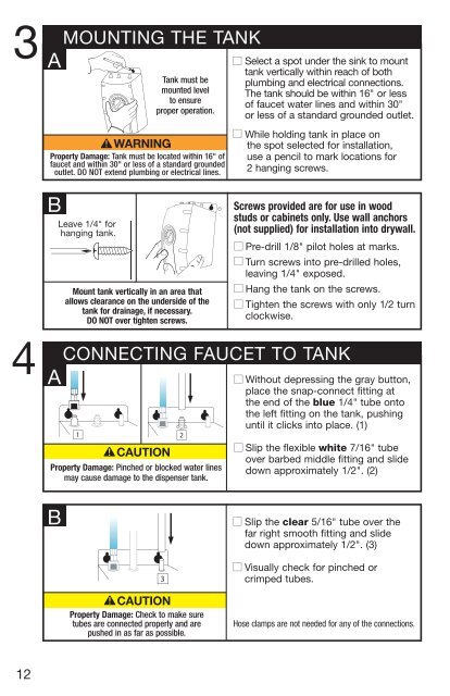
3<br />
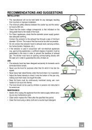
MOUNTING THE TANK<br />
A<br />
Tank must be<br />
mounted level<br />
to ensure<br />
proper operation.<br />
Property Damage: Tank must be located within 16" of<br />
faucet and within 30" or less of a standard grounded<br />
outlet. DO NOT extend plumbing or electrical lines.<br />
■ Select a spot under the sink to mount<br />
tank vertically within reach of both<br />
plumbing and electrical connections.<br />
The tank should be within 16" or less<br />
of faucet water lines and within 30"<br />
or less of a standard grounded outlet.<br />
■ While holding tank in place on<br />
the spot selected for installation,<br />
use a pencil to mark locations for<br />
2 hanging screws.<br />
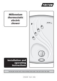
B<br />
Screws provided are for use in wood Brass Nut<br />
studs or cabinets only. Use wall anchors<br />
Leave 1/4" for<br />
hanging tank.<br />
(not supplied) for installation into drywall.<br />
■ Pre-drill 1/8" pilot holes at marks.<br />
■ Turn screws into pre-drilled holes,<br />
leaving 1/4" exposed.<br />
Mount tank vertically in an area that ■ Hang the tank on the screws.<br />
allows clearance 1 on the underside of the 2<br />
■ Tighten the screws with only 1/2 turn<br />
tank for drainage, if necessary.<br />
DO NOT over tighten screws.<br />
clockwise.<br />
FerruleBrass Nut<br />
Brass In<br />
Bras<br />
4<br />
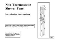
CONNECTING FAUCET TO TANK<br />
A<br />
2<br />
1 2<br />
2<br />
Property Damage: Pinched or blocked water lines<br />
1 may cause damage to the dispenser 2 tank.<br />
3<br />
■ Without depressing the gray button,<br />
place the snap-connect fitting at<br />
the end of the blue 1/4" tube onto<br />
the left fitting on the tank, pushing<br />
until it clicks into place. (1)<br />
■ Slip the flexible white 7/16" tube<br />
over barbed middle fitting and slide<br />
down approximately 1/2". (2)<br />
B<br />
3<br />
3<br />
3<br />
3<br />
■ Slip the clear 5/16" tube over the<br />
far right smooth fitting and slide<br />
down approximately 1/2". (3)<br />
■ Visually check for pinched or<br />
crimped tubes.<br />
Property Damage: Check to make sure<br />
tubes are connected properly and are<br />
pushed in as far as possible.<br />
Hose clamps are not needed for any of the connections.<br />
12