Triton Topaz T100si - Faucets, Showers, Bathroom, Kitchen, More.
Triton Topaz T100si - Faucets, Showers, Bathroom, Kitchen, More.
Triton Topaz T100si - Faucets, Showers, Bathroom, Kitchen, More.
- No tags were found...

Create successful ePaper yourself
Turn your PDF publications into a flip-book with our unique Google optimized e-Paper software.
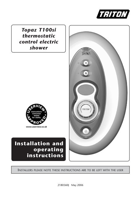
<strong>Topaz</strong> <strong>T100si</strong>thermostaticcontrol electricshowerInstallation andoperatinginstructionsInstallers please note these instructions are to be left with the user2180360J May 2006
<strong>Topaz</strong> <strong>T100si</strong>CONTENTSPageImportant safety information 1Introduction 2Specifications 2Understanding your <strong>Topaz</strong> 2Key to main components 3Electrical requirements 4 − 5Water requirements 6Siting of the shower 7 − 8Fitting the shower to the wall 9Plumbing connections 10Electrical connections 11Commissioning 12 − 13Replacing the cover 13Operating the shower 14 − 16Operating functions 17 − 18Changing the fascia 18Fitting the antler riser rail 19 − 20Fitting the Antler hose and showerhead 20Fitting the arc riser rail 21 − 22Fitting the ARC hose and showerhead 22Adjusting the showerhead 23Cleaning the showerhead 24Cleaning the inlet filter 25Cleaning the scale trap 26Spare parts 27 − 28Fault finding 29 − 30Guarantee, service policy, etc.rear coverTo check the product suitability for commercial and multiple installations, please contact<strong>Triton</strong>’s specification advisory service before installation.Telephone: +44 (0) 24 7632 5491Facsimile: +44 (0) 24 7632 4564E mail: technical@triton.plc.uk
<strong>Topaz</strong> <strong>T100si</strong>Please Read This Important Safety Information Products manufactured by <strong>Triton</strong> are safe and without risk provided they are installed,used and maintained in good working order in accordance with our instructions andrecommendations. WARNING: Do not operate shower if frozen, or suspected of being frozen. It mustthaw out before using. Do not operate the unit if the showerhead or spray hose becomes damaged. Do not restrict flow out of shower by placing showerhead in direct contact with your body. Do not operate the shower if water ceases to flow during use or if water has entered inside1 General1.1 Isolate the electrical and water supplies beforeremoving the cover.1.2 Read all of these instructions and retain themfor later use.1.3 Do not take risks with plumbing or electricalequipment.1.4 Isolate electrical and water supplies beforeproceeding with the installation.1.5 The unit must be mounted onto the finishedwall surface (on top of the tiles). Do not tileup to unit after fixing to wall.1.6 Contact Customer Service (see back page), ifany of the following occur:a) If it is intended to operate the shower atpressures above the maximum or below theminimum stated.b) If the unit shows a distinct change inperformance.c) If the shower is frozen.1.7 If it is intended to operate the shower in areasof hard water (above 200 ppm temporaryhardness), a scale inhibitor may have to befitted. For advice on the <strong>Triton</strong> Scale Inhibitor,contact <strong>Triton</strong> Customer Service.1.8 The showerhead must be cleaned regularlywith descalent to remove scale and debris,otherwise restrictions to the flow on the outletof the unit will result in higher temperaturesand could also cause the Pressure Relief Devicein the unit to operate.1.9 This product is not suitable for mounting intosteam rooms or steam cubicles.2 Plumbing2.1 The plumbing installation must comply withWater Regulations, Building Regulations orany particular regulations as specified by LocalWater Company or Water Undertakers andshould be in accordance with BS 6700.2.2 The supply pipe must be flushed to clear debrisbefore connecting to the shower unit.2.3 Do not solder pipes or fittings within 300mmof the shower appliance, as heat transfer candamage components.2.4 Do not fit any form of outlet flow control asthe outlet acts as a vent for the heater can.2.5 Do not use excessive force when makingconnections to the flexible hose orshowerhead, finger tight is sufficient.2.6 All plumbing connections must be completedbefore making the electrical connections.3 Electrical3.1 The installation must comply with BS 7671‘Requirements for electrical installations’ (IEEwiring regulations), building regulations or anyparticular regulations as specified by the localElectrical Supply Company.3.2 This appliance must be earthed.3.3 In accordance with ‘The Plugs and Sockets etc.(Safety) Regulations 1994’, this appliance isintended to be permanently connected to thefixed wiring of the electrical mains system.3.4 Make sure all electrical connections are tight toprevent overheating.3.5 Fuses do not give personal protection againstelectric shock.3.6 To enhance electrical safety a 30mA residualcurrent device (RCD) should be installed in allUK electric and pumped shower circuits. Thismay be part of the consumer unit or a separateunit.3.7 Switch off immediately at the isolating switch ifwater ceases to flow during use.3.8 Other electrical equipment i.e. extractor fans,pumps must not be connected to the circuitswithin the unit.3.9 Switch off at isolating switch when not in use.This is a safety procedure recommended withall electrical appliances.3.10 As with all electrical appliances it isrecommended to have the shower andinstallation checked at least every two years bya competent electrician to make sure there isno deterioration due to age and usage.
<strong>Topaz</strong> <strong>T100si</strong>INTRODUCTIONThis book contains all the necessary installationand operating instructions for your <strong>Triton</strong> <strong>Topaz</strong><strong>T100si</strong> thermostatic electric shower.Take time to read this book thoroughly andfamiliarise yourself with all instructions beforecommencing installation. Please keep it forfuture reference.The shower installation must be carried out by asuitably qualified person and in the sequence ofthis instruction book.Care taken during the installation will ensure along, trouble-free life from your shower.SpecificationsElectricalNominal power Nominal powerrating at 240V rating at 230V8.5kW – (40A MCB rating) 7.8kW – (40A MCB rating)9.5kW – (40A MCB rating) 8.7kW – (40A MCB rating)10.5kW–(45A MCB rating) 9.6kW – (45A MCB rating)WaterInlet connection – 15mm diameter.Outlet connection – ½” BSP male thread.Entry PointsWater and cable – top, bottom or back.MaterialsBackplate, cover, controls, showerhead – ABS.Sprayplate – Acetal.Elements – Minerally insulated corrosionresistant metal sheathing.DimensionsHeight - 335mmWidth - 225mmDepth - 95mmStandards and ApprovalsWaterproof rating IPX4.Complies with the requirements of currentBritish and European safety standards forhousehold and similar electrical appliances.Complies with requirements of the BritishElectrotechnical Approvals Board (BEAB).Meets with Compliance with EuropeanCommunity Directives (CE).Understanding your topazImportant: When first installed the unitwill be empty. It is essential the unit shouldcontain water before the elements areswitched on. As this unit has electroniccontrol, it is vital that the commissioningprocedure is followed. Failure to carry outthis operation will result in damage to theunit and will invalidate the guarantee.Temperature/flow rateThe temperature control on the unit can beadjusted to provide shower temperaturesnominally between 35°C and 47°C. The unitwill give higher and lower temperatures if givenextreme supply conditions.Note: The maximum flow rate for the giventemperature will be greater in the summerthan in winter because of ambient temperaturevariance of the mains water supply.It is strongly advised to select economy powerduring periods of hot weather, otherwise at allother times, leave the power setting at full toprovide the maximum flow rate.Safety cut-outThe unit is fitted with a non-resettable overtemperaturesafety device. In the event ofabnormal operation which could cause unsafetemperatures within the unit, the device willdisconnect the heating elements. It will require avisit from a qualified engineer to determine thenature of the fault and replace the safety device,once the unit has been repaired.Replacement parts can be ordered from CustomerService. See ‘spare parts’ for details and part numbers.Due to continuous improvement and updating,specification may be altered without prior notice.
<strong>Topaz</strong> <strong>T100si</strong>Fig.1KEY TO MAIN COMPONENTS31017 174597611138112Inside unit (fig.1)1. Top cable/pipe entry2. Bottom cable/pipe entry3. Wall screw fixings4. Power printed circuit board5. Thermal cut-out6. Can and element assembly7. Ribbon cable connector8. Terminal block9. Earth connection10. PRD11. Solenoid valve12. Trim plate13. Thermostatic valve14. Scale trap15. Pressure switch16. Shower outlet17. Guide pockets1415Fig.22NOTE: Notall wires havebeen depicted forreason of clarity1716320 20Inside cover (fig.2)18. Control printed circuit board19. Start/Stop printed circuit board20. Cover tags21. Ribbon cable2118Pack contentsShower unitFive position showerheadRiser rail kitSpray hoseSoap dishScrew fixing kitInstructions, guarantee, etc.1920
<strong>Topaz</strong> <strong>T100si</strong>Electrical requirementsWARNING!This appliance must beearthedThe installation, supply cable and circuitprotection must conform with BS7671 (IEEwiring regulations) and be sufficient for theamperage required.The following notes are for guidance only:1 The shower must only be connected to a230-240V ac supply. If you are installing ashower with a kilowatt rating above 9kW, itis advisable to contact the local electricitysupply company.Shepperton Park,<strong>Triton</strong> Road, Nuneaton,Warwickshire, CV11 4NRPull cordisolating switchFig.3Fig.4 schematic of installation circuit1.1 The electrical rating of the shower is shownon the rating label (fig.3) within the unit.2 Before making any sort of electricalconnection within the installation makesure that no terminal is live. If in anydoubt, switch off the whole installation atthe consumer unit.3 The shower must be connected to its ownindependent electrical circuit. IT MUSTNOT be connected to a ring main, spur,socket outlet, lighting circuit or cookercircuit.3.1 The electrical supply must be adequatefor the loading of the unit and existingcircuits.4 Check your consumer unit (main fuse box)has a main switch rating of 80A or aboveand that it has a spare fuse way which willtake the fuse or miniature circuit breaker(mcb) necessary for the shower (fig.4).4.1 If your consumer unit has a rating below80A or if there is no spare fuse way, thenthe installation will not be straightforwardand may require a new consumer unitserving the house or just the shower.4.2 You will need to contact the localelectricity company. They will check thesupply and carry out what is necessary.They will also check the main bonding.5 The earth continuity conductor of theelectrical installation must be effectivelyconnected electrically to all exposed metalTable ARCD(can be part ofconsumer unit)ShowerunitCircuit protectionunitcartridgerating mcb fuse7.0kW 30/32A 30AFuse orMCB80A or 100Amain switchConsumerunitMetertailsMeterIncomingsupplyfuse7.5kW 32A 35A8.0kW 40A 35A8.5kW 40A 45A9.0kW 40A 45A9.5kW 40/45A 45A10.5kW 45A 45A
<strong>Topaz</strong> <strong>T100si</strong>parts of other appliances and servicesin the room in which the shower is tobe installed, to conform to current IEEregulations.5.1 All exposed metallic parts in the bathroommust be bonded together using a cable ofat least 4mm² cross sectional area. Theseparts include metal baths, radiators, waterpipes, taps and waste fittings.6 For close circuit protection do not use arewireable fuse. Instead use a suitably ratedMCB or cartridge fuse (see table A).6.1 In the interest of electrical safety a 30mAresidual current device (RCD) should beinstalled in all UK electric and pumpedshower circuits. This may be part of theconsumer unit or a separate unit.7 A 45 amp double pole isolating switchwith a minimum contact gap of 3mm inboth poles must be incorporated in thecircuit.7.1 It must have a mechanical indicatorshowing when the switch is in theOFF position, and the wiring must beconnected to the switch without the use ofa plug or socket outlet.7.2 The switch must be accessible and clearlyidentifiable, but out of reach of a personusing a fixed bath or shower, except forthe cord of a cord operated switch, andTable BTwin and earth PVC insulated cablecurrent carrying capacityinstalled in an in conduitinsulated wall or trunkingclipped direct orburied in a noninsulated wall6mm² 6mm ² 6mm²32A 38A 46A10mm² 10mm² 10mm²43A 52A 63A16mm² 16mm² 16mm²57A 69A 85Ashould be placed so that it is not possibleto touch the switch body while standingin a bath or shower cubicle. It should bereadily accessible to switch off after usingthe shower.8 Where shower cubicles are located in anyrooms other than bathrooms, all socketoutlets in those rooms must be protectedby a 30mA RCD.9 The current carrying capacity of the cablemust be at least that of the shower circuitprotection (see table B).9.1 To obtain full advantage of the powerprovided by the shower, use the shortestcable route possible from the consumerunit to the shower.9.2 It is also necessary to satisfy thedisconnection time and thermalconstraints which means that for any givencombination of current demand, voltagedrop and cable size, there is a maximumpermissible circuit length.10 The shower circuit should be separatedfrom other circuits by at least twice thediameter of the cable or conduit.10.1 The current rating will be reduced if thecabling is bunched with others, surroundedby thermal loft or wall insulation or placedin areas where the ambient temperatureis above 30°C. Under these conditions,derating factors apply and it is necessary toselect a larger cable size.10.2 In the majority of installations, thecable will unavoidably be placed in oneor more of the above conditions. Thisbeing so, it is strongly recommendedto use a minimum of 10mm cablingthroughout the shower installation.10.3 In any event, it is essential that individualsite conditions are assessed by a competentelectrician in order to determine thecorrect cable size and permissible circuitlength.Note: Cable selection is dependenton derating factors
<strong>Topaz</strong> <strong>T100si</strong>SITING OF THE SHOWERWARNING!The shower must not be positionedwhere it will be subjected to freezingconditions.Riser rail canbe mounted eitherside of showerImportant: If installing onto a tiled wallalways mount the unit on the surface of thetiles. Never tile up to the unit.Refer to fig.6 for correct siting of the shower.Position the unit where it will not be in directcontact with water from the showerhead.Position the shower unit vertically.Allow enough room between the ceiling and theshower to access the cover top screws.Note: Water regulations require the showerheadbe ‘constrained by a fixed or sliding attachmentso that it can only discharge water at a pointnot less than 25mm above the spill-over levelof the relevant bath, shower tray or other fixedappliance’. The use of the supplied soap dishwill in most cases meet this requirement, but ifthe showerhead can be placed within a bath,basin or shower tray, then a double check valve,or similar, must be fitted in the supply pipeworkto prevent back-flow.IMPORTANT: Using a suitable sealant, alwaysseal around the incoming pipework toprevent water entering the wall.Liquid Crystal DisplayThis shower unit has a LCD which has anoptimum viewing angle that is slightly beloweye level. Therefore position the unit so thedisplay is at nose level. For multiple users ofvarying heights, an optimum shower heightmust be arrived at.SpilloverlevelSoap dishretainingring25mm minimumOutline of bathor shower trayMains cold watersupply - bottom,top and backFig.6 Diagrammatic view (not to scale)Height ofsprayheadandshowerto suituser'srequirementShower unitmust notbe withinan area1 metrefrom baseImportant: The unit must be mountedon a flat surface which covers the fullwidth and length of the backplate,otherwise difficulty may arise when fittingthe cover and subsequent operation ofthe unit may be impaired.Pressure relief safety deviceA pressure relief device (PRD) is designed intothe shower unit which complies with Europeanstandards. The PRD provides a level of applianceprotection should an excessive build up ofpressure occur within the shower.Do not operate the shower with a damaged orkinked shower hose, or a blocked showerhead
<strong>Topaz</strong> <strong>T100si</strong>Fig.7which can cause the PRD to operate.Make sure the PRD outlet at the bottom of theunit is not blocked (fig.7).Area to keep clearWarning!If using a silicon seal around thebackplate edge, make sure the PRDexit behind the outlet pipe is keptclear.Fig.8When commissioning, the showerhead must beremoved from the flexible hose. Failure to followthis procedure may cause the PRD to operate.Make sure the shower is positioned over a bathor shower tray because if the PRD operates, thenwater will eject from the bottom of the unit.Should this happen, turn off the electricity‐andwater supplies to the shower at the isolatingswitch and stopvalve. Contact Customer Servicefor advice on replacing the PRD.Fig.9
<strong>Topaz</strong> <strong>T100si</strong>FITTING THE SHOWER TO THE WALLNote: The control knob is an integral part ofthe cover — do not attempt to remove it.Unscrew the two top and one bottom retainingscrews. There is no need to completely removethe screws, just enough to lift the cover fromthe backplate. To allow access to the pipe andcable connections remove the trimplate bylifting away from the backplate.Entry positions for the mains water are from thetop, bottom or back. Cable entry is via the top,bottom or back.Note: Deviations from the designated entrypoints will invalidate product approvals.If bottom surface entry is required, then thenecessary hole will need to be cut out in the‘thinned section’ of the trimplate using a juniorhacksaw and file (fig.8).If bottom or rear entry is chosen, the pipe trimwill need to be fitted in the top entry positionon the backplate (fig.9).If installing a supply pipe from the rear orbottom, the centre of the inlet valve to the wallsurface is 21mm (fig.10).Note: If entry is from the rear, the nut of thecompression fitting will be partially behind thesurface of the wall. This area must be left clearwhen plastering over the pipework in order tomake the nut accessible for future adjustments.After choosing the site for the shower, use thebackplate as a template and mark the three wallfixing holes (fig.11). Drill and plug to suit thefixing screws supplied. (The wall plugs provided aresuitable for most brick walls — use an appropriatemasonry drill, but if the wall is plasterboard or a softbuilding block, you must use suitable wall plugs andan appropriate drill bit).Screw the top left-hand fixing screw intoposition leaving the base of the screw headprotruding 6mm out from the wall.Hook the backplate over this screw, then fit theother two fixing screws into position.Do not fully tighten the screws at this stage,as the fixing holes are elongated to allow forout of square adjustment after the plumbingconnections have been completed.21mmFig.10Fig.11
<strong>Topaz</strong> <strong>T100si</strong>Fig.12warning!InletfilterThe outlet of the shower acts as avent and must not be connected toanything other than the hose andshowerhead supplied.PLUMBING CONNECTIONSPlumbing to be carried out before wiringDo not use jointing compounds on any pipefittings for the installation.Do not solder fittings near the shower unitas heat can transfer along the pipework anddamage components.Compression fittings must be used to connectto the inlet of the shower.Note: An additional stopvalve (complying withWater Regulations) must be fitted in the mainswater supply to the shower as an independentmeans of isolating the water supply shouldmaintenance or servicing be necessary.Important: Before completing theconnection of the water supply to the inletof the shower, and in compliance with WaterRegulations, flush out the pipework to removeall swarf and system debris. This can beachieved by connecting a hose to the pipeworkand turning on the mains water supply longenough to clear the debris to waste.ProcedureTurn off the water supply either at the mainsstopvalve or the isolating stopvalve. Connectthe mains water supply to the inlet (fig.12)of the shower via 15mm copper, stainless steelor plastic pipe using a 15mm x 15mm elbowcompression fitting. The plastic filter protrudesfrom the inlet so check it is in place beforeconnection.The compression fitting must be pushedfully home onto the inlet to make sure of fullengagement.Note: The inlet fitting is designed to enter acompression fitting only. Do not use pushfit connectors as full engagement cannot beguaranteed. Do not use excessive force whenmaking these connections.Make sure the backplate is square on the walland tighten the three retaining screws whichhold it to the wall. Check the backplate is notdistorted when screws are fully tightened.Turn on the mains water supply and check forleaks in the pipework connection to the shower.10
<strong>Topaz</strong> <strong>T100si</strong>Note: At this stage no water can flow throughthe unit.Fig.13ELECTRICAL CONNECTIONSSwitch off the electricity supply atthe mains.Fig.13 shows a schematic wiring diagram.The cable entry points are top, bottom or back.The cable can be surface clipped, hidden or via20mm conduit.Note: Conduit entry can only be from rear.Route the cable into the shower unit andconnect to the terminal block as follows:LNETerminalblockStart/stopswitchEarthpostControlPCBThermalcut-outPressureswitch ThermistorPowerPCBConnectorsocketEarth cable to terminal marked ENeutral cable to terminal marked NLive cable to terminal marked LImportant: Fully tighten the terminal blockscrews and check that no cable insulation istrapped under the screws. Loose connectionscan result in cable overheating.Note: The supply cable earth conductor mustbe sleeved. The outer sheath of the supply cablemust be stripped back to the minimum.The supply cable must be secured either byrouting through conduit or in trunking or byembedding in the wall, in accordance withcurrent IEE regulations.The use of connections within the unit to supplypower to other equipment i.e. extractor fans,pumps etc. will invalidate the guarantee.DO NOT switch on the electricitysupply until the cover has been fitted.Note: The elements on UK models are to 240Vspecifications and will give a lower kW rating ifthe voltage supply is below 240V.outletElementsinletSolenoidvalve11
<strong>Topaz</strong> <strong>T100si</strong>Fig.14Fig.15ValvespindleWARNING!Before normal operation of theshower, it is essential the followingcommissioning procedure iscompleted correctly.CommissioningThe first operation of the shower is intended toflush out any remaining system debris and tomake sure water is purged through the unit sothat the heater unit contains water before theelements are switched on.Refit the trimplate by carefully guiding into thelocating slots in the backplate.At this stage, the cover is temporarily fitted inorder to carry out the commissioning procedure.a) Offer the cover to the unit. Do not connectthe 14-way ribbon cable at this stage.b) Make sure the valve spindle has the ‘flat’ andkeyway slot uppermost (12 o’clock position).See fig.14.c) Make sure the temperature control knobon the cover has ‘TRITON’ horizontal withthe blue/red graphics at the top - the knob‘flat’ inside the cover should be uppermost(fig.15).d) Carefully locate the cover tags into the guidepockets on the backplate and check the wiresare not trapped.e) Guide into position so that the control spindlelocates correctly (the ‘flats’ only allow thespindle and knob only fit one way).Should any difficulty arise, recheck the pointsabove.While applying slight pressure to the frontcover, secure in position with the three retainingscrews.Fit the flexible hose (but without theshowerhead) to the shower outlet, with theoutlet of the hose directed to waste. Check thesupplied sealing washer is in place.Turn on the water supply to the shower at theisolating stopvalve. Switch on the electricitysupply to the shower at the isolating switch.Water will start to flow through the unit anddischarge from the flexible hose.It will take about thirty seconds for a smoothflow of water to be obtained while air and anydebris is being flushed from the shower. Whena smooth flow of water is obtained, disconnectthe electricity supply to the shower at theisolating switch. This will stop the water flow.12
<strong>Topaz</strong> <strong>T100si</strong>Unscrew the cover retaining screws again andlift the cover from the backplate.Attached to the control PCB, inside the cover,is a 14-way ribbon cable. The ribbon cableconnector must be plugged into the socketlocated on the power PCB inside the unit(fig.16). The connector can only be correctlyplugged in one way by virtue of a locationlug on the plug. The ribbon cable also has acoloured edge which is on the right-hand sidewhen correctly fitted to the socket.Fig.16REPLACING THE COVERImportant: Before finally fitting the cover,the following steps must be taken:a) Check all plumbing connections are watertight.b) Check terminal block screws are fullytightened.c) Make sure the pipe and cable entering theunit do not prevent the cover locatingcorrectly to the backplate.d) Make sure the valve spindle has the ‘flat’and keyway slot uppermost (12 o’clockposition).e) Make sure the temperature control knobon the cover has ‘TRITON’ horizontalwith the blue/red graphics at the top(the knob ‘flat’ inside the cover should beuppermost).Offer the cover to the unit. Carefully locatethe cover tags into the guide pockets on thebackplate and check the wires are not trapped.Guide into position so that the control spindlelocates correctly (the ‘flats’ only allow thespindle and knob will only fit one way). Whileapplying slight pressure to the front cover,secure in position with the three retainingscrews.The flexible hose can be left attached to theshower outlet. Make sure the supplied sealingwasher is fitted.Once the riser rail kit is installed, the shower isready for normal operation.13
<strong>Topaz</strong> <strong>T100si</strong>Fig.17Power buttonCold buttonOPERATING THE SHOWERWARNING!Before normal operation of theshower, it is essential that thecommissioning procedure has beencompleted correctly.Fig.18Fig.19Fig.20DisplayTemperaturecontrolStart/StopbuttonThe shower controls are shown in fig.17.Caution: It is recommended that personswho may have difficulty understanding oroperating the shower controls should notbe left unattended while using the shower.Special consideration should be given toyoung children and the less able bodied.Make sure the water supply is turned fully on.Switch the electric supply back on at theisolating switch.Immediately, the start up routine commencesand the display flashes all information for threeseconds (fig.18).The display then shows ‘OK’ in a blue backlight(fig.19). It will remain in this standby modeuntil the shower is started.To start the showerPress the Start/Stop buttonflow.and water willThe display shows ‘FUL’ (fig.20) indicating fullpower is being used.After a few seconds, two ‘up arrows’ startflashing indicating the unit is working towardsits preset showering temperature (fig.21). Thisis achieved shortly when the display shows thetemperature as °C.To stop the showerPress the Start/Stop button and the phasedshutdown will begin. The current temperatureand segments are replaced with a flashing ‘SD’and ‘Shutting Down’ alternating on thedisplay (fig.22). Water stops flowing after a fewseconds after which the display returns to ‘OK’.The shower can be left in this standby modeready for the next immediate user, otherwise,switch off at the isolating switch.14
<strong>Topaz</strong> <strong>T100si</strong>Control buttonsApart from the Start/Stop button, there aretwo other control buttons — power and cold.The button marked is for cold water only.When pressed the current display is replacedby ‘CLD’ (fig.23). It remains in this state untilthe power button is pressed. Adjusting thetemperature control at this setting has no effecton the force of the water from the showerhead.The button marked is the power buttonwhich is a toggle switch between full power andeconomy power.Economy is for using less power when theambient mains water temperature is high duringhot months.If the shower is on full power and the powerbutton is pressed, the current display is replacedby ‘ECO’ for five seconds (fig.24). During thistime, the flow rate decreases to try to achievethe same temperature as before.Note: If the setting was high at full power,then it will not be possible to obtain the sametemperature on economy power. The showerwill try to provide the highest temperature atthe best flow rate.Note: If the stated flow rate required for theunit cannot be met due to low water pressure,it will be necessary to operate the shower oneconomy power during hot months because offlow rate limitations entering the unit.Full is the maximum power setting which allowsthe highest flow achievable for your preferredtemperature.If the shower is on economy power or the coldsetting and the power button is pressed,thecurrent display is replaced by ‘FUL’ for fiveseconds (fig.25). During this time, the flowrate increases to achieve the same temperatureas before or to correspond to the currenttemperature control position.It is advisable to leave the power setting atfull at all times, except during periods of hotweather.Fig.21Fig.22Fig.23Fig.24Fig.2515
<strong>Topaz</strong> <strong>T100si</strong>Fig.26Fig.27Fig.28Fig.29To adjust the shower temperatureThe showering temperature is varied by turningthe temperature control which changes themix of hot water coming from the heater canand the incoming cold water. On the displaycircumference are eleven outer segments whichrepresent the total angular movement of thetemperature control. Rotating the temperaturecontrol causes inner segments to fill, indicatingthe actual position of the control relative to itsminimum and maximum limits.Minimum temperature (fig.26) position (oneinner segment full that corresponds to thecontrol position).Maximum temperature (fig.27) position (allinner segments full that corresponds to thecontrol position).To decrease the shower temperatureTurn the temperature control anti-clockwise; thecurrent temperature display is replaced by twoflashing ‘down arrows‘ (fig.28). Five secondslater the display shows the revised temperature.To increase the shower temperatureTurn the temperature control clockwise; thecurrent temperature display is replaced by twoflashing ‘up arrows‘ (fig.29). A few secondslater the display shows the revised temperature.Note: It is advisable to be certain that theshowering temperature is satisfactory by testingwith your hand before stepping under theshowerhead.There will always be a time delay of a fewseconds between selecting a temperatureand the water reaching the stable selectedtemperature.16
<strong>Topaz</strong> <strong>T100si</strong>OPERATING FUNCTIONSClean showerheadAfter a preset number of Start/Stop buttonoperations (nominally 75), the start up routineacts as normal but instead of a blue ‘OK’ thedisplay backlight turns red and a flashing ‘CS’alternating with a flashing ‘showerhead symbol’and ‘CLEAN’ appear (fig.30).This is a reminder to clean the showerhead. Itdoes not indicate a defect to the shower.To remove the red ‘CS’ from the display, pressthe power and cold buttons simultaneously forthree seconds. Alternatively you can choosenot to remove the flashing indication and carryon by pressing the Start/Stop button andshowering as normal, but the ‘symbol’ and‘CLEAN’ will continue to flash at the side of the°C figure for a further five shower operationsafter which time it will stop (whether you cleanthe showerhead or not). The shower will thenreset automatically for a further preset numberof shower operations before flashing thereminder again.Fig.30Fig.31Low pressureWhen the display backlight turns red and‘LP’ and ’low pressure’ flash alternately, itmeans the water pressure has fallen below theminimum required for correct operation of theshower (fig.31). This causes the low pressureswitch to operate and this turns off power tothe heating elements preventing any maintainedtemperature rises. Water will no longer flow untilthe unit has been reset.Press the Start/Stop button once to reset theshower. The shower will shut down and thenbegin its start up routine.If there is still not enough pressure for correctoperation the ‘low pressure’ display will flashonce more and the shower will require resettingagain.If there is enough pressure the display willchange to show ‘ok’ in a blue backlight and theshower will run as normal.17
<strong>Topaz</strong> <strong>T100si</strong>Fig.32WARNING!After any servicing of mains watersupply, always make sure the unit isstarted on COLD in order to purge anyair in the pipework.Phased shutdownIn use, when the Start/Stop button is pressed,power is switched off to the elements and thepower indicator will extinguish. The displaywill change to a flashing ‘SD’. Water continuesto flow for a few seconds, flushing out anyremaining hot water. This makes sure the nextimmediate user will not receive a slug of hotwater if standing under the showerhead whenstarting the shower.Safety cut-outThe shower is fitted with a thermal cutoutsafety device. In the event of abnormaloperation which could cause unsafetemperatures within the unit, the device willdisconnect the heating elements.It will require a visit from a qualified engineerto determine the nature of the fault and replacethe safety device, once the unit has beenrepaired.Changing the fasciaThis shower unit has the facility for the colouredfascia to be simply changed for another colourof your choice. The coloured options areavailable as low cost accessories and are listed inthe ‘parts list’ section at the rear of this booklet.The top of the fascia has a recessed cutaway.With your finger, just press down in the cutawayand pull away (fig.32). To replace the fascia,position the lower end into the recess of thecover and push fit the top into position.Note: In normal use, it is in order to leave thewater supply permanently on to the showerunit, but as with most electrical appliances,the unit must be switched off at theisolating switch when not in use.18
<strong>Topaz</strong> <strong>T100si</strong>FITTING THE ANTLER RISER RAILWarning!Check there are no hidden cables orpipes before drilling holes for wallplugs. Use great care when usingpower tools near water. The use ofa residual current device (RCD) isrecommended.Decide the position for the rail on the wallwithin the shower area and proceed as follows:The showerhead holder is supplied alreadyattached to the rail unit and the angle of theholder dictates the rail top and bottom. Thecorrect orientation of the rail is when the holderis sloping down.Offer the rail to the wall, and mark the twoelongated upper holes and the elongated lowertwo holes.Do not use the square edged holes (fig.33).These are for fitting the lug when sliding thefinishing trims into position.Make sure the rail is aligned vertically then drilland plug the wall. (The wall plugs provided aresuitable for most brick walls — use an appropriatemasonry drill, but if the wall is plasterboard or asoft building block, use suitable wall plugs and anappropriate drill bit).Secure to the wall with the screws supplied,making sure the showerhead holder is slopingdown.Slide the finishing trims onto the riser railbracket ends (fig.34). Make sure the trimlug slides behind the rail bracket and engagescorrectly between the wall and bracket.Adjusting the showerhead holderThe holder is supplied already attached to therail unit. To adjust the height, slightly lift theholder arm (fig.35) to unlock it (an audibleclick denotes it is unlocked).Slide the holder arm up or down on the ratchetmechanism to suit user’s requirement.To lock the holder arm in position, push the armdown until it ‘clicks’ (fig.36).Fig.33Fig.34Fig.35Fig.3619
<strong>Topaz</strong> <strong>T100si</strong>Fig.37Fig.38Fig.39ShoweroutletSprayheadFitting the soap dishCarefully squeeze the soap dish ends slightly inorder to open up the engagement side of thedish (fig.37). Guide the dish onto the lowerend of the rail while still squeezing the dish endstogether.It will snap into position when located correctly,following the same contours as the rail bracket.Fitting the hose andshowerheadFeed the flexible hose through the appropriatesoap dish opening (fig.38) so the dish acts as aretaining ring (Water Regulations).Screw the flexible hose to the shower outlet andshowerhead (fig.39), making sure the suppliedwashers are in place at both ends of the flexibleshower hose.Place the showerhead into the holder and checkthat it fits correctly.Note: The holder is slightly tapered and theshowerhead and hose will only fit from onedirection.Important: It is the conical end of the hosewhich grips into the holder. The showerheadwill not fit in the holder without the hoseattached.Washers20
<strong>Topaz</strong> <strong>T100si</strong>Fitting the ARc riser railWarning!Check there are no hidden cables orpipes before drilling holes for wallplugs. Use great care when usingpower tools near water. The use ofa residual current device (RCD) isrecommended.Fig.40Fig.41Fig.42Decide the position for the rail on the wallwithin the shower area. Proceed as follows:Fit the showerhead holder onto the riser rail.The correct position of the holder is when theshowerhead holder is sloping down (fig.40).To fit the showerhead holder onto the riserrail unit, press and hold the button on theunderneath of the showerhead holder to releasethe locking mechanism, then slide onto the rail.Slide the supplied soap dish onto the riser railbelow the showerhead holder (fig.41).Slide the top and bottom finishing trims ontothe riser rail (fig.42).Push the two fixing brackets into the ends of theriser rail (fig.43).Offer the rail assembly to the wall (fig.44).Using the brackets as templates, mark two upperholes and two lower holes.Note: There are four provisions for screws perbracket — select the two most suitable for yourrequirements and make sure the rail is alignedvertically.Drill and plug the wall. (The wall plugs providedare suitable for most brick walls — use anappropriate masonry drill, but if the wall isplasterboard or a soft building block, use suitablewall plugs and an appropriate drill bit).Screw to the wall with the fixing screwssupplied.Slide the finishing trims onto the brackets. Makesure the lug on each rail bracket end engagesinto the slot on the fatter end of each trimbefore push fitting the thinner ends in place(fig.45).To remove a trim, push a small screwdriver orFig.44Fig.4321
<strong>Topaz</strong> <strong>T100si</strong>Fig.45similar through the slot in the trim end andcarefully pull away from the wall bracket.Slide the soap dish down the rail so that itsbracket engages on top of the lower finishingtrim.Adjusting the showerhead holderTo adjust the holder height, press the buttonunderneath the holder to release the lockingmechanism (fig.46). While still pressing thebutton, move the holder up or down to suituser’s requirement and then release.Fig.46Fig.47Fitting the hose andshowerheadFeed the flexible hose through the soap dishopening (fig.47) so the dish acts as a retainingring (Water Regulations).Screw the flexible hose to the shower outlet andshowerhead, making sure the supplied washersare in place at both ends of the flexible hose(fig.48).Place the showerhead into the holder and checkthat it fits correctly (fig.49).Fig.48ShoweroutletWashersSprayheadNote: The holder is slightly tapered and theshowerhead and hose will only fit from onedirection.Important: It is the conical end of the hosewhich grips into the holder. The showerheadwill not fit in the holder without the hoseattached.Fig.49ShowerheadHolder22
<strong>Topaz</strong> <strong>T100si</strong>ADJUSTING THE SHOWERHEADFive showerhead patterns are available (fig.50).Adjust the spray pattern by turning the bezelon the showerhead in either direction until thedesired pattern is obtained.Fig.5023
<strong>Topaz</strong> <strong>T100si</strong>Fig.51SprayplatekeyCLEANING THE SHOWERHEADWARNINGDo not use ‘powerful’ abrasive orsolvent cleaning fluids when cleaningthe shower as they may damage theplastic fittings.Fig.52SprayplateBefore cleaning, turn off the unit at theisolation switch to avoid the shower beingaccidentally switched on.It is important to keep the showerheadclean to maintain the performanceof the shower. The hardness of the waterwill determine the frequency of cleaning. Forexample, if the shower is used every day in avery hard water area, it may be necessary toclean the showerhead on a weekly basis.Sprayplate removalThere is no need to remove the showerheadfrom the hose.Using the removal tool supplied (fig.51),locate the raised bosses into the recesses inthe sprayplate. Hold in firmly and twist anticlockwise(fig.52). This movement may turn thecartridge assembly as well until it reaches a ‘stop’.Hold the cartridge firmly and continue to twistanti-clockwise. Having loosened the sprayplate,it can be unscrewed and removed completely.Clean the sprayplate with a suitable brush orpreferably leave it to soak overnight in a mildproprietary descalent. Make sure all traces ofscale are removed and thoroughly rinse in cleanwater afterwards.Before replacing the sprayplate, switch thepower back on at the isolating switch and directthe hose and showerhead to waste.Press the Start/Stop button and then pressthe Cold button. This operation will flushout any loose scale deposits in the unit andshowerhead. Stop after about thirty seconds.Refit the sprayplate by screwing clockwise. Usethe tool to screw the sprayplate tight.24
<strong>Topaz</strong> <strong>T100si</strong>Instructions for installers and service engineers onlyCleaning the inlet filterIt is recommended that the filter is periodicallycleaned in order to maintain the performanceof the shower. It is essential that this operationis carried out by a competent person.Switch off the electricity supply atthe mains.Remove the cover. The inlet filter is situated inthe solenoid inlet (fig.53) and can be removedto clean.To gain access to the filter will require thetrimplate to be removed and disconnectionand removal of the compression fitting.Also, depending on the incoming pipeworkarrangements, if there is not enough slack inthe pipework, it could mean the removal of theunit from the wall.When cleaning the plastic filter, do not usea sharp object, as it will cause damage. It ispreferable to use an old toothbrush or similar.Fig.53Inletfilter25
<strong>Topaz</strong> <strong>T100si</strong>instructions for installers and service engineers onlyFig.54Cleaning the scale trapIt is recommended in hard water areas, thescale trap is periodically cleaned to maintain theperformance of the shower.It is essential that this operation is carried out bya competent person.Switch off the electricity supply atthe mains.Remove the cover and unplug the ribbon cable.The scale trap is located at the lower left-handside of the unit. Unscrew the single centralscrew (fig.54) then pull off the cap completewith ‘O’ rings.Be aware of water discharging as the heater canexhausts.Clean out the trap and remove all sediment.Flush the can through by leaving the cap off andswitching on the power at the isolating switch.Note: Check the water that flows out of thescale trap will safely flow to waste.Switch the power off at the isolating switch.Replace the cap, making sure the ‘O’ rings arein place and free from debris. Secure with thecentral screw.Switch the power back on again at the isolatingswitch to enable the can to fill with water. Checkfor water leakage at the scale trap. When waterflows smoothly from the showerhead, stop theflow by switching the power off at the isolatingswitch.Reconnect the ribbon cable and replace thecover and secure with the three screws.26
<strong>Topaz</strong> <strong>T100si</strong>Ref. DescriptionPart No.spare Parts1. Printed circuit boardPower 8.5kW & 9.5kW 7073034Power 10.5kW 707316922. Copper bus bar 702300513. Terminal block & wires S07710900Terminal block 2200114104. Heater can assembly 8.5kWc/w restrictor & TCOHeater can assembly 9.5kWc/w restrictor & TCOHeater can assembly 10.5kWc/w restrictor & TCO833070808330709083307100– Restrictor 8.5kW 22010400– Restrictor 9.5kW 22010310– Restrictor 10.5kW 220104105. Solenoid valve assemblyand ‘O’ ring833071106489537106. Pressure Relief Device 828004507. Trimplate 70529898. Can brace 705300811139. Thermostatic valveand ‘O’ rings (4)8330713010. Connecting tube 2201026012151411. Scale trap coverc/w ‘O’ rings and screw8330714012. Display thermistor 2201030013. Pressure switch microswitch& wiresP0771090414. Pressure switchand ‘O’ ring8330712015. Outlet pipe assembly S0771100027
<strong>Topaz</strong> <strong>T100si</strong>Spare partsRef. DescriptionPart No.161817– Cover assemblyc/w control PCB,start/stop pcb, knobs& buttons– Wire set2 x earth & 1 x solenoidwires8330716083307150– Power PCB carrier 7052991– Rubber microswitch cover 7063046– Inlet filter 705300916. Coloured fasciasSeasprayaquaazurelilacMidnightChromeTSTZFSEATSTZFAQUTSTZFAZUTSTZFLILTSTZFMIDTSTZFCHR192417. 5 mode showerhead – white 2201098018. Flexible hose – white 28100020Arc kit19. Brackets (pair) 220104302120. Trims (pair) – white 2201044021. Riser rail – white 22010450222522. Showerhead holder – white 2201046023. Soap dish 22010470Antler kit24. Trims (pair) – white 2201048025. Riser rail and holder assembly 22010490white26. Soap dish 22010500232628
<strong>Topaz</strong> <strong>T100si</strong>Fault FindingIMPORTANT: Switch off the electricity at the mains supply and remove the circuit fuse beforeattempting any fault finding inside the unit.Problem/Symptom Cause action/Cure1 Showerinoperable.1.1 Interrupted powersupply.1.2 Unit malfunction.1.1.1 Blown fuse or circuit breaker. Checksupply. Renew or reset fuse or circuit breaker. Ifit fails again, consult a qualified electrician.1.1.2 Power cut? Check other appliances and ifnecessary, contact local Electric Supply Co.1.2.1 Have unit checked by suitably qualifiedelectrician or contact Customer Service.2 Water flows whenisolating switch isswitched on.2.1 Ribbon cable is notconnected.2.2 Unit malfunction.2.1.1 Switch off the electric supply, remove theshower cover and plug in ribbon cable.2.2.1 Contact Customer Service.3 Water too hot.3.1 Temperature controlincorrect setting.3.2 Unit malfunction.3.1.1 Turn anti-clockwise.3.2.1 Contact Customer Service.4 Unstable showertemperature orflow.4.1 Blockages.4.2 Loose ribbon cableconnection.4.3 Unit malfunction.4.1.1 Clean showerhead. Check inlet filter.4.2.1 Check connections on PCB.4.3.1 Contact Customer Service.5 Water too cool orcold.5.1 Temperature controlincorrect setting.5.2 Unit malfunction.5.3 Safety cut-outoperated.5.1.1 Turn clockwise.5.2.1 Contact Customer Service.5.3.1 The thermal safety cut-out device hasoperated. Have unit checked by suitablyqualified electrician or contact Customer Service.6 ‘LP’ flashing ondisplay.6.1 Water pressure hasdropped below minimumrequired.6.2 Blockage in outlet.6.3 Loose connection onPCB.6.4 Blocked connectingtube to pressure switch.6.1.1 Wait until water pressure has returned tonormal.6.2.1 Check and clean outlet and/orshowerhead.6.3.1 Check connection on PCB from pressureswitch.6.4.1 Make sure the tube from solenoid valve topressure switch is not kinked or blocked.29
<strong>Topaz</strong> <strong>T100si</strong>Fault Finding (continued)Problem/Symptom Cause action/Cure7 Water continuesto flow whenunit is isolated atisolating switch.7.1 Debris in solenoid.7.1.1 Contact Customer Service for advice.8 Pressure reliefdevice hasoperated (waterejected from PRDtube).8.1 Blocked showerhead.8.2 Twisted/blockedflexible shower hose.8.3 Showerheadnot removed whilecommissioning.8.1.1 Clean or replace blocked showerheadcartridge and then fit a new PRD.8.2.1 Check for free passage through hose.Replace the hose if necessary, then fit new PRD.8.3.1 Fit new PRD. Commission unit withshowerhead removed.It is advised all electrical maintenance/repairs to the showershould be carried out by a suitably qualified person.Note: Identify cause of operation before fitting new PRD unit.When fitting a new PRD, follow the commissioning procedure.30
<strong>Topaz</strong> <strong>T100si</strong>31
<strong>Topaz</strong> <strong>T100si</strong>32
<strong>Topaz</strong> <strong>T100si</strong>33
Service PolicyIn the event of a complaint occurring, thefollowing procedure should be followed:1 Telephone Customer Service on +44 (0) 247637 2222 (+44 (0) 84 5762 6591 in Scotlandand in Northern Ireland), having available themodel number and power rating of the product,together with the date of purchase.2 <strong>Triton</strong> Customer Service will be able to confirmwhether the fault can be rectified by either theprovision of a replacement part or a site visitfrom a qualified <strong>Triton</strong> service engineer.3 If a service call is required the unit must be fullyinstalled for the call to be booked and the dateconfirmed. In order to speed up your request,please have your postcode available whenbooking a service call.4 It is essential that you or an appointedrepresentative (who must be a person of 18 yearsof age or more) is present during the serviceengineer's visit and receipt of purchase is shown.5 A charge will be made in the event of anaborted service call by you but not by us, orwhere a call under the terms of guarantee hasbeen booked and the failure is not productrelated (i.e. scaling and furring, incorrect waterpressure, pressure relief device operation,electrical installation faults).6 If the product is no longer covered by theguarantee, a charge will be made for the site visitand for any parts supplied.7 Service charges are based on the accountbeing settled when work is complete, theengineer will then request payment for theinvoice. If this is not made to the serviceengineer or settled within ten working days, anadministration charge will be added.Replacement Parts PolicyAvailability: It is the policy of <strong>Triton</strong> to maintainavailability of parts for the current range ofproducts for supply after the guarantee hasexpired. Stocks of spare parts will be maintainedfor the duration of the product’s manufactureand for a period of five years thereafter.In the event of a spare part not being available asubstitute part will be supplied.Payment: The following payment methods canbe used to obtain spare parts:1 By post, pre-payment of pro forma invoice bycheque or money order.2 By telephone, quoting credit card (MasterCardor Visa) details.3 By website order, www.tritonshowers.co.uk<strong>Triton</strong> Plc<strong>Triton</strong> RoadNuneatonWarwickshire CV11 4NR<strong>Triton</strong> Standard Guarantee<strong>Triton</strong> Plc guarantee this product against allmechanical and electrical defects arising fromfaulty workmanship or materials for a period oftwo years for domestic use only, from the dateof purchase, provided that it has been installedby a competent person in full accordance withthe fitting instructions.Any part found to be defective during thisguarantee period we undertake to repair orreplace at our option without charge so long asit has been properly maintained and operated inaccordance with the operating instructions, andhas not been subject to misuse or damage.This product must not be taken apart, modifiedor repaired except by a person authorisedby <strong>Triton</strong> Plc. This guarantee applies onlyto products installed within the UnitedKingdom and does not apply to products usedcommercially. This guarantee does not affectyour statutory rights.What is not covered:1 Breakdown due to: a) use other thandomestic use by you or your resident family;b) wilful act or neglect; c) any malfunctionresulting from the incorrect use or quality ofelectricity, gas or water or incorrect setting ofcontrols; d) faulty installation.2 Repair costs for damage caused by foreignobjects or substances.3 Total loss of the product due to nonavailabilityof parts.4 Compensation for loss of use of the productor consequential loss of any kind.5 Call out charges where no fault has beenfound with the appliance.6 The cost of repair or replacement of pressurerelief devices, showerheads, hoses, riser railsand/or wall brackets, isolating switches,electrical cable, fuses and/or circuit breakers orany other accessories installed at the same time.7 The cost of routine maintenance,adjustments, overhaul modifications or loss ordamage arising therefrom, including the costof repairing damage, breakdown, malfunctioncaused by corrosion, furring, pipe scaling,limescale, system debris or frost.Customer Service: +44 (0) 24 7637 2222Scottish and Northern IrelandCustomer Service: +44 (0) 84 5762 6591Trade Installer Hotline: +44 (0) 24 7632 5491Fax: +44 (0) 24 7632 4564www.tritonshowers.co.ukE mail: technical@triton.plc.uk