Monsoon Universal Single Installation Guide - Taps4Less.com
Monsoon Universal Single Installation Guide - Taps4Less.com
Monsoon Universal Single Installation Guide - Taps4Less.com

You also want an ePaper? Increase the reach of your titles
YUMPU automatically turns print PDFs into web optimized ePapers that Google loves.
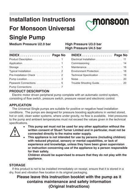
<strong>Installation</strong> InstructionsFor <strong>Monsoon</strong> <strong>Universal</strong><strong>Single</strong> PumpMedium Pressure U2.0 barHigh Pressure U3.0 barHigh Pressure U4.5 barINDEX . . . . . . . . . . . . . . . . Page NoProduct Description . . . . . . . . . . . . . . . . . . . 1Application . . . . . . . . . . . . . . . . . . . . . . . . . . 1Storage . . . . . . . . . . . . . . . . . . . . . . . . . . . . 1Typical <strong>Installation</strong> . . . . . . . . . . . . . . . . . . . . 2Pre-<strong>Installation</strong> Check . . . . . . . . . . . . . . . . 2Pump Location. . . . . . . . . . . . . . . . . . . . . . . 3Pipework Connections . . . . . . . . . . . . . . . . . 5Pump Connections . . . . . . . . . . . . . . . . . . . 7INDEX . . . . . . . . . . . . . . . . Page NoElectrical <strong>Installation</strong> . . . . . . . . . . . . . . . . . . 11Commissioning . . . . . . . . . . . . . . . . . . . . . . 14Maintenance . . . . . . . . . . . . . . . . . . . . . . . . 16Environment Protection . . . . . . . . . . . . . . . . 18Technical Specifi cation . . . . . . . . . . . . . . . . 19Noise . . . . . . . . . . . . . . . . . . . . . . . . . . . . . . 20Trouble Shooting <strong>Guide</strong> . . . . . . . . . . . . . . . . 20PRODUCT DESCRIPTIONElectric motor driven peripheral pump <strong>com</strong>plete with an automatic control system,consisting of flow switch, pressure switch, pressure vessel and electronic control.APPLICATIONThe <strong>Universal</strong> <strong>Single</strong> pumps are suitable for positive or negative head installationconditions. The pumps are designed for pressure boosting applications in vented stored,hot or cold, clean water systems, where under gravity, no flow is available. Inlet pressuresto the pump and ambient temperatures must not exceed the values given in the technicalspecifications.• This pump set must not be used for any other application without thewritten consent of Stuart Turner Limited and in particular, must not beconnected directly to the mains water supply.• This appliance is not intended for use by persons (including children)with reduced physical, sensory or mental capabilities, or lack ofexperience and knowledge, unless they have been given supervisionor instruction concerning use of the appliance by a person responsiblefor their safety.Children should be supervised to ensure that they do not play with theappliance.STORAGEIf this product is not to be installed immediately on receipt, ensure that it is stored in adry, frost and vibration free location in its original packaging.Please leave this instruction booklet with the pump as itcontains maintenance and safety information(Original Instructions)
TYPICAL INSTALLATION (<strong>Universal</strong> <strong>Single</strong> Pump System)This diagram should be usedfor schematic reference only.NegativeheadThe plumbinginstallationmust <strong>com</strong>ply with the following:The Water Supply (Water Fittings)Regulations 1999.BS6700 and building regulations.Be installed by a <strong>com</strong>petent person.• If in doubt consult StuartTurner Ltd.11112Item 1 = System service valves (not supplied)should be fitted.Item 2 = Flexible hoses <strong>com</strong>plete with integralpump isolating valves (supplied)2 Fig. 1STEP 1: PRE-INSTALLATION CHECKPressure vesselFig. 2The pressure vessel (Fig. 2) is factory fitted to the pump assembly.To eliminate any risk that the vessel has lost its assembly torque and sealing abilityduring transit, it must be checked prior to installation.Tighten the vessel as shown to confirm a secure hand tight connection.Note: Do not overtighten pressure vessel.Cont ...- 2 -
STEP 2: PUMP LOCATIONWARNINGS:• Pump LocationIf possible site the pump in a location where in the unlikely event of awater leak, any spillage is contained or routed to avoid electrics orareas sensitive to water damage.• Care should be taken to protect pump from frost and freezing,particularly when located in a loft installation.• The motor casing can be<strong>com</strong>e hot under normal operating conditions,care should be taken to ensure it cannot be touched during operation.• The pump must not be located where the static pressure on the inletor outlet to the pump is greater than 12 metres (1.2 bar). Should theinstallation exceed these limits, contact Stuart Turner for furtheradvice.The pump must be installed so that the following conditions are met:Locate the pump in a dry, frost free position where it cannot be sprayed with water. Itshould be positioned horizontally on its anti-vibration mounting feet and should not bescrewed down. It should be positioned as close to the water source as possible having aminimum flooded suction head of 0.5 metres at all times.The pump has a side mounted terminal box. Ensure the pump is mounted in a positionto allow easy access to the box if required.Ensure the water flow is in the direction of the arrow that is marked on the flow switchreed clamp (vertically upwards).Typical pump locations are in an airing cupboard, or inside a vanity unit with a smallpurpose built dry and ventilated enclosure. The enclosure should have a minimumclearance of 80 mm (3 ”) between the pump and housing on all sides. The enclosureshould be secure and access should only be available by the use of tools.The anti-vibration mounting feet and flexible hoses which are supplied as standard, area precaution to reduce noise transmission, however care must be taken when mountingthe pump that any noise is not amplified through loose panels, pipework or other mountingmedium.The preferred pump location is at floor level next to the hot water cylinder or a level thatis below the secondary tapping that feeds the pump. This will ensure the pump has accessto an air free water supply which is important for trouble free operation (Figs. 3 & 4).Pump location is also dependent on limitations of the static inlet and outlet heads of theinstallation. For guidance on limitations and re<strong>com</strong>mended location, consult the followingrelevant section for hot or cold water installation.- 3 -Cont ...
Before deciding where to locate the unit, check to ensure the static inlet head (Fig. 4)meets the minimum requirement of 0.5 metres and does not exceed the maximumrequirement stated.The static outlet head (Fig. 4) must also be within the maximum requirement stated.Hot Water <strong>Installation</strong>sIf it is not possible to locate the pump in the preferred area due to site limitations and it isnecessary to position the unit in the loft, or in a position above the secondary tapping thatfeeds the pump, then there is an increased risk of air locks. This risk must be eliminated.The following measure is a suggestion that may over<strong>com</strong>e the problem:A “U” bend or downward loop in the supply pipe to the pump of 350 mm depth beforerising to the pump should ensure the cylinder vents its air up the expansion pipe, not up thepump feed (Fig. 5).Max. inlet head 12 m (8 m U2.0 bar)Min. inlet head 0.5 m200 mmminNegativeheadNote: Ensure watersurface is a minimum of200 mm above highestpoint of inlet pipework atall times to prevent airlocks.Least Preferred PumpLocation (shaded area).Pump located above thehot cylinder can increasethe risk of air locks.350 mmminLeast preferred areaMax. outlet head 12 m (8 m U2.0 bar)Fig. 5STEP 3 PIPEWORK CONNECTIONS (General)WARNINGS:• Ensure pipework to and from pump is independently supported toprevent forces being transferred to inlet and outlet branches of pump.• Do not introduce solder flux to pumps, pump parts or hosesmanufactured from plastic. All solder joints should be <strong>com</strong>pleted andflux residues removed prior to pump connection.• Do not allow contact with oil or cellulose based paints, paint thinnersor strippers, acid based descalents or aggressive cleaning agents.• Never operate pump with inlet and/or outlet isolating valves in theclosed position. Damage will occur!- 5 -Cont ...
• Do not install a non-return valve, or deviceswhich contain non-return valves, in thesuction (inlet) pipework to the pump. Thepump must be free to vent to the supplytanks at all times.It must be ensured that the water storage capacity is sufficient to meet the flow ratesrequired by the pump and any other water using fittings and appliances, which may beoperated simultaneously.As a rule of thumb: assuming a cold water temperature of 10°C and a hot watertemperature of 65°C.• A 6-minute shower using 10 litres/min will consume 40 litres of hot water and 20 litresof cold. This means the total quantity of water used from the cold water storage tankwill be 60 litres (40 + 20).• A 10-minute shower using 15 litres/min will consume 100 litres of hot water and 50litres of cold. This means the total quantity of water used from the cold water storagetank will be 150 litres (100 + 50).The pipework feeds to the storage tank should be of adequate size to ensurereplenishment rate of tanks is sufficient to meet the needs of the pump.Care should be taken in the design of pipework runs to minimise the risk of air locks.To prevent loss of water pressure through pipework use 22 mm pipework throughout.Any bend requirements should be achieved by hand drawing the tube or by the use of theappropriate bend fittings. All pipework should be securely clipped.The flexible hoses supplied incorporate integral isolating valves. These hoses shouldbe fitted in the suction and delivery pipework to enable easy access to the pump whenrequired.InletOutletPipework Connections (Cold)The pump must be supplied with a dedicated feed direct from the cold water storagetank.The supply must be air free and connections of the feed pipe to the tank should be via atank connector, positioned at a slightly lower level (25 mm minimum) than the feed pipe tothe hot water cylinder.- 6 -Fig. 6
Hose to pumpThe pump inlet and outlet ports have factory assembled fittings which are specificallydesigned for connection to the G¾ female running nuts on the flexible hoses. The hoseend is fitted with a rubber sealing washer which is held captive within the nut assembly.Locate the hose into position and screw the nut fully onto the fitting by hand. Finally niptight with a spanner (4/5 Nm) for a water tight seal (do not overtighten).Flexible hose29 mm AFG¾ running nutassemblyReedswitchclampassemblyFig. 8Port fittingRubber sealing washer(captive in nut assembly)Anti-rotation flats28 mm AFNote: When tightening or loosening thehose nut assembly, the anti-rotationflats provided on the inlet and outletfittings should be used for placement ofa second spanner as shown. This is toprevent <strong>com</strong>plete assembly rotation.It may be necessary to partially rotatethe reed switch clamp assembly on theoutlet fitting to avoid damage duringplacement of the second spanner.Hose to pipework1. The hoses are fitted with plastic push-in connectors, which must only be connectedwith the following:a) 22 mm diameter copper pipe to BS EN 1057 - R250 (half hard) - Table 3.b) 22 mm plastic pipe to BS 7291 part 1 and part 2 (Table 1), or part 3 (Table 1) plusinternal support sleeve*.* The internal bore of the plastic pipe must be supported against collapse with thepipe manufacturers re<strong>com</strong>mended support sleeve (pipe insert).c) Appropriate plumbing fittings that are <strong>com</strong>patible and will provide a water tightconnection.Ensure the pipe is free from all score marks and deformities in the area of theinsertion depth (Fig. 9) and cut the pipe square removing all burrs and sharpedges to prevent damage to the sealing ‘O’-ring.- 8 -Cont ...
2. Prior to inserting pipe into fitting mark the insertion depth on the wall of the pipe witha soft pencil at a distance of 33 mm from the end to be inserted.Pencilmark22 mm PipeInsert depth33 mmFig. 93. Check in the mouth of the fitting that ‘O’-ring, nylon washer and collet are inposition.BodyColletWasher‘O’-RingPipe StopIsolating ValveFig. 104. Push pipe firmly into fitting, until pencil mark is level with the top of the collet and thepipe stop resistance is felt. Pull on pipe to check it is secure and correctly fitted.5. To break the joint, push pipe firmly into fitting, hold collet down and gentlyremove pipe. If the system has been filled with water care should be taken to isolatepump and towels used to absorb spilled water.If you have any concern either about using push-in fittings or should the joint leak on finaltest isolate the water supplies and contact Pump Assist on 0844 98 000 97.- 9 -Cont ...
Pump Connections (General)22 mm copper inletpipework22 mm copper outletpipework.Integral pump isolating valveshown in ‘ON’ position.Suction supplyfrom tank withpush-in plumbingconnection.In the case of horizontal feeds use a22 mm <strong>com</strong>patible stem elbow (notsupplied). Do not bend the hosemore than 30° as they may be<strong>com</strong>edamaged, transmit noise or leak.22 mm flexiblepipes with push-inconnections, ensurethat connection isfully pushed homeinto hose end fitting and that hosesare kept as straight as possible.Isolating valve.Integral pump isolatingvalve shown in ‘OFF’position.Flexible hose.Flexible hose.30°Max.permittedflexiblehose bend.Suction supply from tankwith G ¾ male threadedpump connection.G ¾ running nut with captivesealing washer.Pressure switch.Inlet strainer housedin this location (seemaintenance section).Vent plug.G ¾ running nut withcaptive sealing washer.Delivery supply to shower/bathroomfitted with G ¾ male threaded pumpconnection.Flow switch.Pump body.Do not kink or twistthe hose.Anti-vibration foot.Fig. 11The pump should not be screwed down, ensure anti-vibration feet and flex hosesare used.Never operate pump with inlet and/or outlet isolating valves in the closedposition. Damage will occur!- 10 -
Typical Low Level <strong>Installation</strong>In certain installations it may be necessary to install a 90° bend on the inlet or outletconnections of the pump before the flexible hose to ac<strong>com</strong>modate a low level installation.Below are some preferred connection options. All connections seal on the pump bodyusing a fibre or rubber sealing washer. Tap connector fittings should be used which mustbe of an appropriate pressure and temperature rating.It is essential when using any of the fittings shown below, that a correct water tight sealis obtained between the pump body and selected fitting and also the flexible hose andselected fitting. If in doubt contact the fitting manufacturer and confirm <strong>com</strong>patibility withthe connection to be sealed.Carefully check connections and pipework for leaks whilst pump running and stationarybefore leaving the installation unattended.G ¾ female x 22 mmelbow tap connector.22 mm copper pipe.22 mm <strong>com</strong>pression toG ¾ male.G ¾ female flexible hose(supplied in kit).G ¾ female flexible hose(supplied in kit).22 mm to G¾male.G ¾ femaleflexible hose(supplied inkit).Fibre washer.22 mmelbow.22 mmcopperpipe22 mm <strong>com</strong>pression toG ¾ male.22 mm stem elbow.Fig. 12G ¾ female x 22 mmtap connector.Fibre washer.G ¾ female x 22 mmswivel tap connectorwith rubber sealingwasher.STEP 5 ELECTRICAL INSTALLATIONWARNINGS:• The electrical installation must be carried out in accordance with thecurrent national electrical regulations and installed by a <strong>com</strong>petentperson.• In the interests of electrical safety a 30 mA residual current device(R.C.D.) should be installed in the supply circuit. This may be part ofa consumer unit or a separate unit.• Before starting work on the electrical supply ensure power supply isisolated.• This appliance must be earthed.• The motor and wiring must not be exposed to water.• Do not allow the supply cord to contact hot surfaces, including themotor shell, pump body or pipework. The cord should be safelyrouted and secured by cable clips.- 11 -Sealing washer (sometimescaptured in fitting)G ¾ female x 22 mm tapconnector with rubbersealing washer.
The motor fitted to this pump is suitable for a 230/1/50Hz supply. It is thermally protectedby an integral auto resetting thermotrip for your safety and rated for the duty listed in thetechnical specification section.Electrical ConnectionThe motor is provided with a factory fitted supply cord. This must be permanentlyconnected to the fixed wiring of the mains supply. Means for disconnection must beincorporated in the fixed wiring in accordance with the wiring rules.A suitable method of connection would be via a double pole switched, fused connectionunit <strong>com</strong>plying with BS 1363-4, protected with a fuse (see fuse section).The connection unit should be mounted in an easily accessible position and should belabelled if confusion is possible, to allow easy identification of the pump isolating switch.EarthingThis appliance must be earthed via the supply cord, which must be correctly connectedto the earth point located in the terminal box.Copper or metallic pipework must have supplementary earth bonding where thecontinuity has been broken by flexible hoses or plastic <strong>com</strong>ponents. Adjacent suction anddelivery pipes should be fitted with earthing clamps to BS 951 and connected with earthingwire size 4 mm² (Fig. 13).Diagram ofearth continuityconnectionsFig. 13Certain installations may require additional earthing arrangements such as equipotentialbonding. Reference should be made to the relevant regulations concerning this subject toensure <strong>com</strong>pliance.Wiring Of Connection UnitWARNING: This appliance must be earthed.The wires in the mains lead (supply cord) are coloured in accordance with the followingcode:Green and Yellow: Earth Blue: Neutral Brown: LiveAs the colours of the wires in the mains lead of this appliance may not correspond withthe coloured markings identifying the terminals in your connection unit proceed as follows:- 12 -Cont ...
The wire which is coloured green and yellow must be connected to the terminal in theconnection unit which is marked with the letter E or by the earth symbol: or colouredgreen or green and yellow.The wire which is coloured blue must be connected to the terminal which is marked withthe letter N or coloured black.The wire which is coloured brown must be connected to the terminal which is markedwith the letter L or coloured red.Wiring Diagram (Schematic)• The supply cord and internal wiring within the terminal box are routedand secured to ensure <strong>com</strong>pliance with the electrical standardEN 60335-1. It is essential that any disturbance of this internal wiringis avoided and the factory routing and securing of all internal wiring isalways maintained.MAIN WINDINGBLUELINK WIRE (BLUE)BROWNTHERMOTRIPSTART WINDINGBLACKCAPACITORN A M N LBLUEBROWNGREEN / YELLOWN 230 VAC/1PH/50HzLSUPPLYES1S2 S3 S3 S2 S1FLOWSWITCHREED (S3)PRESSURESWITCH (S1)FusesThe following fuse size should be used with the appropriate pump.Fig. 14ModelFuse Size (AMPS)All Models 5Supply Cord ReplacementThe supply cord and internal wiring within the terminal box are routed andsecured to ensure <strong>com</strong>pliance with the electrical standard EN 60335-1. Itis essential that prior to any disturbance of this internal wiring, all cablerouting and securing details are carefully noted to ensure re-assembly tothe same factory pattern is always maintained.If the supply cord is to be changed or is damaged, it must be replaced with a special cordassembly available from Stuart Turner or one of their approved repairers.On disassembly note the cord retention and routing system. Re-assemble to the samepattern.For information on cable connection consult the wiring diagram and cable gland fittinginstructions.- 13 -
Cable Gland Fitting Instructions12To enable correct assembly of the cable gland the ‘O’-ring (Fig. 15 item 1) must beplaced over the cable before the clamping insert (Fig. 15 item 2) can be tightened.Note: Cable diameter range:- 6.5 mm to 9.5 mm.Supply Cord ExtensionThe pumps are fitted with a supply cord to the following specification:-All models . . . . . . . . . . . . . . . . . . . . . HO5VV-F3 G 0.75 mm² - 6 Amp rated cable.If the supply cord is to be extended, a cord of the same specification should be used.Any connections or junction boxes used should be specifically suited for the applicationand installed in accordance with the manufacturers instructions.STEP 6 COMMISSIONINGWARNINGS:• The motor casing can be<strong>com</strong>e hot under normal operating conditions,care should be taken to ensure it cannot be touched during operation.• Do not run pump without guards and terminal box lid correctly fitted.• The pump chamber must be full of water at all times. Seal damage willresult if the pump runs dry.1. System FlushingThis pump incorporates push-in connectors and plastic <strong>com</strong>ponents thatmust not <strong>com</strong>e into contact with solder flux, acid-based descalents oraggressive cleaning agents. The pipework system should be flushed outprior to the pump being connected to ensure any contaminants/chemicalresidues and foreign bodies are removed from elsewhere in the system.2. Water SupplyAlways ensure that water storage capacity is adequate to meet thedemand. Ensure the pump chamber is full of water before starting thepump. Failure to do this could result in seal damage. To ensure dryrunning does not occur the pump must be primed as described in primingsection. Do not run pump dry.- 14 -Fig. 15Cont ...
3. PrimingWARNINGNever operate pump with inlet and/or outlet isolating valves in theclosed position. Damage will occur!The chamber must be primed (filled with water) before starting.This is achieved as follows.a) Turn off the pump inlet isolating valve 1 andpump outlet isolating valve 2.b) Turn on water supply to pump from the systemservice valve.c) Open pump inlet isolating valve (1).d) Place a towel under priming plug (Fig. 16) toabsorb any spillage.e) Loosen priming plug on shuttle valve assembly (Fig. 16).OnOfff) Wait until an unrestricted and even flow of water is seen to flow from the primingplug location hole.g) Re-seal priming plug by nipping tight to 1.5 Nm.h) Open pump outlet isolating valve 2. Now pump chamber is full of water andready for starting pump.Priming Plug21Fig. 16Cont ...- 15 -
4. Starting The Pumpa) Ensure all outlets are closed, turn power supply ‘on’ - pump will start, pressurisethe system then stop.b) Open and close all outlets in turn associated with the pump, (including w/csystems) allowing water to flow from each outlet until all air is purged. As eachoutlet is opened and closed, the pump will start and stop respectively.Note: After closing the outlet there will be a small delay time before the pumpstops, which is normal.Any tap or control valve within the system when opened and closed will now turnthe pump on/off. Providing this is the case the system is now operating correctly.c) Carefully check pump and pipework for leaks whilst pump running and stationarybefore leaving the installation unattended.For Further Technical SupportPhone the Stuart Turner Pump Assist team on 0844 98 000 97. Our staff are trained tohelp and advise you over the phone or arrange for a service engineer to call.MAINTENANCEWARNINGS:• Care should be taken to protect pump from frost and freezing,particularly when located in a loft installation.• Pump LocationIf possible site the pump in a location where in the unlikely event of awater leak, any spillage is contained or routed to avoid electrics orareas sensitive to water damage.1. No routine maintenance is required, but provision should bemade for easy access to the pump to allow repairs due tonormal wear and tear.2. Disconnect electrical supply before working on pump.3. Turn off water supplies to the pump and release pressure by opening water outletsbefore attempting maintenance.4. The inlet strainer may require periodical cleaning. The frequency of this operation isdependent upon installation conditions.The strainer is located in the inlet assembly of the pump casing (see pump connectionsection) and is removed as follows:-a) Isolate pump electrically.b) Release all system pressure.c) Isolate hot and cold water supplies via the integral pump isolating valve located inthe flexible hoses and release hose nuts connected to the pump (see pumpconnections section).d) Remove M4 screws (2 off) from inlet assembly, lift brass inlet fitting (with ‘O’-ring)and clamp away from pump casing (Fig. 17).e) Remove strainer with long nose pliers noting location lug position upon removal(Fig. 17) and clean thoroughly.f) Refit strainer taking care to position lug in body inlet port location slot (Fig. 17)and re-assemble pipework. Tighten M4 clamp screws to 1.5 Nm torque.g) After maintenance is <strong>com</strong>pleted refer to <strong>com</strong>missioning section for instructions onre-starting pump.- 16 -
M4 screwsManifold clampInlet fitting‘O’-ringStrainerInlet portFig. 17Location detail5. The pressure vessel air pre-charge does not require routine maintenance. Shouldever the need arise for the vessel to have its air pre-charge checked or replenished, itshould be carried out as follows: -a) Isolate pump electrically.b) Isolate hot and cold water supplies via the integral pump isolating valve located inthe flexible hoses (see pump connections section).c) Release system water pressure by opening a system outlet (tap).d) Check air pre-charge at Schrader valve (Fig. 18) using a tyre pressure gauge.ModelVessel PressureKpA bar psiU2.0 bar <strong>Single</strong> 90 0.9 13U3.0 bar <strong>Single</strong>U4.5 bar <strong>Single</strong>130 1.3 18.5- 17 -Cont ...
Pressure vesselSchrader valvee) Replenish air charge if required by injecting air into the vessel via the Schradervalve using a car or bicycle pump, ensuring a system outlet valve (tap) remainsopen during this procedure to allow the vessel to exhaust any excess water.f) Close all system taps, open hot and cold inlet pump isolating valves, turn onelectrical power.g) After maintenance is <strong>com</strong>pleted refer to <strong>com</strong>missioning section for instructions onre-starting pump.6. As water is heated scale deposits are released in areas of hard water (usually southof a line between the Wash and Bristol Channel), scale can cause the mechanicalseal to stick if left without use for long periods. We re<strong>com</strong>mend the pump is run forat least 5 minutes every four weeks to “exercise” all working parts. Run on coolwater. See technical specification for note on water temperature. This particularlyapplies to guest bathrooms used infrequently.Cleaners, Disinfectants and DescalentsOn installations where chemical disinfectants or descalents are periodicallyused, the <strong>com</strong>patibility of the chemical solution regarding the pump must beconsidered.Acid based descalents and aggressive cleaning agents must not <strong>com</strong>e intocontact with the pump. The pump must be removed from the system prior to theuse of these products. The system should be flushed to remove all chemicalsbefore the pump is re-connected.If in any doubt as to the suitability of the chemical solutions, please contact ourPump Assist helpline.ENVIRONMENT PROTECTIONYour appliance contains valuable materials which can be recovered or recycled.At the end of the products’ useful life, please leave it at an appropriate local civic wastecollection point.- 18 -Fig. 18Cont ...
TECHNICAL SPECIFICATIONPower supplyVolts/phase freqencyModel U2.0 <strong>Single</strong> U3.0 <strong>Single</strong> U4.5 <strong>Single</strong>230/1/50 230/1/50 230/1/50Enclosure IPX4 IPX4 IPX4ElectricalType of motor Induction Induction InductionPower consumption 250 Watts 390 Watts 555 WattsFull load current 1.1 Amps 1.7 Amps 2.5 AmpsRatingContinuous (S1) @9 l/min & aboveContinuous (S1) @9 l/min & aboveContinuous (S1) @9 l/min & aboveMax. No Starts per hour 60 60 60Max inlet head 8 metres 12 metres 12 metresMax head (closed valve) 20 metres 32 metres 44 metresMechanicalMax working pressure* 600 kPa (6.0 bar) 600 kPa (6.0 bar) 600 kPa (6.0 bar)Max ambient air temperature 40 o C 40 o C 40 o CPressure vessel air pre-charge90 kPa (0.9 bar)(13 psi)130 kPa (1.3 bar)(18.5 psi)130 kPa (1.3 bar)(18.5 psi)Max water temperature** 65 o C 65 o C 65 o CMin water temperature 4 o C 4 o C 4 o CDimensionsLength 200 mm 200 mm 200 mmWidth 162 mm 162 mm 162 mmHeight (excluding flexible hoses) 243 mm 243 mm 243 mmGross Weight (packed) 7.8 Kg 7.8 Kg 8.4 KgStuart Turner reserve the right to amend the specification in line with its policy ofcontinuous development of its products.Note:For information on other voltages/frequencies which are not shown, consult anysupplementary instruction sheet supplied, or the rating label attached to thepump.*Note: Max working pressure is the maximum pressure that can be applied to thepump internal casing under any installation conditions.**Note: In normal circumstances the temperature of stored water should never exceed65°C. A stored water temperature of 60°C is considered sufficient to meet allnormal requirements and will minimise deposition of scale in hard water areas.Maximum permissible water temperature 65°C.Cont ...- 19 -
NOISEThe equivalent continuous A-weighted sound pressure level at a distance of 1 metrefrom the pump does not exceed 70 dB(A).TROUBLE SHOOTING GUIDESymptoms Probable Cause Re<strong>com</strong>mended ActionPump will not start. Electrical supply. Check wiring connections.Check all switches are ‘on’.Check fuse (see fuse section).Check circuit breaker is set.Faulty pressure switch.Turn off power. Release system water pressure.Turn on power, pump should start.If NOT refer to circuit test in Fig. 19 to confirm PCB operatingcorrectly.Faulty reed switch or PCB. Refer to circuit test as detailed in Fig. 19.Re<strong>com</strong>mended static inlet/outletheads exceeded.Internal motor thermotripactivated.Water starvation to pump.Re-position pump (see pump location section).Wait for thermotrip to auto-reset and check that duty point andrun time is within specification (see technical specification).Refer to ‘dry run protection’ section.No hot water. Air locked water feed. Vent hot water pump of air.Check cold feed to hot water cylinder.Check water level in cold water tank and that all stopcocksand isolating valves are open.Boiler is switched off.All hot water has been used.Faulty thermostatic mixer valve.Check boiler is switched ‘on’.Check cylinder thermostat.Check immersion heater.Check cylinder contains hot water.Check tank volume is adequate.Consult makers instructions.Pump starts when outlets are off. Leak in system. Check tap washers, w/c valve washers, pipe joints.orPump cycles (hunts) on/offfrequently.Pump runs on when all terminaloutlets are closed.Low pre-charge pressure inpressure vessel.Debris under non-return valvesealing face.Leak in system.Reed clamp out of positionFaulty reed switch, P.C.B orpressure switch.Jammed flow switch.Check pre-charge pressure in pressure vessel(see maintenance section).Run at full flow to try and flush away debris or remove, cleanor replace non-return valve.Check tap washers, w/c valve washers, pipe joints.Ensure reed clamp is fitted correctly in location groove(Fig. 19).If pump continues to run, this indicates a closed circuit ineither the flow switch reed, pressure switch or P.C.B. in theterminal box, these should be checked electrically.Isolate the pump electrically and hydraulically and removebrass housing that contains the float. Check float for freemovement.Reduced flow/performance. Blocked inlet strainers. Clean inlet strainers (see maintenance section).Blocked shower head sprayplate.Blocked pipework or pump.Clean in accordance with manufacturers instructions.Isolate pump electrically and hydraulically, locate blockageand remove.- 20 -
Dry Run ProtectionThis pump is fitted with a safety control circuit, which will detect the following faultcondition: - Dry running caused by water starvation to the pump.Should the pump run out of water it will stop as part of a “protective logic sequence”,detailed below.The fault should be rectified before re-starting the pump. Check that there is sufficientwater supply to the pump and also ensure that all terminal fitting outlets are closed.Protective Logic SequenceIf water starvation occurs and the power supply to the pump remains uninterrupted, thepump controller will perform the following protective sequence.1. If the pump detects water starvation, it will stop operation after a 1 minute period.2. The pump will remain in the off condition for a period of 5 minutes.3. The pump will then re-start and if the water starvation condition remains present, thepump will then stop operation after a 1 minute period.4. The pump will remain in the off condition for a period of 5 minutes.5. The pump will then re-start and if the water starvation condition remains present, thepump will then stop operation after a 1 minute period.6. The pump will remain in the off condition for a period of 5 minutes.7. The pump will then re-start and if the water starvation condition remains present, thepump will then stop operation after a 1 minute period.8. After three consecutive resets are performed the pump will remain in the offcondition indefinitely.9. To restart the pump, the power supply should be first isolated for a period of at least10 seconds before switching on again.If the pump fails to operate normally after three attempts to re-start, then please contactPump Assist on 0844 98 000 97.Flow Switch Circuit Test1. First confirm visually that the flow switch reed clamp has not been dislodged duringhandling or installation. The clamp must be fully located within its flow switchbody groove as shown.2. To carry out the following test you will need to obtain a magnet, a typical fridgemagnet is suitable.3. Ensure the power supply is switched on.4. Position the magnet directly in front of thereed clamp as shown. If pump does notstart, then slowly move the magnet up anddown to a position that exceeds the extentof the reed clamp. The pump shouldinstantaneously start at some point duringthis extent of movement. If this does notBodyGrooveReed Clamphappen, this indicates a possible fault with thereed switch or the P.C.B which is located withinthe terminal box. These should be checkedFig. 19electrically. Consult Stuart Turner for furtherinstructions.- 21 -Magnet
GOOD PRACTICEAlways flush system prior to installing a new or serviced pump.Always ensure the pump are primed (filled with water) before starting. DO NOT RUNPUMP DRY.Always ensure the pump has a flooded suction.Always ensure anti-vibration feet are used.Ensure pump is sited in dry ventilated position.Do not allow pump to freeze.Abide by the Water Supply (Water Fittings) Regulations 1999.Always ensure pump isolating valves in the inlet and outlet flexible hoses are in the fullyopen position.Ensure earth continuity between suction and delivery pipes.Always ensure pump wiring conforms with the current national electrical regulations andinstalled by a <strong>com</strong>petent person.Do not install a non-return valve, or devices whichcontain non-return valves, in the suction (inlet) pipeworkto the pump. The pump must be free to vent to thesupply tanks at all times.Disconnect electrical supply before working on pump.Carefully check pump and pipework for leaks before leaving the installation unattended.THE MONSOON GUARANTEECongratulations on purchasing a Stuart Turner pump.We are confident this pump will provide many years of trouble freeservice as all our products are manufactured to the very higheststandard.All <strong>Monsoon</strong> Pumps are guaranteed to be free from defects inmaterials or workmanship for 3 years from the date of purchase.EXTEND YOUR PUMP GUARANTEERegister your pump details on-line now (within 30 days of dateof purchase) and the standard 3 year guarantee will be extendedFREE of charge for a further two years.www.stuart-turner.co.uk- 22 -
If you do not have on-line access or would like us to help youregister your pump then simply call our ‘Pump Assist’ helpline on0844 98 000 97.Please note that to validate your extended warranty we will requirethe following information:1. Full pump serial number (including last 3 digits) which can befound on the pump rating label and the back page of theinstallation instructions.2. Your name/address/telephone/e-mail.3. The date of installation.4. Your installer’s name/address/telephone/e-mail.Within the guarantee period we will repair, free of charge, anydefects in the pump resulting from faults in material or workmanship,repairing or exchanging the whole unit as we may reasonablydecide.Not covered by this guarantee: Damage arising from improper use,unauthorised repair, normal wear and tear and defects which have anegligible effect on the value or operation of the pump.Reasonable evidence must be supplied that the product has beenpurchased within the guarantee term prior to the date of claim (suchas proof of purchase or the pump serial number).This guarantee is in addition to your statutory rights as a consumer.If you are in any doubt as to these rights, please contact your localTrading Standards Department.In the event of a claim please telephone ‘Pump Assist’ or return thepump and flexible hoses with the accessories removed e.g pipesetc. If you have any doubt about removing a pump, please consult aprofessional.0844 98 000 97- 23 -
Proof of purchase should ac<strong>com</strong>pany the returned unit to avoiddelay in investigation and dealing with your claim.You should obtain appropriate insurance cover for any loss ordamage which is not covered by Stuart Turner Ltd in this provision.Please record here for your records.TYPE NO. SERIAL NO. DATE PURCHASEDDECLARATION OF CONFORMITY2006/42/ECBS EN ISO 12100-1, BS EN ISO 12100-2, BS EN 8092006/95/ECBS EN 60335-1, BS EN 60335-2-41, EN 503662004/108/ECBS EN 55014-1, BS EN 55014-2, BS EN 55022, BS EN 61000-3-2, BS EN 61000-3-3,BS EN 61000-4-2, BS EN 61000-4-3, BS EN 61000-4-4, BS EN 61000-4-5, BS EN 61000-4-6,BS EN 61000-4-11IT IS HEREBY CERTIFIED THAT THE STUART ELECTRIC MOTOR DRIVEN PUMP ASSERIAL NUMBER BELOW, COMPLIES WITH THE ESSENTIAL REQUIREMENTS OF THEABOVE E.E.C. DIRECTIVES.RESPONSIBLE PERSONAND MANUFACTURERSTUART TURNER LIMITEDHENLEY-ON-THAMES, OXFORDSHIRERG9 2AD ENGLAND.Signed . . . . . . . . . . . . . . . . . . . . . . . . . . . . . . . . . . . . . . . . . Customer Relationship ManagerStuart Turner are an approved <strong>com</strong>pany to BS EN ISO 9001:2000Stuart Turner Ltd, Henley-on-Thames, Oxfordshire RG9 2AD ENGLANDTel: +44 (0) 1491 572655, Fax: +44 (0) 1491 573704email: pumps@stuart-turner.co.uk web: www.stuart-turner.co.ukV.A.T. REG. No. 199 0987 92. Registered in England No. 88368. Registered Offi ce: Market Place, Henley-on-ThamesIssue No. 4210/1-04 Pt. No. 19224