Triton T60si - Faucets, Showers, Bathroom, Kitchen, More.
Triton T60si - Faucets, Showers, Bathroom, Kitchen, More.
Triton T60si - Faucets, Showers, Bathroom, Kitchen, More.

You also want an ePaper? Increase the reach of your titles
YUMPU automatically turns print PDFs into web optimized ePapers that Google loves.
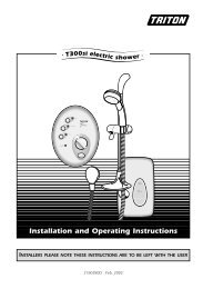
. <strong>T60si</strong> electric shower .Installation and Operating InstructionsINSTALLERS PLEASE NOTE THESE INSTRUCTIONS ARE TO BE LEFT WITH THE USER2180269D Aug 2001
<strong>T60si</strong>CONTENTSPageImportant safety information 1Introduction 2Advice to users 2Key to main components 3Electrical requirements 4 - 5Water requirements 6Siting of the shower 6 - 7Installation – plumbing 8 - 9Installation – electrical 10Replacing the cover 11Fitting the riser rail 12Fitting the hose and sprayhead 13Commissioning 14Operating the shower 15 - 16Operating functions 17Cleaning 18Spare parts 19 - 20Temperature/flow rate graph 21Fault finding 22 - 23Guaranteerear coverTo ensure the product suitability for commercial and multiple installations,please contact <strong>Triton</strong>’s specification advisory service prior to installation.Telephone: (024) 7632 5491Facsimile: (024) 7632 4564E mail: reception@triton.plc.uk
<strong>T60si</strong>PLEASE READ THIS IMPORTANT SAFETY INFORMATION◆ Products manufactured by <strong>Triton</strong> are safe and without risk provided they are installed, used andmaintained in good working order in accordance with our instructions and recommendations.◆ DO NOT operate the unit if frozen, or suspected of being frozen. It must thaw out before using.◆ DO NOT operate the unit if the sprayhead or spray hose becomes damaged.◆ DO NOT restrict flow out of the shower by placing sprayhead in direct contact with your body.◆ DO NOT operate the shower if water ceases to flow during use or if water has entered inside theunit because of an incorrectly fitted cover.◆ WARNING: If re-starting the shower immediately after stopping, be aware that a slug of hotwater will be expelled for the first few seconds.1 GENERAL1.1 Isolate the electrical and water supplies beforeremoving the cover.1.2 Read all of these instructions and retain themfor later use.1.3 DO NOT take risks with plumbing or electricalequipment.1.4 Isolate electrical and water supplies BEFOREproceeding with the installation.1.5 The unit must be mounted onto the finishedwall surface (on top of the tiles). DO NOT tile up tounit after fixing to wall.1.6 Contact Customer Service (see back page), ifany of the following occur;a) If it is intended to operate the shower at pressuresabove the maximum or below the minimum stated.b) If the unit shows a distinct change in performance.c) If the shower is frozen.1.7 If it is intended to operate the shower in areasof hard water (above 200 ppm temporary hardness), ascale inhibitor may have to be fitted. For advice on the<strong>Triton</strong> Scale Inhibitor, contact <strong>Triton</strong> Customer Service.1.8 The sprayplate and cartridge must be cleanedregularly with descalent to remove scale and debris,otherwise restrictions to the flow on the outlet of theunit will result in higher temperatures and could alsocause the Pressure Relief Device in unit to operate.1.9 This product is not suitable for mounting intosteam rooms or steam cubicles.2 PLUMBING2.1 The plumbing installation must comply withWater Regulations, Building Regulations or anyparticular regulations as specified by Local WaterCompany or Water Undertakers and should be inaccordance with BS 6700.2.2 The supply pipe must be flushed to clear debrisbefore connecting to the shower unit.2.3 DO NOT solder pipes or fittings within 300mmof the shower appliance, as heat transfer can damagecomponents.12.4 DO NOT fit any form of outlet flow control asthe outlet acts as a vent for the heater can.2.5 DO NOT use excessive force when makingconnections to the flexible hose or sprayhead, fingertightness is sufficient.2.6 All plumbing connections MUST be completedBEFORE making the electrical connections.3 ELECTRICAL3.1 The installation must comply withBS 7671 ‘Requirements for electrical installations’ (IEEwiring regulations) or any particular regulations asspecified by the local Electrical Supply Company.3.2 This appliance MUST be earthed.3.3 In accordance with ‘The Plugs and Sockets etc.(Safety) Regulations 1994’, this appliance is intendedto be permanently connected to the fixed wiring ofthe electrical mains system.3.4 Ensure all electrical connections are tight toprevent overheating.3.5 Fuses do not give personal protection againstelectric shock.3.6 To enhance electrical safety a 30mA residualcurrent device (RCD) should be installed in all UKelectric and pumped shower circuits. This may be partof the consumer unit or a separate unit.3.7 Switch off immediately at isolating switch ifwater ceases to flow during use.3.8 Other electrical equipment i.e. extractor fans,pumps must not be connected to the circuits withinthe unit.3.9 Switch off at isolating switch when not in use.This is a safety procedure recommended with allelectrical appliances.3.10 As with all electrical appliances it isrecommended to have the shower and installationchecked at least every two years by a competentelectrician to ensure there is no deterioration due toage and usage.
<strong>T60si</strong>INTRODUCTIONThis book contains all the necessary fitting andoperating instructions for your <strong>T60si</strong> electricshower. Please read them carefully.The shower installation must be carried out by asuitably qualified person and in the sequence ofthis instruction book.Care taken during the installation will ensure along, trouble-free life from your shower.SPECIFICATIONSElectricalNominal power Nominal powerrating at 240Vrating at 230V8 kW – (40A MCB rating) 7.4 kW – (40A MCB rating)7 kW – (30A MCB rating) 6.5 kW – (30A MCB rating)WaterInlet connection – 15mm diameter.Outlet connection – 1/2” BSP male thread.Entry PointsWater – top, bottom and backCable – top, bottom and back.MaterialsBackplate, cover, controls, sprayhead – ABS.Sprayplate – Acetal.Elements – Minerally insulated corrosion resistantmetal sheathing.DimensionsHeight - 255 mmWidth - 182 mmDepth - 96 mmStandards and ApprovalsSplashproof rating IPX4.Complies with the requirements of current Britishand European safety standards for household andsimilar electrical appliances.Complies with requirements of the BritishElectrotechnical Approvals Board (BEAB).Meets with Compliance with EuropeanCommunity Directives (CE).ADVICE TO USERSThe following points will help you understandhow the shower operates:A The electric heating elements operate at aconstant rate at your chosen power setting. It isthe flow rate of the water passing through theheater unit which determines the showertemperature at any given setting. (The slower theflow the hotter the water becomes, and the fasterthe flow the cooler the water).B During Winter the mains water supply will becooler than in the Summer. Therefore thetemperature of the shower will vary betweenseasons on any one setting of the temperaturecontrol, e.g. if you have chosen setting number 6as your preferred shower temperature in theSummer, you may have to increase that numberduring Winter by adjusting the temperaturecontrol anti-clockwise (which in effect slows thewater flow).C The stabiliser valve minimises variations inshower temperature during mains water pressurechanges. If changes in shower temperature areexperienced during normal use, it will most likelybe caused by the water pressure falling near to orbelow the minimum level. The drop in pressuremay be due to water being drawn off at otherpoints in the house whilst the shower is in use. Ifpressure drops appreciably below the minimum,the heating elements will automatically cut out.If ever the water becomes too hot and youcannot obtain cooler water, first check thatthe sprayplate in the sprayhead has notbecome blocked.DO NOT place items such as soap or shampoobottles on top of the unit. Liquid could seepthrough the joint between the cover andbackplate, and possibly damage the sealingrubber.Replacement parts can be ordered from <strong>Triton</strong>Customer Service. See 'spare parts' for detailsand part numbers.Due to continuous improvement and updating,specification may be altered without prior notice.2
<strong>T60si</strong>KEY TO MAIN COMPONENTS(inside unit - fig.1)1Fig.11 Top pipe/cable entry2 Bottom pipe/cable entry104 453 Area for rear pipe and68cable entry124 Cover screw fixings5 Wall screw fixings6 Terminal block7255mm7 Pressure switch cartridge118 Power selector assembly9 Stabilising valve14910 Earth connection11 Can and element assembly13512 Thermal cut-out (main)13 Cable clamp53mm1543241mm14 Pressure relief device (PRD)15 Thermal cut-out (outlet)26mm16182 mm40 mm16 Shower outletPack contentsShower unitSprayheadRiser rail kit and fittingsFlexible hoseScrew fixing kitInstructions, guarantee, etc.3
<strong>T60si</strong>ELECTRICAL REQUIREMENTSRCD(can be part ofconsumer unit)Fuse ormcbWARNINGTHIS APPLIANCE MUST BE EARTHEDThe installation, supply cable and circuitprotection must conform with IEE wiringregulations and be sufficient for theamperage required.The following notes are for guidance only:1 The shower must only be connected to a230-240V ac supply. If you are installing a showerwith a kilowatt rating above 9kW, it is advisableto contact the local electricity supply company.1.1 The electrical rating of the shower is shownon the rating label (fig.2) within the unit.80A or 100Amain switchConsumerunitMetertailsPull cordisolating switchFig.2MeterShowerunitFig.3 schematic of installation circuitIncomingsupplyfuse2 Before making any sort of electricalconnection within the installation, ensure that noterminal is live. If in any doubt, switch off thewhole installation at the consumer unit.3 The shower must be connected to its ownindependent electrical circuit. IT MUST NOT beconnected to a ring main, spur, socket outlet,lighting circuit or cooker circuit.3.1 The electrical supply must be adequate forthe loading of the unit and existing circuits.4 Check your consumer unit (main fuse box)has a main switch rating of 80A or above and thatit has a spare fuse way which will take the fuse ormcb necessary for the shower (fig.3).4.1 If your consumer unit has a rating below80A or if there is no spare fuse way, then theinstallation will not be straight forward and mayrequire a new consumer unit serving the house orjust the shower.4.2 You will need to contact the local electricitycompany. They will check the circuit and carry outwhat is necessary. They will also check the mainbonding.5 The earth continuity conductor of theelectrical installation must be effectivelyconnected electrically to all exposed metal parts ofother appliances and services in the room inwhich the shower is to be installed, to conform tocurrent IEE regulations.Table ACIRCUIT PROTECTIONunitcartridgerating mcb fuse7.0kW 30/32A 30A7.5kW 32A 35A8.0kW 40A 35A8.5kW 40A 45A9.0kW 40A 45A9.5kW 40/45A 45A10.5kW 45A 45A4
<strong>T60si</strong>ELECTRICAL REQUIREMENTS5.1 All exposed metallic parts in the bathroommust be bonded together using a cable of at least4mm 2 cross sectional area. These parts includemetal baths, radiators, water pipes, taps andwaste fittings.6 For close circuit protection DO NOT use arewireable fuse. Instead use a suitably ratedminiature circuit breaker (MCB) or cartridge fuse(see table A).6.1 In the interest of electrical safety a 30mAresidual current device (RCD) should be installedin all UK electric and pumped shower circuits. Thismay be part of the consumer unit or a separateunit.7 A 45 amp double pole isolating switch witha minimum contact gap of 3mm in both polesmust be incorporated in the circuit.7.1 It must have a mechanical indicatorshowing when the switch is in the OFF position,and the wiring must be connected to the switchwithout the use of a plug or socket outlet.7.2 The switch must be accessible and clearlyidentifiable, but out of reach of a person using afixed bath or shower, except for the cord of acord operated switch, and should be placed soTable BTwin and earth PVC insulated cableCURRENT CARRYING CAPACITYclipped direct orinstalled in an in conduit buried in a noninsulated wall or trunking insulated wall6mm 2 6mm 2 6mm 232A 38A 46A10mm 2 10mm 2 10mm 243A 52A 63Athat it is not possible to touch the switch bodywhile standing in a bath or shower cubicle. Itshould be readily accessible to switch off afterusing the shower.8 Where shower cubicles are located in anyrooms other than bathrooms, all socket outlets inthose rooms must be protected by a 30mA RCD.9 The current carrying capacity of the cablemust be at least that of the shower circuitprotection (see table B).9.1 To obtain full advantage of the powerprovided by the shower, use the shortest cableroute possible from the consumer unit to theshower.9.2 It is also necessary to satisfy thedisconnection time and thermal constraints whichmean that for any given combination of currentdemand, voltage drop and cable size, there is amaximum permissible circuit length.10 The shower circuit should be separated fromother circuits by at least twice the diameter of thecable or conduit.10.1 The current rating will be reduced if thecabling is bunched with others, surrounded bythermal loft or wall insulation or placed in areaswhere the ambient temperature is above 30°C.Under these conditions, de-rating factors applyand it is necessary to select a larger cable size.10.2 In the majority of installations, the cablewill unavoidably be placed in one or more ofthe above conditions. This being so, it isstrongly recommended to use a minimum of10mm cabling throughout the showerinstallation.10.3 In any event, it is essential that individualsite conditions are assessed by a competentelectrician in order to determine correct cable sizeand permissible circuit length.16mm 2 16mm 2 16mm 257A 69A 85ANote: Cable selection is dependenton de-rating factors5
<strong>T60si</strong>IsolatingstopvalveMainswatersupplyMains electric supply (via double pole switch)ShowerunitDoublepoleisolatingswitchSeparate permanentlyconnected supplyfrom consumer unitFig.4Diagrammatic view (not to scale)WATER REQUIREMENTSThe installation must be in accordance with WaterRegulations/Byelaws.To ensure activation of the heating elements, theshower must be connected to a mains watersupply with a minimum running pressure of100 kPa (1.0 bar) at a minimum flow rate of eightlitres per minute and a maximum static pressureof 1,000 kPa (10 bar).NOTE: If the stated flow rates are not available, itmay not be possible to achieve optimumperformance from the unit throughout the year.During periods of high ambient temperatures itmay be necessary to select a low power setting toachieve your preferred shower temperature.The water supply can be taken from a cold waterstorage cistern provided there is a minimum headof ten metres above the sprayhead. It must be anindependent supply to the shower only.If it is intended to operate the shower at pressuresabove the maximum or below the minimumstated, contact Customer Service for advice.Fig.4 shows a typical system layout.Do not use jointing compounds on any pipefittings for the installation.SITING OF THE SHOWERWARNING: The shower must not bepositioned where it will be subjected tofreezing conditions.FOR EASE OF SERVICING, THE UNIT MUSTALWAYS BE MOUNTED ON THE SURFACE OFTILED WALLS. NEVER TILE UP TO THE UNIT.Refer to figure 5 for correct siting of shower.Position the unit where it will NOT be in directcontact with water from the sprayhead. Positionthe shower unit vertically.Allow sufficient room between the ceiling and theshower to access the cover top screws.NOTE: Water regulations require the sprayhead be‘constrained by a fixed or sliding attachment sothat it can only discharge water at a point not lessthan 25mm above the spill-over level of therelevant bath, shower tray or other fixedappliance’. The use of the supplied retaining ringwill in most cases meet this requirement, but ifthe sprayhead can be placed within a bath, basin6
<strong>T60si</strong>or shower tray, then a double check valve, orsimilar, must be fitted in the supply pipework toprevent back-flow.Pressure relief safety deviceA pressure relief device (PRD) is designed into theshower unit which complies with Europeanstandards. The PRD provides a level of applianceprotection should an excessive build up ofpressure occur within the shower.DO NOT operate the shower with a damaged orkinked shower hose, or a blocked sprayheadwhich can cause the PRD to operate.When commissioning, the sprayhead must beremoved from the flexible hose, while at the sametime the temperature control must be at theminimum flow position. Failure to follow thisprocedure may also cause the PRD to operate.Ensure the shower is positioned over a bath orshower tray because if the PRD operates, thenwater will eject from the bottom of the unit.Should this happen, turn off the electricity andwater supplies to the shower at the isolatingswitch and stopvalve. Contact Customer Servicefor advice on replacing the PRD.RetainingringShower unit canbe mounted eitherside of riser rail25mm minimumOutline of bathor shower trayMains cold watersupply (bottom,top or back)Height ofsprayheadand showerto suit user'srequirementShower unitmust not bewithin an area1 metre from baseFig.5Diagrammatic view (not to scale)7
<strong>T60si</strong>Fig. 6Fig. 7Fig. 8Fig. 9120 mmINSTALLATION – plumbingPlumbing to precede wiring.Unscrew the two top and one bottom retainingscrews (fig.6) and lift the cover from thebackplate.For ease of installation, all pipe work and electricalwiring should be positioned in place, ready forfinal connection, before fitting the backplate unitto the wall.Use the backplate as a template and mark outlineon the wall so that pipework can be cut to suit.Three entry positions – top, bottom or back, areavailable for the pipework and cable.NOTE: Deviations from the designated entrypoints will invalidate product approvals.Fit a finishing trim in either the top or bottom ofthe backplate (fig.7) depending upon whethertop or bottom entry has been chosen.If installing a feed pipe from the top, as a guidefor cutting the pipe, the centres are 120mm(fig.8).Where pipework enters from the back or bottom,note the centre of the inlet valve to the wallsurface is 20mm (fig.9).Having decided the entry positions, cable andpipework must be installed prior to fixing thebackplate to the wall.WARNING: The outlet of the shower acts as avent and must not be connected to anythingother than the hose and sprayhead supplied.DO NOT use jointing compounds on any pipefittings for the installation.DO NOT use soldered fittings within the vicinity ofthe shower unit.NOTE: An additional stopvalve (complying withWater Regulations) must be fitted in the mainswater supply to the shower as an independentmeans of isolating the water supply shouldmaintenance or servicing be necessary.Turn off water supply either at the mainsstopvalve or the isolating stopvalve.15mm copper or stainless steel pipe may be beused and all pipework and fittings can be fixedand tightened except the final joint to the showerinlet.20 mm8
<strong>T60si</strong>A 15mm x 15mm straight coupler or elbow fitting(fig.10) must be used for connection to theshower inlet. NOTE: The shower inlet connectionis designed to enter a compression fitting only.DO NOT use push fit connectors as fullengagement cannot be guaranteed.Ensure the plastic filter (fig.11) is inserted in thesupply pipe before connection. This helps toprevent ingress of debris.If entry is from the rear, the conex nut fitting willbe partially behind the surface of the wall (fig.9).This area must be left clear when plastering overthe pipework in order to make the nut accessiblefor future adjustments.DO NOT use excessive force when making theseconnections.When all pipework is complete, temporarily placethe backplate unit onto the pipework and markholes on the wall for the fixing screws (fig.12).Remove the backplate and drill and plug the holesto suit fixing screws supplied. (The wallplugsprovided are suitable for most brick walls – use anappropriate masonry drill, but if the wall isplasterboard or a soft building block, you mustuse special wallplugs and an appropriate drill bitobtainable from most hardware stores).Important: Before completing the connection ofthe water supply to the inlet of the shower, and incompliance with Water Regulations, flush out thepipework to remove all swarf and system debris.This can be achieved by connecting a hose to thepipework and turning on the mains water supplylong enough to clear the debris to waste.After flushing out, turn off the mains watersupply, re-position the unit onto the pipeworkand tighten final connection at shower inlet.Turn on the water supply and check for watertightness.Position the backplate onto the wall and screwthe top and bottom fixing screws into position.Ensure the unit is square on the wall and tightenthe two fixing screws.FilterElbow orStraightcouplerFig.10Fig.11Fig.129
<strong>T60si</strong>Fig.13653EN14L2INSTALLATION – electricalSWITCH OFF THE ELECTRICITY SUPPLY.Figure 13 shows a schematic wiring diagram.The cable entry points are shown in figure 1.The cable can be surface clipped, hidden or via20mm conduit.NOTE: Conduit entry can only be from rear. Routethe cable into the shower unit and connect to theterminal block (fig.14) as follows:-Earth cable to terminal marked ENeutral cable to terminal marked N7Live cable to terminal marked L1 Terminal block2 Thermal cut-out (main)3 Neon indicator4 MicroswitchesFig.14ELN5 Element6 Element7 Thermal cut-out (outlet)<strong>T60si</strong>TerminalblockIMPORTANT: Fully tighten the terminal blockscrews and ensure that no cable insulation istrapped under the screws. Loose connectionscan result in cable overheatingNOTE: The supply cable earth conductor must besleeved. The outer sheath of the supply cablemust be stripped back to the minimum allowingsufficient to be held at the clamp (fig.14). Thecable clamp is suitable for 6 mm 2 cable, or can bereversed for use with 10 mm 2 cable.If a cable larger than 10 mm 2 is used, DO NOT usethe cable clamp. Instead, the cable must besecured either by routing through conduit or intrunking or by embedding in the wall, inaccordance with IEE regulations.The use of connections within the unit, or otherpoints in the shower circuit, to supply power toother equipment i.e. extractor fans, pumps etc.will invalidate the guarantee.DO NOT switch on the electricity supply untilthe cover has been fitted.CableclampNOTE: The elements on UK models are to240V specification and will give a lower kWrating if the voltage supply is below 240V.10
<strong>T60si</strong>REPLACING THE COVERThe power selector spindle must be aligned asshown (fig.15).To ensure that the temperature control is correctlypositioned on the stabilising valve, temporarilyplace the cover in position so that the splinesengage and rotate the temperature control fullyclockwise until a ‘stop’ is felt. The valve is now inthe closed position.Remove the cover and position the temperaturecontrol so that it points towards the ‘STOP’position (fig.16).Position the power selector on the cover to the'ECONOMY' position (fig.17).Replace the cover squarely to the backplate andguide into position so that the knobs locatecorrectly into the splined spindles. Should anydifficulty arise, re-check the points above.Secure the cover in position with the threeretaining screws.DO NOT switch on the electricity supply to theshower until the commissioning has been carriedout.SelectorspindleFig.15Fig.16Fig.1711
<strong>T60si</strong>Fig.18ThumbscrewSaddleHolderWARNING: Check there are no hidden cablesor pipes before drilling holes for wall plugs.Use great care when using power tools nearwater. The use of a residual current device(RCD) is recommended.Fig.19RailBracket inlower positionFig.20Bracket inupper positionFinishingcapHoseretainingringFinishingcapFITTING THE RISER RAILDecide the position for the rail on the wall withinthe shower area.Fitting the sprayhead holder to riser rail.Holding the sprayhead holder (fig.18), align thesaddle with the riser rail (fig.18) and push the railthrough the aperture. Tighten the thumbscrew(fig.18) to locate the holder on the rail.Fitting the wall mounting brackets.Drill and plug wall for mounting a bracket in alower position only. (The wallplugs provided aresuitable for most brick walls – use an appropriatemasonry drill, but if the wall is plasterboard or asoft building block, you must use special wallplugsand an appropriate drill bit obtainable from mosthardware stores).Screw the bracket (fig.19) to the wall.Locate the riser rail in the lower mountingbracket.Place the other mounting bracket (fig.20) on topof the rail, and mark the fixing hole on the wall.Ensure the hole position is vertically aligned.Remove the bracket and rail. Drill and plug thewall.At this stage, slide the hose retainer – smallerdiameter onto the rail (fig.21) below the holder.Replace the rail into the lower bracket. Replacethe upper bracket (fig.20) on top of rail andscrew the bracket to the wall.When fitting the metal riser rail, position it so thatthe indent is facing the wall and is firmly engagedin the upper bracket slot.Slide the finishing caps (fig.22) on both the upperand lower mounting brackets.Fig.21Fig.2212
<strong>T60si</strong>FITTING THE HOSE AND SPRAYHEADFeed the flexible hose through the hose retainer(fig.23), in order that it acts as a retaining ring –Water Regulations.Screw the flexible hose to the shower outlet andsprayhead (fig.24) ensuring the supplied washersare in place at both ends of the flexible hose.Place the sprayhead into the holder (fig.25) andcheck that it fits correctly. NOTE: The holder isslightly tapered and the sprayhead will only fitfrom one direction.Important: It is the conical end of the hose whichgrips into the holder. The sprayhead will not fit inthe holder without the hose attached.However at this stage, disconnect the sprayheadand lay aside until the shower unit has beencommissioned.ShowerSprayheadFig.23Fig.24WashersHolderSprayheadFig.2513
<strong>T60si</strong>Fig.26Fig.27COMMISSIONINGThe first operation of the shower is intended toflush out any unit debris and to ensure the heaterunit contains water before the elements areswitched on. The electricity must be switched OFFat the isolating switch. The flexible hose must bescrewed to the shower outlet but without thesprayhead attached to the hose. Ensure the outletof the hose is directed to waste.Ensure the water supply is turned OFF at theisolating stopvalve.Rotate the temperature control fully anticlockwiseto ‘10’, the minimum flow position(fig.26). NOTE: Leaving the control at anyposition other than ‘10’ may cause the PRD tooperate.Turn the water supply back ON at the isolatingstopvalve.Wait until water starts to flow from the flexiblehose then rotate the temperature controlclockwise to ‘1’, the maximum flow position(fig.27).It will take approximately thirty seconds for asmooth flow of water to be obtained whilst airand any debris is being dispersed from theshower. When a smooth flow of water isobtained, rotate the temperature control from ‘1’to ‘10’ and back again several times to release anytrapped air within the unit.Once the flushing out has been completed, stopthe water flow by rotating the temperaturecontrol fully clockwise to the 'STOP' position.Fit the sprayhead to the flexible hose and place inthe holder.Switch on the electricity supply to the shower atthe isolating switch.The shower is now ready for normal operation.NOTE: IN NORMAL USE, IT IS IN ORDER TOLEAVE THE WATER SUPPLY PERMANENTLYON TO THE SHOWER UNIT, BUT AS WITHMOST ELECTRICAL APPLIANCES, THE UNITMUST BE SWITCHED OFF AT THEISOLATING SWITCH WHEN NOT IN USE.14
<strong>T60si</strong>OPERATING THE SHOWERNOTE: Ensure the commissioning procedure hasbeen carried out.The flow of water is controlled by the combinedstart/stop temperature control. To obtain warmwater turn the control slowly anti-clockwise to themid position (fig.28).If the water is too hot, turn the temperaturecontrol slowly clockwise towards the low numbers(fig.29).If the water is too cool, turn the temperaturecontrol slowly anti-clockwise towards the highnumbers (fig.30).To stop the showerTurn the temperature control fully clockwise tothe ‘STOP’ position, and water will cease to flow.WARNING: If re-starting immediately afterstopping, be aware that a slug of hot water willbe expelled for the first few seconds.Fig.28Fig.29Fig.3015
<strong>T60si</strong>Fig.31PowerselectorEconomyHighTemperaturecontrolPower selectorThe power selector (fig.31) has two positions –economy and high.Single red symbol is an economy setting for usingless power during warmer months when theambient water temperature is high.NOTE: If the stated flow rate required for the unitcannot be met due to low water pressure, it willbe necessary to operate the unit on this settingduring the warmer months because of flow ratelimitations entering the unit.Double red symbol is a high setting which allowsthe highest flow achievable for your preferredtemperature. This setting should be regarded asnormal for optimum shower performancethroughout the year.WARNING: After any servicing of the mainswater supply, always start the unit with theelectricity OFF at the isolating switch and thenrotate the temperature control fully anti-clockwisein order to purge any air in the pipework.NOTE: It is advisable to be certain that theshowering temperature is satisfactory by testingwith your hand before stepping under thesprayhead. There will always be a time delay often to fifteen seconds between selecting a flowrate and the water reaching the stabletemperature for that flow rate.CAUTION: It is recommended that persons whomay have difficulty understanding or operatingthe shower controls should not be left unattendedwhilst showering. Special consideration should begiven to young children and the less able bodied.16
<strong>T60si</strong>OPERATING FUNCTIONSPower indicatorThe power neon (fig.32) will light when thetemperature control is turned to the ‘start’position indicating that power is on to the heatingelements. It will remain lit at all positions between‘1’ and ‘10’, but will extinguish when the controlis turned back to the ‘stop’ position. Notehowever, that the neon will extinguish duringnormal showering if the low water pressure cutoutoperates.Low water pressure cut-outIf the water pressure falls below the minimumrequired for correct operation of the shower,power will be switched off to the heatingelements preventing any maintained temperaturerises (water will continue to flow).Power will automatically be restored whenadequate water pressure returns.Temperature limiterDuring normal operation if an overheattemperature is sensed, power to the elements willbe reduced. Water will continue to flow. Whenthe temperature has cooled sufficiently, power tothe elements will be automatically restored to theprevious setting at the time of interruption.Safety cut-outThe unit is fitted with a thermal cut-out safetydevice. In the event of abnormal operation whichcould cause unsafe temperatures within the unit,the device will disconnect the heating elements. Itwill require a visit from a qualified engineer todetermine the nature of the fault and replace thesafety device, once the unit has been repaired.Fig.32Powerneonindicator17
<strong>T60si</strong>Fig.33'O' ringSprayheadSprayplateCLEANINGDo not use abrasive or solvent cleaningfluids. The shower unit, riser rail, hose, etc.should be cleaned using a soft cloth andwarm water.It is advised before cleaning, to turn the isolationswitch off, thus avoiding the shower beingaccidentally switched on.IT IS IMPORTANT TO KEEP THE SPRAYHEADCLEAN TO MAINTAIN THE PERFORMANCE OF THESHOWER. The hardness of the water willdetermine the frequency of cleaning. For example,if the shower is used every day in a very hardwater area, it may be necessary to clean thesprayhead on a weekly basis.BezelSprayplate removalRemove the sprayhead from the hose. Unscrewthe bezel and remove the sprayplate completewith ‘O’ ring from the sprayhead (fig.33).Clean the sprayplate with a suitable brush orpreferably leave to soak overnight in a mildproprietary descalent. Ensure all traces of scale areremoved and thoroughly rinse in clean waterafterwards.Carefully replace the ‘O’ ring onto the sprayplateand replace the sprayplate into the sprayhead.Secure by screwing on the bezel.Before replacing the sprayhead on the hose, it isadvisable to direct the hose to waste, switch OFFthe electricity supply at the isolating switch andturn the temperature control to ‘1’.This operation will flush out any loose scaledeposits in the unit. Stop after approximatelythirty seconds and replace the sprayhead.Turn on the electricity supply.18
<strong>T60si</strong>SPARE PARTSRef DescriptionPart No.1 Riser rail set 833018902 Sprayhead holder 842000102143 Flexible hose 220011604 Sprayhead assembly 2200460055 Hose retainer 70522516 Cover assembly 813002503619
<strong>T60si</strong>SPARE PARTSRef DescriptionPart No.710117 Terminal block 822000708 Thermal cut-out (main) 2200987089 Heater can assembly7 kW 833059608 kW 83305970149121310 Power neon 2200509011 Selector switch assembly 8250005012 Cartridge assembly 8240021013 Stabiliser valve assembly 8260075014 PRD 8330133015 Outlet pipe assembly 85000170- Switch and wire kit 8330598015- Filter 7052161- Microswitch 2200891020
<strong>T60si</strong>Temperature / flow rate graph (0° C ambient)60408kW7kW20010.610.29.89.498.68.27.87.476.66.25.85.454.64.23.83.432.62.21.81.410.621
<strong>T60si</strong>FAULT FINDINGIMPORTANT: Switch OFF the electricity at the mains supply and remove the circuit fuse beforeremoving the cover from the shower while attempting any fault finding inside the unit.Problem/Symptom Cause Action/cure1 Showerinoperable, no waterflow.2 Water too hot.3 Watertemperature cyclinghot/cool or hot/coldat intervals.4 Water too cool orcold.1.1 No mains watersupply to shower.1.2 Unit malfunction.2.1 Not enough waterflowing through theshower.2.2 Blockage in supply.2.3 Increase in ambientwater temperature.3.1 Heater cycling ontemperature limiter cutouts.4.1 Too much flow.4.2 Water pressure belowminimum required (seerating label).4.3 Reduction in ambientwater temperature.4.4 Interrupted powersupply.4.5 Safety cut-outoperated.1.1.1 Check if isolating valves are fully open.Check if a blockage in inlet filter or in pipework.1.2.1 Have unit checked. Ring Customer Service.2.1.1 Increase flow rate via temperature control.2.1.2 Blocked sprayhead - clean or replaceblocked sprayplate in sprayhead.2.2.1 Check if stop valves are fully open. Check ifa blockage in inlet filter.2.3.1 Re-adjust flow rate to give increased flow.2.3.2 Select ‘economy’ power.3.1.1 See 'Water too hot' causes 2.1, 2.2 and 2.3and their appropriate action/cures. If it continues,contact <strong>Triton</strong> Customer Service.4.1.1 Reduce flow rate via temperature control.4.2.1 Is water supply mains or tank fed ?4.2.2 If tank fed, re-plumb to mains water supplyor see 4.2.4.4.2.3 If mains fed, ensure that mains stopvalve isfully open and that there are no other restrictionsin the supply while shower is in use, or see 4.2.4.4.2.4 Fit pump to give minimum pressure (seerating label). Contact Customer Service for advice.4.3.1 Re-adjust flow rate to give reduced flow.4.3.2 Select ‘high’ power.4.4.1 Blown fuse or circuit breaker. Check supply.Renew or reset fuse or circuit breaker. If it failsagain, consult a qualified electrician.4.4.2 Power cut. Check other appliances and ifnecessary, contact local Electricity Supply Co.4.5.1 The thermal safety cut-out device hasoperated. Have the unit checked by suitablyqualified electrician or contact Customer Service.22
<strong>T60si</strong>FAULT FINDING (continued)Problem/Symptom Cause Action/cure5 Shower variesfrom normaltemperature to coldduring use.6 Pressure reliefdevice has operated(water ejected fromPRD tube).5.1 Water pressure hasdropped below minimumrequired.6.1 Blocked sprayhead.6.2 Twisted/blockedflexible shower hose.6.3 Sprayhead notremoved whilstcommissioning.5.1.1 Wait until the water pressure resumes tonormal.6.1.1 Clean or replace blocked sprayplate insprayhead and then fit new PRD.6.2.1 Check for free passage through hose.Replace the hose if necessary and fit new PRD.6.3.1 Fit new PRD. Commission unit withsprayhead removed.Note: Identify cause of operation before fitting new PRD unit.When fitting a new PRD, follow the commissioning procedure.It is advised all electrical maintenance/repairs to the showershould be carried out by a suitably qualified person.23
<strong>T60si</strong>24
UKASQUALITYMANAGEMENT003
T RITON S TANDARD G UARANTEE<strong>Triton</strong> Plc guarantee this product against allmechanical and electrical defects arising from faultyworkmanship or materials for a period of two yearsfor domestic use only, from the date of purchase,provided that it has been installed by a competentperson in full accordance with the fittinginstructions.Any part found to be defective during thisguarantee period we undertake to repair or replaceat our option without charge so long as it has beenproperly maintained and operated in accordancewith the operating instructions, and has not beensubject to misuse or damage.This product must not be taken apart, modified orrepaired except by a person authorised by <strong>Triton</strong>Plc. This guarantee applies only to products installedwithin the United Kingdom and does not apply toproducts used commercially.This guarantee does not affect your statutory rights.What is not covered:1 Breakdown due to: a) use other than domesticuse; b) wilful act or neglect; c) any malfunctionresulting from the incorrect use or quality ofelectricity, gas or water or incorrect setting ofcontrols; d) faulty installation.2 Repair costs for damage caused by foreign objectsor substances.3 Call out charges where no fault has been foundwith the appliance.4 The cost of repair or replacement of pressurerelief devices, sprayheads, hoses, riser rails and/orwall brackets, isolating switches, electrical cable,fuses and/or circuit breakers or any otheraccessories installed at the same time as these donot form the mechanical and electrical componentscontained within the unit..5 The cost of routine maintenance, adjustments,overhaul modifications or loss or damage arisingtherefrom, including the cost of repairing damage,breakdown, malfunction caused by corrosion,furring, pipe scaling, lime scale, system debris orfrost.Service PolicyIn the event of a complaint occurring, the followingprocedure should be followed:1 Telephone Customer Service on (024) 7637 2222(08457 626591 in Scotland and in Northern Ireland),having available the model number and power ratingof the product, together with the date of purchase.2 <strong>Triton</strong> Customer Service will be able to confirmwhether the fault can be rectified by either theprovision of a replacement part or a site visit from aqualified <strong>Triton</strong> service engineer.3 If a service call is required it will be booked and thedate of call confirmed. In order to expedite yourrequest, please have your postcode available whenbooking a service call.4 It is essential that you or an appointedrepresentative (who must be a person of 18 years ofage or more) is present during the service engineer'svisit and receipt of purchase is shown.5 A charge will be made in the event of an abortedservice call by you but not by us, or where a callunder the terms of guarantee has been booked andthe failure is not product related (i.e. scaling andfurring, incorrect water pressure, pressure reliefdevice operation, electrical installation faults).6 If the product is no longer covered by theguarantee, a charge will be made for the site visit andfor any parts supplied.7 Service charges are based on the account beingsettled when work is complete, the engineer will thenrequest payment for the invoice. If this is not made tothe service engineer or settled within 10 workingdays, a £10 administration charge will be added.Replacement Parts PolicyAvailability: It is the policy of <strong>Triton</strong> to maintainavailability of parts for the current range of productsfor supply after the guarantee has expired. Stocks ofspare parts will be maintained for the duration of theproduct’s manufacture and for a period of five yearsthereafter.In the event of a spare part not being available asubstitute part will be supplied.Payment: The following payment methods can beused to obtain spare parts:1 By post, pre-payment of pro forma invoice bycheque or money order.2 By telephone, quoting credit card (MasterCard orVisa) details.3 By website order, www.tritonshowers.co.uk<strong>Triton</strong> Plc, Shepperton Park, Caldwell Road,Nuneaton, Warwickshire. CV11 4NRCustomer Service☎ (024) 7637 2222Scottish and Northern IrelandCustomer Service☎ 08457 626591Trade Installer Hotline☎ (024) 7632 5491Fax: (024) 7632 4564www.tritonshowers.co.ukE mail: reception@triton.plc.uk