The MP-Series of Hydraulic Pressure Intensifiers
The MP-Series of Hydraulic Pressure Intensifiers
The MP-Series of Hydraulic Pressure Intensifiers

You also want an ePaper? Increase the reach of your titles
YUMPU automatically turns print PDFs into web optimized ePapers that Google loves.
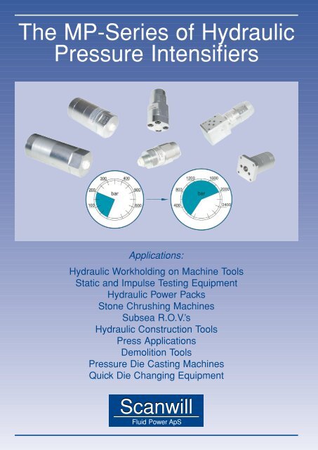
<strong>The</strong> <strong>MP</strong>-<strong>Series</strong> <strong>of</strong> <strong>Hydraulic</strong><br />
<strong>Pressure</strong> <strong>Intensifiers</strong><br />
Applications:<br />
<strong>Hydraulic</strong> Workholding on Machine Tools<br />
Static and Impulse Testing Equipment<br />
<strong>Hydraulic</strong> Power Packs<br />
Stone Chrushing Machines<br />
Subsea R.O.V.’s<br />
<strong>Hydraulic</strong> Construction Tools<br />
Press Applications<br />
Demolition Tools<br />
<strong>Pressure</strong> Die Casting Machines<br />
Quick Die Changing Equipment<br />
Scanwill<br />
Fluid Power ApS
Scanwill<br />
Fluid Pow er ApS<br />
Function:<br />
<strong>The</strong> <strong>MP</strong>-<strong>Series</strong> <strong>of</strong> hydraulic pressure intensifi ers are<br />
reciprocating, and will automatically increase a supplied<br />
pressure to a higher end pressure. Fig. 1 shows<br />
the basic principle <strong>of</strong> the intensifi ers, consisting <strong>of</strong> a<br />
piston arrangement and a Piston Control Valve, PCV.<br />
<strong>The</strong> position <strong>of</strong> the pistons will at the end <strong>of</strong> every stroke<br />
prompt a signal S to the PCV, which makes this change<br />
position, ensuring the pistons are moving in the opposite<br />
direction. This cycle will continue until the end pressure<br />
has been reached. At this point the pistons stop, and will<br />
now only move to maintain the end pressure.<br />
Fig. 1:<br />
<strong>The</strong> Cycle:<br />
When a hydraulic fl uid is supplied to the P-connection <strong>of</strong><br />
the intensifi er and the T-connection is connected to tank,<br />
the oil will be directed through the check valves CV1 and<br />
CV2 to the high pressure connection HP. If the internal<br />
pilot operated check valve POV is incorporated the oil will<br />
go straight to the HP connection. In this situation all the<br />
fl ow supplied goes to the high pres su re side ensuring a<br />
fast fi lling <strong>of</strong> the system. When pump pressure has been<br />
reached, the intensifi er pistons will deliver the fl ow to the<br />
high pressure side, and continue to do so until the required<br />
end pressure has been reached. <strong>The</strong> pistons then stop,<br />
and will only move to make up for a pressure loss due to<br />
leakage or consumption.<br />
A general fl ow curve showing how the intensifi er works is<br />
shown in Fig.2. For evacuating the high pressure side the<br />
internal POV is used. This valve is opened by directing the<br />
supplied pressure to the T-port and connecting the P-port<br />
to tank. This allows the oil from the high pressure side to<br />
fl ow directly back to tank.<br />
Fig. 2:<br />
General Data:<br />
Material:<br />
Surface coating:<br />
Temperature range:<br />
Fluids:<br />
Body parts <strong>of</strong> cast iron or steel, pistons and valves <strong>of</strong> steel<br />
Zinc-Chrome silver blue fi nish<br />
-40° C to +120° C<br />
Recognised hydraulic fl uids and water glycol only.<br />
For other fl uids contact factory or distriutor.<br />
Filtration: 10 micron nominal, maximum 19/16 according to ISO 4406<br />
3
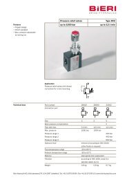
<strong>The</strong> <strong>MP</strong>-T <strong>The</strong> <strong>MP</strong>-T<br />
<strong>Pressure</strong> In ten si fi er<br />
<strong>The</strong> <strong>MP</strong>-T is an in-line pressure intensifi er designed to be positioned in a<br />
low pressure hydraulic system, and will provide higher pressure exactly<br />
where needed (max. 800 bar). Having all the required high pressure valves<br />
incorporated, the need for additional high pressure components is minimized<br />
ensuring a cost effective system. Control <strong>of</strong> the high pressure side is achieved<br />
by valves on the low pressure side through the intensifi er which adds to safety.<br />
<strong>The</strong> intensifi ers are <strong>of</strong>fered with 7 different intensifi cation ratios as standard<br />
with additional ratios on request to meet most intensifi cation requirements. <strong>The</strong><br />
compact design ensures easy installation in new as well as existing hydraulic<br />
circuits.<br />
<strong>The</strong> standard <strong>MP</strong>-T will provide pressure<br />
intensifi cation as required. As an<br />
option a built in pilot operated check<br />
valve, POV, allows the high pressure<br />
side to be relieved through the intensifi<br />
er (see page 3).<br />
Flow & <strong>Pressure</strong>:<br />
Dimensions in mm<br />
<strong>The</strong> supplied fl ow and pressure to the <strong>MP</strong>-T are dependant on the intensifi cation ratio chosen. <strong>The</strong> table shows the fl ow<br />
and pressure for each model. Flow Q1 is when the pump pressure has been reached, and fl ow Q2 is moving up the vertical<br />
part <strong>of</strong> the curve (see graph on page 2). Please note fl ow values will vary with the viscosity <strong>of</strong> the fl uid. Inlet values<br />
must not be exceeded.<br />
Ratio (i)<br />
Inlet Flow<br />
(LPM / GPM)<br />
Outlet Flow Q1<br />
(LPM / GPM)<br />
Outlet Flow Q2<br />
(LPM / GPM)<br />
Inlet <strong>Pressure</strong><br />
(Bar / Psi)<br />
Outlet <strong>Pressure</strong><br />
(Bar / Psi)<br />
1.5<br />
8.0<br />
/ 2. 1 0.8<br />
/ 0.21<br />
0.3<br />
/ 0.08<br />
200<br />
/ 2,900<br />
300 / 4,350<br />
2.0<br />
8.0<br />
/ 2. 1 0.8<br />
/ 0.21<br />
0.2<br />
/ 0.08<br />
200<br />
/ 2,900<br />
400 / 5,800<br />
3.4<br />
15.0<br />
/ 4. 0 2.2<br />
/ 0.58<br />
0.5<br />
/ 0.13<br />
200<br />
/ 2,900<br />
680 / 9,860<br />
4.0<br />
14.0<br />
/ 3. 7 1.8<br />
/ 0.47<br />
0.4<br />
/ 0.10<br />
200<br />
/ 2,900<br />
800 / 11,600<br />
5.0<br />
14.0<br />
/ 3. 7 1.4<br />
/ 0.37<br />
0.3<br />
/ 0.08<br />
160<br />
/ 2,320<br />
800 / 11,600<br />
7.0<br />
13.0<br />
/ 3. 4 1.1<br />
/ 0.29<br />
0.2<br />
/ 0.05<br />
114<br />
/ 1,653<br />
800 / 11,600<br />
9.0<br />
13.0<br />
/ 3. 4 0.7<br />
/ 0.19<br />
0.1<br />
/ 0.03<br />
89<br />
/ 1,290<br />
800 / 11,600<br />
Ordering Code:<br />
First decide whether the pilot operated check valve,<br />
POV, is required, then decide the intensifi cation ratio<br />
(i), and fi nally decide the connections (BSP or UNF).<br />
Example:<br />
<strong>MP</strong>-T with POV, intensifi cation 5.0 and<br />
BSP connections: <strong>MP</strong>-T-P-5.0-G<br />
<strong>MP</strong>-T - - -<br />
NO<br />
YES<br />
POV<br />
S<br />
P<br />
G<br />
U<br />
Intensification<br />
Supply side<br />
High pressure side<br />
1/4"<br />
BSP<br />
1/4" BSP<br />
7/16"-20 7/16-20<br />
UNF F 9/16"-18 9/16-20<br />
UNF F<br />
1.5<br />
2.<br />
0 3.<br />
4 4.<br />
0 5.<br />
0 7.<br />
0 9. 0<br />
4
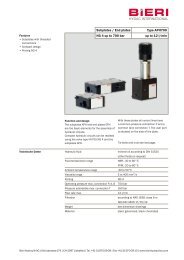
<strong>The</strong> <strong>MP</strong>-C<br />
<strong>Pressure</strong> Intensifi er<br />
er<br />
<strong>The</strong> <strong>MP</strong>-C pressure intensifi er is designed for the cetop-system (D03/NG6) and<br />
will increase a supplied pressure to the higher end pressure required (max. 500<br />
bar).Having high pressure valves incorporated, including the POV (see page 3),<br />
a pilot operated check valve, for relieving the high pressure side, the <strong>MP</strong>-C <strong>of</strong>fers<br />
a cost effective solution for intensifi cation needs. Controlling the high pressure<br />
side is achieved by valves on the low pressure side through the <strong>MP</strong>-C, allowing<br />
the intensifi er to be installed in most existing as well as new hydraulic circuits.<br />
<strong>The</strong> <strong>MP</strong>-C intensifi er is <strong>of</strong>fered with 7 different intensifi cation ratios as standard<br />
with additional ratios on request to meet most intensifi cation requirements.<br />
<strong>The</strong> <strong>MP</strong>-C in a system:<br />
Dimensions in mm<br />
Flow & <strong>Pressure</strong>:<br />
<strong>The</strong> supplied fl ow and pressure to the <strong>MP</strong>-C are dependant on the intensifi cation ratio chosen. <strong>The</strong> table shows the fl ow<br />
and pressure for each model. Flow Q1 is when the pump pressure has been reached, and fl ow Q2 is moving up the vertical<br />
part <strong>of</strong> the curve (see graph on page 2). Please note fl ow values will vary with the viscosity <strong>of</strong> the fl uid. Inlet values<br />
must not be exceeded.<br />
Ratio (i)<br />
Inlet Flow<br />
(LPM / GPM)<br />
Outlet Flow Q1<br />
(LPM / GPM)<br />
Outlet Flow Q2<br />
(LPM / GPM)<br />
Inlet <strong>Pressure</strong><br />
(Bar / Psi)<br />
Outlet <strong>Pressure</strong><br />
(Bar / Psi)<br />
1.5<br />
8.0<br />
/ 2. 1 0.8<br />
/ 0.21<br />
0.3<br />
/ 0.08<br />
200<br />
/ 2,900<br />
300 / 4,350<br />
2.0<br />
8.0<br />
/ 2. 1 0.8<br />
/ 0.21<br />
0.2<br />
/ 0.08<br />
200<br />
/ 2,900<br />
400 / 5,800<br />
3.4<br />
15.0<br />
/ 4. 0 2.2<br />
/ 0.58<br />
0.5<br />
/ 0.13<br />
147<br />
/ 2,132<br />
500 / 7,250<br />
4.0<br />
14.0<br />
/ 3. 7 1.8<br />
/ 0.47<br />
0.4<br />
/ 0.10<br />
125<br />
/ 1,812<br />
500 / 7,250<br />
5.0<br />
14.0<br />
/ 3. 7 1.4<br />
/ 0.37<br />
0.3<br />
/ 0.08<br />
100<br />
/ 1,450<br />
500 / 7,250<br />
7.0<br />
13.0<br />
/ 3. 4 1.1<br />
/ 0.29<br />
0.2<br />
/ 0.05<br />
71<br />
/ 1,036<br />
500 / 7,250<br />
9.0<br />
13.0<br />
/ 3. 4 0.7<br />
/ 0.19<br />
0.1<br />
/ 0.03<br />
56<br />
/ 806<br />
500 / 7,250<br />
Ordering Code:<br />
<strong>MP</strong>- C -<br />
Intensification<br />
1.5<br />
2.<br />
0 3.<br />
4 4.<br />
0 5.<br />
0 7.<br />
0 9. 0<br />
Example:<br />
<strong>MP</strong>-C with intensifi cation 4.0: <strong>MP</strong>-C-4.0<br />
5
<strong>The</strong> <strong>MP</strong>-F <strong>The</strong> <strong>MP</strong>-F<br />
<strong>Pressure</strong> In ten si fi er<br />
<strong>The</strong> <strong>MP</strong>-F pressure intensifi er is a fl ange-on model, designed to be mounted to a hydraulic<br />
block. <strong>The</strong> <strong>MP</strong>-F will increase a supplied pressure to the higher end pressure required (max.<br />
700 bar). Having high pressure valves incorporated, including the POV (see page 3), a pilot<br />
operated check valve, for relieving the high pressure side, the <strong>MP</strong>-F <strong>of</strong>fers a cost effective<br />
solution for intensifi cation needs. Controlling the high pressure side is achieved by valves<br />
on the low pressure side through the <strong>MP</strong>-F, allowing the intensifi er to be installed in most<br />
existing as well as new hydraulic circuits. <strong>The</strong> <strong>MP</strong>-F intensifi er is <strong>of</strong>fered with 5 different intensifi<br />
cation ratios as standard with additional ratios on request to meet most intensifi cation<br />
requirements.<br />
Dimensions in mm<br />
Flow & <strong>Pressure</strong>:<br />
<strong>The</strong> supplied fl ow and pressure to the <strong>MP</strong>-F are dependant on the intensifi cation ratio chosen. <strong>The</strong> table shows the fl ow<br />
and pressure for each model. Flow Q1 is when the pump pressure has been reached, and fl ow Q2 is moving up the vertical<br />
part <strong>of</strong> the curve (see graph on page 2). Please note fl ow values will vary with the viscosity <strong>of</strong> the fl uid. Inlet values<br />
must not be exceeded.<br />
Ratio (i)<br />
Inlet Flow<br />
(LPM / GPM)<br />
Outlet Flow Q1<br />
(LPM / GPM)<br />
Outlet Flow Q2<br />
(LPM / GPM)<br />
Inlet <strong>Pressure</strong><br />
(Bar / Psi)<br />
Outlet <strong>Pressure</strong><br />
(Bar / Psi)<br />
2.0<br />
8.0<br />
/ 2. 1 0.8<br />
/ 0.21<br />
0.2<br />
/ 0.08<br />
200<br />
/ 2,900<br />
400 / 5,800<br />
3.4<br />
15.0<br />
/ 4. 0 2.2<br />
/ 0.58<br />
0.5<br />
/ 0.13<br />
200<br />
/ 2,900<br />
680 / 9,860<br />
4.0<br />
14.0<br />
/ 3. 7 1.8<br />
/ 0.47<br />
0.4<br />
/ 0.10<br />
175<br />
/ 2,538<br />
700 / 10,150<br />
5.0<br />
14.0<br />
/ 3. 7 1.4<br />
/ 0.37<br />
0.3<br />
/ 0.08<br />
140<br />
/ 2,030<br />
700 / 10,150<br />
7.0<br />
13.0<br />
/ 3. 4 1.1<br />
/ 0.29<br />
0.2<br />
/ 0.05<br />
100<br />
/ 1,450<br />
700 / 10,150<br />
Ordering Code: <strong>MP</strong>- F -<br />
Intensification<br />
2.0<br />
3.<br />
4 4.<br />
0 5.<br />
0 7. 0<br />
Example:<br />
<strong>MP</strong>-F with intensifi cation 4.0: <strong>MP</strong>-F-4.0<br />
6
<strong>The</strong> <strong>The</strong> <strong>MP</strong>-2000 <strong>MP</strong>-T<br />
<strong>Pressure</strong> Intensifi er er<br />
<strong>The</strong> <strong>MP</strong>-2000 is an in-line pressure intensifi er designed to be positioned in a low pressure<br />
hydraulic system, and will provide higher pressure exactly where needed (max. 2.000 bar).<br />
Having all the required high pressure valves incorporated, the need for additional high pressure<br />
components is minimized ensuring a cost effective system. Controlling the high pressure<br />
side is achieved by valves on the low pressure side through the intensifi er adding to safety.<br />
<strong>The</strong> intensifi ers are <strong>of</strong>fered with 4 different intensifi cation ratios to meet most intensifi cation<br />
requirements. <strong>The</strong> compact design ensures easy installation in new as well as existing hydraulic<br />
circuits.<br />
<strong>The</strong> <strong>MP</strong>-2000 is <strong>of</strong>fered with a pilot operated check valve (POV) integrated, which allows the<br />
high pressure side to be relieved through the intensifi er (see page 3).<br />
P and T connections: 1/4“ BSP<br />
Dimensions in mm<br />
Flow & <strong>Pressure</strong>:<br />
<strong>The</strong> supplied fl ow and pressure to the <strong>MP</strong>-2000 are dependant on the intensifi cation ratio chosen. <strong>The</strong> table shows the<br />
fl ow and pressure for each intensifi cation ratio. Flow Q1 is when the pump pressure has been reached, and fl ow Q2 is<br />
moving up the vertical part <strong>of</strong> the curve (see graph on page 2). Please note fl ow values will vary with the viscosity <strong>of</strong> the<br />
fl uid. Inlet values must not be exceeded.<br />
Ratio (i)<br />
Inlet Flow<br />
(LPM / GPM)<br />
Outlet Flow Q1<br />
(LPM / GPM)<br />
Outlet Flow Q2<br />
(LPM / GPM)<br />
Inlet <strong>Pressure</strong><br />
(Bar / Psi)<br />
Outlet <strong>Pressure</strong><br />
(Bar / Psi)<br />
7.0<br />
12.0<br />
/ 3.17<br />
1.1<br />
/ 0.29<br />
0.2<br />
/ 0.05<br />
200<br />
/ 2,900<br />
1.400 / 20,300<br />
10.0<br />
12.0<br />
/ 3.17<br />
0.7<br />
/ 0.18<br />
0.2<br />
/ 0.05<br />
200<br />
/ 2,900<br />
2.000 / 29,000<br />
13.0<br />
10.0<br />
/ 2.64<br />
0.5<br />
/ 0.13<br />
0.1<br />
/ 0.02<br />
154<br />
/ 2,233<br />
2.000 / 29,000<br />
16.0<br />
14.0<br />
10.0/<br />
2.64<br />
0.4<br />
/ 0.10<br />
0.1<br />
/ 0.02<br />
125<br />
/ 1.812<br />
2.000 / 29,000<br />
Ordering Code:<br />
<strong>MP</strong>- 2000 - -<br />
NO<br />
POV<br />
S<br />
Intensification<br />
7.0<br />
10.<br />
0 13.<br />
0 16. 0<br />
Example:<br />
<strong>MP</strong>-2000 with the POV integrated and<br />
intensifi cation 7.0: <strong>MP</strong>-2000-P-7.0<br />
YES<br />
P<br />
7
<strong>The</strong> <strong>MP</strong>-M<br />
<strong>Pressure</strong> In ten si fi er<br />
<strong>The</strong> <strong>MP</strong>-M pressure intensifi er is an in-line model, designed to be positioned in a low pressure<br />
hydraulic system, and will provide high pressure exactly where needed. <strong>The</strong> <strong>MP</strong>-M will<br />
automatically increase a supplied pressure to the higher end pressure required (max. 800 bar).<br />
Having high pressure valves incorporated, including the POV (see page 3), a pilot operated<br />
check valve for relieving the high pressure side, the <strong>MP</strong>-M <strong>of</strong>fers a cost effective solution for<br />
intensifi cation needs. Controlling the high pressure side is done by valves on the low pressure<br />
side through the <strong>MP</strong>-M, allowing the intensifi er to be installed in most existing as well<br />
as new hydraulic circuits. <strong>The</strong> <strong>MP</strong>-M intensifi er is <strong>of</strong>fered with 5 different intensifi cation ratios<br />
as standard with additional ratios on request to meet most intensifi cation requirements.<br />
All connections are 3/8“ BSP<br />
All Dimensions in mm<br />
Flow & <strong>Pressure</strong>:<br />
<strong>The</strong> supplied fl ow and pressure to the <strong>MP</strong>-M are dependant on the intensifi cation ratio chosen. <strong>The</strong> table shows the fl ow<br />
and pressure for each model. Flow Q1 is when the pump pressure has been reached, and fl ow Q2 is moving up the vertical<br />
part <strong>of</strong> the curve (see graph on page 2). Please note fl ow values will vary with the viscosity <strong>of</strong> the fl uid. Inlet values<br />
must not be exceeded.<br />
Ratio (i)<br />
Inlet Flow<br />
(LPM / GPM)<br />
Outlet Flow Q1<br />
(LPM / GPM)<br />
Outlet Flow Q2<br />
(LPM / GPM)<br />
Inlet <strong>Pressure</strong><br />
(Bar / Psi)<br />
Outlet <strong>Pressure</strong><br />
(Bar / Psi)<br />
1.8<br />
25.0<br />
/ 6. 6 5.0<br />
/ 1.32<br />
1.5<br />
/ 0.39<br />
200<br />
/ 2,900<br />
360 / 5,220<br />
3.4<br />
35.0<br />
/ 9. 3 5.0<br />
/ 1.32<br />
2.8<br />
/ 0.74<br />
200<br />
/ 2,900<br />
680 / 9,860<br />
4.0<br />
35.0<br />
/ 9. 3 4.0<br />
/ 1.06<br />
2.4<br />
/ 0.63<br />
200<br />
/ 2,900<br />
800 / 11,600<br />
5.0<br />
35.0<br />
/ 9. 3 3.5<br />
/ 0.93<br />
1.9<br />
/ 0.50<br />
160<br />
/ 2,320<br />
800 / 11,600<br />
7.0<br />
35.0<br />
/ 9. 3 3.0<br />
/ 0.80<br />
1.3<br />
/ 0.34<br />
114<br />
/ 1,653<br />
800 / 11,600<br />
Ordering Code:<br />
Example:<br />
<strong>MP</strong>-M with intensifi cation 4.0: <strong>MP</strong>-M-4.0<br />
<strong>MP</strong>- M -<br />
Intensification<br />
1.8<br />
3.<br />
4 4.<br />
0 5.<br />
0 7. 0<br />
8
<strong>The</strong> <strong>MP</strong>-L<br />
<strong>Pressure</strong> In ten si fi er<br />
<strong>The</strong> <strong>MP</strong>-L pressure intensifi er is an in-line model, designed for high fl ow applications,<br />
where it will provide high pressure exactly where needed. <strong>The</strong> <strong>MP</strong>-L will automatically<br />
increase a supplied pressure to the higher end pressure required (max. 800<br />
bar). Having high pressure valves incorporated, including the POV (see page 3),<br />
a pilot operated check valve for relieving the high pressure side, the <strong>MP</strong>-L <strong>of</strong>fers a<br />
cost effective solution for intensifi cation needs. Controlling the high pressure side is<br />
done by valves on the low pressure side through the <strong>MP</strong>-L, allowing the intensifi er<br />
to be installed in most existing as well as new hydraulic circuits. <strong>The</strong> <strong>MP</strong>-L intensifi er<br />
is <strong>of</strong>fered with 5 different intensifi cation ratios as standard with additional ratios on<br />
request to meet most intensifi cation requirements.<br />
Dimensions in mm<br />
Flow & <strong>Pressure</strong>:<br />
<strong>The</strong> supplied fl ow and pressure to the <strong>MP</strong>-L are dependant on the intensifi cation ratio chosen. <strong>The</strong> table shows the fl ow<br />
and pressure for each model. Flow Q1 is when the pump pressure has been reached, and fl ow Q2 is moving up the vertical<br />
part <strong>of</strong> the curve (see graph on page 2). Please note fl ow values will vary with the viscosity <strong>of</strong> the fl uid. Inlet values<br />
must not be exceeded.<br />
Ratio (i)<br />
Inlet Flow<br />
(LPM / GPM)<br />
Outlet Flow Q1<br />
(LPM / GPM)<br />
Outlet Flow Q2<br />
(LPM / GPM)<br />
Inlet <strong>Pressure</strong><br />
(Bar / Psi)<br />
Outlet <strong>Pressure</strong><br />
(Bar / Psi)<br />
2.0<br />
50.0<br />
/ 13.22<br />
5.0<br />
/ 1.32<br />
2.0<br />
/ 0.30.52<br />
9 200<br />
/ 2,900<br />
400 / 5,800<br />
3.4<br />
80.0<br />
/ 21.16<br />
17.8<br />
/ 4.71<br />
13.0<br />
/ 3.44<br />
200<br />
/ 2,900<br />
680 / 9,860<br />
4.0<br />
80.0<br />
/ 21.16<br />
14.7<br />
/ 3.89<br />
11.0<br />
/ 2.91<br />
200<br />
/ 2,900<br />
800 / 11,600<br />
5.0<br />
80.0<br />
/ 21.16<br />
11.6<br />
/ 3.06<br />
8.8<br />
/ 2.33<br />
160<br />
/ 2,320<br />
800 / 11,600<br />
7.0<br />
80.0<br />
/ 21.16<br />
8.4<br />
/ 2.22<br />
6.3<br />
/ 1.67<br />
114<br />
/ 1,653<br />
800 / 11,600<br />
Ordering Code:<br />
Example:<br />
<strong>MP</strong>-L with intensifi cation 4.0: <strong>MP</strong>-L-P-4.0<br />
<strong>MP</strong>- L - P -<br />
Intensification<br />
2.0<br />
3.<br />
3 4.<br />
0 5.<br />
0 7. 0<br />
9
Specials<br />
Spe cials<br />
& Accessories<br />
Specials:<br />
<strong>The</strong> <strong>MP</strong>-T series <strong>of</strong> hydraulic pressure intensifi ers is ideal for making specials, to meet the market demands. Below are<br />
two examples on specials made for customers.<br />
<strong>The</strong> <strong>MP</strong>-L-2000 is based on the <strong>MP</strong>-L series, and is made for a<br />
concrete bursting application (demolition), where a combination <strong>of</strong><br />
high fl ow and high pressure is needed. <strong>The</strong> <strong>MP</strong>-L-2000 is modifi ed<br />
to deliver pressures up 2,500 Bar.<br />
<strong>The</strong> <strong>MP</strong>-T-R pressure intensifi er is based on the <strong>MP</strong>-T series, but<br />
modifi ed to be inserted in a rotating application, where it rotates<br />
at 1,500 rpm, while intensifying a supplied pressure <strong>of</strong> 30 Bar to<br />
210 Bar.<br />
Accessories:<br />
<strong>The</strong> M-Kit consists <strong>of</strong> two brackets<br />
which can be used to fasten the <strong>MP</strong>-<br />
Intensifi ers to a base plate.<br />
<strong>The</strong> M-Nut is a nut M28 x 1.5 to be<br />
used for mounting the <strong>MP</strong>-T pressure<br />
intensifi er.<br />
<strong>The</strong> NG-6 Top plate is <strong>of</strong>fered to be<br />
used with the <strong>MP</strong>-C pressure intensifi -<br />
er, in situations where a closed top for<br />
the Cetop / NG6 block is required.<br />
10
Application<br />
Examples<br />
<strong>Hydraulic</strong> Workholding Circuits on machine<br />
tools is a major application area for the <strong>MP</strong>-series<br />
<strong>of</strong> hydraulic pressure intensifi ers. Inserting the<br />
intensifi er between the hydraulic system already<br />
on the machine tool and the hydraulic clamping<br />
components allows the higher pressure to be<br />
obtained and controlled from the supply side.<br />
In High Flow Applications ( plastic injection<br />
moulding machines, pressure die casting machines,<br />
demolition tools etc.) the <strong>MP</strong>-intensifi ers are<br />
inserted parallel with a p.o. check valve, which is<br />
designed to take the full fl ow and pressure. This<br />
allows the full pump fl ow to be used to fi ll the<br />
cylinder, and subsequently the end pressure is<br />
delivered by the intensifi er. During retract mode<br />
the external p.o.check valve allows the full fl ow to<br />
go back to tank. This setup allows you to get high<br />
pressure with a minimum <strong>of</strong> loss in cycle time.<br />
In <strong>Hydraulic</strong> Power Packs, the <strong>MP</strong>-intensifi ers<br />
are used to give a high pressure output. This is<br />
achieved without changing the standard setup <strong>of</strong><br />
the standard power pack, and presents a fl exible<br />
and economical way <strong>of</strong> obtaining high pressure.<br />
Using the <strong>MP</strong>-Intensifi ers enables the operation<br />
<strong>of</strong> high pressure tools directly from a low pressure<br />
power pack.<br />
11