Dynex D03 Pattern Directional Control Valves - Royal Hydraulics
Dynex D03 Pattern Directional Control Valves - Royal Hydraulics
Dynex D03 Pattern Directional Control Valves - Royal Hydraulics

You also want an ePaper? Increase the reach of your titles
YUMPU automatically turns print PDFs into web optimized ePapers that Google loves.
SPECIFICATIONS<strong>D03</strong> <strong>Pattern</strong><strong>Directional</strong> <strong>Control</strong> <strong>Valves</strong>Also refer to "<strong>Directional</strong> Valve Features, Selection and OperatingRecommendations" (dynexdcvoperating.pdf)CONTACT INFORMATIONUSA Headquarters<strong>Dynex</strong>/Rivett Inc.770 Capitol DrivePewaukee, WI 53072 U.S.A.Tel: 262-691-2222FAX: 262-691-0312E-mail: sales@dynexhydraulics.comPower Units & Systems<strong>Dynex</strong>/Rivett Inc.54 Nickerson RoadAshland, MA 01721 U.S.A.Tel: 508-881-5110FAX: 508-881-6849E-mail: ashland@dynexhydraulics.comEuropean Sales<strong>Dynex</strong>/Rivett Inc.Unit C5 Steel Close, Little End Road, Eaton Socon,Huntingdon, Cambs. PE19 8TT United KingdomTel: +44 (0) 1480 213980FAX: +44 (0) 1480 405662E-mail: sales@dynexhydraulics.co.ukFor more informationvisit our web site:www.dynexhydraulics.comBROCHURE NOTES:Consult the <strong>Dynex</strong> sales department for a review of any application which requires operating abovethe rated flows or pressures, or higher than normal operating temperatures.Specifications shown were in effect when published. Since errors or omissions are possible, contactyour sales representative for the most current specifications before ordering. <strong>Dynex</strong> reserves the rightto discontinue or change designs at any time without incurring any obligation.DYNEXHigh Pressure <strong>Hydraulics</strong>Copyright © <strong>Dynex</strong>/Rivett Inc. Bulletin dynexvesd03specs-0509
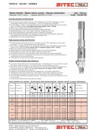
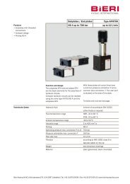
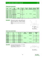
PF3000 <strong>D03</strong> SERIES, PATTERN 10 DESIGNFlow Capacity – Solenoid Models60004005000A350PRESSURE (PSI)4000300020001000BCDEFGH J K30025020015010050PRESSURE (BAR)VALVE DESCRIPTION<strong>D03</strong> valves provide high pressure andhigh flow capability in a very compactsize. Flows to 15 gpm (57 L/min) arepossible at pressures to 5000 psi(350 bar).These valves operate very efficiently, withlarge-core flow passages and uniformflow areas throughout the body coring.Typical pressure drop (open center spool)is a low 98 psi at 8 U.S. gpm (7 bar at30 L/min) nominal flow.For a description of spools, internaloperators and application information,see dynexdcvoperating.pdf.MountingSubplate, N.F.P.A. <strong>D03</strong> (CETOP 3) pattern.Actuator Options6100 Series: Manual Lever;6500 Series: Direct Solenoid;6800 Series: Hydraulic Piloted;6900 Series: Air Piloted.Rated FlowNominal: 8 U.S. gpm (30 L/min);Maximum: 15 U.S. gpm (57 L/min).Rated Pressure5000 psi (350 bar).Tank Port Pressure (Maximum)Manual Actuated Models:3000 psi (210 bar).Solenoid Actuated Models:Standard,1500 psi (105 bar);High Pressure Option (“HT”),AC models, 2300 psi (160 bar);DC models, 3000 psi (210 bar).Hydraulic and Air Actuated Models:1500 psi (105 bar).000 2 4 6 8 10 12 14 160 10 20 30 40 50 60Flow Curve ReferenceSolenoidTypeResponse Time (Full Stroke)Solenoid Energized:AC, 12 ms; DC, 20 ms.Spring Returned:AC, 15 ms; DC, 20 ms.Solenoid OptionsModels are available with standard AC orDC solenoids. Optional Plug-In-TerminalSolenoids fit DIN Connector, Standard43650 Form A (“Hirschmann” type).Electrical ConnectionsStandard Wiring Box with UL listed andCSA approved wire leads;Optional Terminal Strip, Cable Grip orPin Connector (N.F.P.A. standard T3.5-29-1980; A.N.S.I. standard B93.55M-1981).Explosion Proof Option (“EP”)Solenoids with special enclosures areapproved by UL and CSA for use inhazardous locations. Available with AC orDC solenoids.UL Classification:Class I, Group C, D;Class II, Group E, F, G.FLOW (U.S. GPM - L/MIN.)Spool Type0 1 3 4 011 2 2R 32 32R 36 03AC A A H A C E E J J B BDC and "EP" A A A A D K K F F G ACSA/UL Recognized (“C” Option)Solenoid coils are printed withthe symbol:C® (CSA and UL Recognized)This option is available with “115DF”standard AC solenoids only. Foravailability with other voltages, contactthe <strong>Dynex</strong> sales department.VALVE FLOW CAPACITYFlow capacity depends on valve actuator,internal operator and spool type.Solenoid ModelsThe flow capacity curves, above, showtypical performance for each spool type.The letters in the “Flow Curve Reference”table identify the appropriate curve.Lever Operated ModelsMost manual models are rated for15 U.S. gpm (57 L/min) maximum. Theexception is model 613011-<strong>D03</strong> whichis rated for 13 U.S. gpm (49 L/min)maximum. This model has a Code 3internal operator (two position, detentedoperation) with Type 011 spool (tandemcenter).2
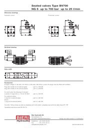
PF3000 <strong>D03</strong> SERIES, PATTERN 10 DESIGNPilot Operated ModelsThe nominal flow capacity for most pilotoperated valves is 15 U.S. gpm (57 L/min).When using a Type 011 spool (tandemcenter, open cross over), the maximumflow is 10 U.S. gpm (38 L/min).Maximum flow for pilot operated valvesis dependent on pilot pressure. The tableshows the minimum pressure required toshift the spool, for various flow capacities.Maximum Pilot Pressure:Hydraulic, 3000 psi (210 bar);Air, 200 psi (14 bar).Required Volume (to shift spool full stroke):Hydraulic, 0.014 in 3 (0,23 cm 3 );Air, 0.220 in 3 (3,61 cm 3 ).Minimum Pilot PressureSeries(ActuatorType)SpoolType5 U.S. gpm(19 L/min)Pilot Pressure at:8 U.S. gpm(30 L/min)15 U.S. gpm(57 L/min)psi bar psi bar psi bar6800 Series 4 130 9,0 165 11,4 200 13,8(HydraulicPiloted) 011, 2 or 2R 190 13,1 275 19,0 – –0 130 9,0 165 11,4 200 13,81 150 10,3 165 11,4 420 29,03 145 10,0 165 11,4 180 12,432 or 32R 150 10,3 200 13,8 – –6900 Series(Air Piloted)36 150 10,3 200 13,8 350 24,103 130 9,0 165 11,4 200 13,80 25 1,7 28 1,9 33 2,31 21 1,4 22 1,5 24 1,73 or 4 25 1,7 28 1,9 34 2,3011 23 1,6 40 2,8 – –2 or 2R 23 1,6 40 2,8 – –32 or 32R 25 1,7 30 2,1 – –36 25 1,7 28 1,9 34 2,303 25 1,7 28 1,9 33 2,3 The values listed are based on zero tank pressure. As back-pressure increases above zero, the minimumpilot pressure must be increased by the same amount.VALVE EFFICIENCY<strong>D03</strong> valves provide exceptionallylow pressure drop, as shown in theperformance curves.Determining Pressure DropThe curves show typical resistance toflow for various spool types. The tableidentifies the proper pressure drop curvefor each spool and flow path.An ExampleIn the table under spool Type 1, curve “C”is called out to determine the pressuredrop for P→A. Looking at the curves, “C”indicates a drop of about 55 psi at 8 U.S.gpm (3,8 bar at 30 L/min).To determine total “loop” drop, theindividual pressure drops for P→A andB→T (or P→B and A→T) must be added.Pressure Drop (∆P)Flow Curve ReferenceFlowPathSpool Type0 1 3 4 011 2 2R 32 32R 36 03P→A B C B C C C C B B B BP→B B C B C C C C B B B BA→T E F F E C C C E F G –B→T E F F E C C C F E G –P→T – D – – A A A – – – –3
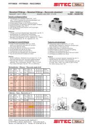
PF3000 <strong>D03</strong> SERIES, PATTERN 10 DESIGNTYPICAL MODEL CODE6 5 4 0 – <strong>D03</strong> – 115DF – R – T – ✳ – 1 06Valve TypeSubplate Mounted<strong>Directional</strong> <strong>Control</strong>Actuator1 Manual Lever5 Solenoid Operated8 Hydraulic Piloted9 Air Piloted123Internal OperatorTwo Position: Spring Offset (P→B),Actuator Offset (P→A)Two Position: Spring Offset (P→A),Actuator Offset (P→B)Two Position: Actuator Offset, Detented; Three Position: Detented (Manual Lever Only)4 Two Position: Spring Centered, Actuator Offset ➂5 Three Position: Spring Centered, Actuator Offset6 Two Position: Spring Offset, Actuator Centered ➃7 Two Position: Detented (Manual Lever Only) Only available with Type 0, 1 and 03 spools. Not available with Manual Lever valves.➂ For most spools, normal flow is actuator offset P→A.For Spool Type 011 (tandem center) normal flow isactuator offset P→B.➃ For most spools, normal flow is spring offset P→B.For Spool Type 011 (tandem center) normal flow isspring offset P→A.A BSpools0 2 P TA BP T<strong>D03</strong>Valve SizeN.F.P.A. <strong>D03</strong>(CETOP 3)Mounting<strong>Pattern</strong>Reverse Flow OptionRBH3ABH3BBH5ABH5BCCGHTMSLTReverse Flow(Code 4 andCode 6 InternalOperators Only)Lever Position (Manual Models Only)A12A3A6A9B12B3B6B9Solenoid OptionsDesign NumberModification Number12 o'clock positon, port "A" end3 o'clock positon, port "A" end6 o'clock positon, port "A" end9 o'clock positon, port "A" end12 o'clock positon, port "B" end3 o'clock positon, port "B" end6 o'clock positon, port "B" end9 o'clock positon, port "B" end3-pin Connector for single solenoid models on port "A" end ➂3-pin Connector for single solenoid models on port "B" end ➂5-pin Connector for single or double solenoid models on port "A" end ➂5-pin Connector for single or double solenoid models on port "B" end ➂CSA and UL Recognized Coils (Etched with Symbol) ➃Cable Grip for .38 to .44 inch (9,5 to 11,1 mm) O.D. machine tool cable High Pressure Tank Port: 2300 psi (160 bar) maximum AC models;3000 psi (210 bar) maximum DC modelsHand Actuated Manual Override Solenoid Lights (available 115DF AC only) Terminal Strip Option not available with “EP” solenoid models. Option not available with “Plug-In Terminal” solenoid models.➂ N.F.P.A. standard T3.539-1980; A.N.S.I. standard B93.55M-1981.➃ Available with 115DF solenoids only.A B1 2R P TA B3 32 P TA B4 32R P TA B011 36 P T03 Not available with Type 3 Internal Operators(except Manual Lever models). Open Crossover.A BP TA BP TA BP TA BP TA BP TElectrical OptionsStandard AC Solenoids (Dual Frequency): Standard DC Solenoids:24DF 24V/60Hz, 24V/50Hz 12DC 12VDC115DF 115V/60HZ, 110V/50Hz 24DC 24VDC230DF 230V/60Hz, 220V/50Hz460DF 460V/60Hz, 440V/50HzPlug-In Terminal AC Solenoids: Plug-In Terminal DC Solenoids: 115HA 115V/60Hz, 110V/50Hz 12HD 12VDC230HA 230V/60Hz, 220V/50Hz 24HD 24VDCExplosion-Proof AC Solenoids:Explosion-Proof DC Solenoids:115EP 115V/60Hz 12EP 12VDC110EP 110V/50Hz 24EP 24VDC220EP 220V/50Hz Fits DIN Connector Standard 43650 Form A (“Hirschmann” type).6