Trouble Shooting Directory for Three Phase Locomotives - eLocoS
Trouble Shooting Directory for Three Phase Locomotives - eLocoS
Trouble Shooting Directory for Three Phase Locomotives - eLocoS

You also want an ePaper? Increase the reach of your titles
YUMPU automatically turns print PDFs into web optimized ePapers that Google loves.
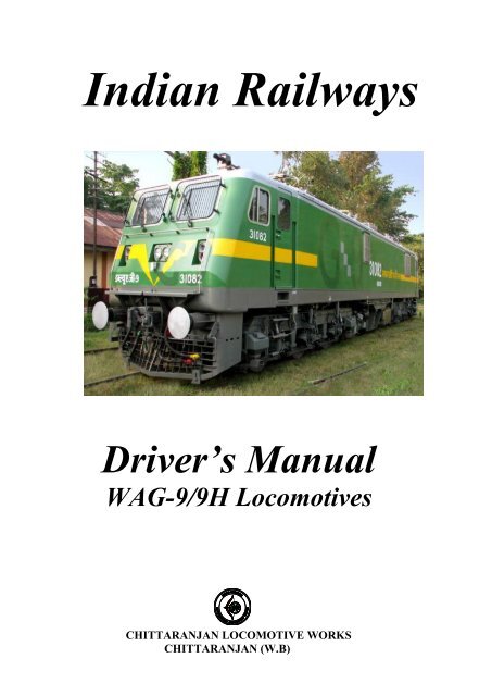
Indian Railways<br />
Driver’s Manual<br />
WAG-9/9H <strong>Locomotives</strong><br />
CHITTARANJAN LOCOMOTIVE WORKS<br />
CHITTARANJAN (W.B)
Driver’s Manual<br />
(Maintenance Manual, Vol-1)<br />
For WAG-9/9H <strong>Locomotives</strong><br />
‣ GENERAL NOTE:<br />
Any suggestion / representation / review request to<br />
be submitted to :–<br />
Dy.CEE / Design<br />
Chittaranjan Locomotive Works.<br />
Chittaranjan; Dist- Burdwan;<br />
State- West Bengal; Pin-713331;<br />
Phone No- 0341-2525546 (BSNL)<br />
Phone No- 40214 (RAIL)<br />
E mail – dyceeclw@gmail.com<br />
Fax- 0341-2525644<br />
CHITTARANJAN LOCOMOTIVE WORKS<br />
CHITTARANJAN (W.B)
INDIAN RAILWAYS<br />
Driver's Manual <strong>for</strong> WAG-9<br />
Contents<br />
Contents<br />
1 Introduction 1-1<br />
1.1 Use of the Driver’s Manual 1-1<br />
1.2 Inspection sheet <strong>for</strong> amendments 1-2<br />
1.3 Abbreviations 1-3<br />
2 Brief description of the loco 2-1<br />
2.1 Mechanical features 2-1<br />
2.2 Electrical Features 2-2<br />
2.3 Technical Data 2-5<br />
2.4 Layout of locomotive 2-7<br />
2.4.1 Overview 2-7<br />
2.4.1.1 Roof layout 2-8<br />
2.4.1.2 Underframe layout 2-9<br />
2.4.1.3 Bogie layout 2-10<br />
2.4.2 Machine room 2-11<br />
2.4.3 Driver’s Cab 2-12<br />
2.5 Tractive /Braking ef<strong>for</strong>t 2-14<br />
2.5.1 Tractive ef<strong>for</strong>t/ speed-diagram (at wheel rim) 2-14<br />
2.5.2 Push/Pull Diagram 2-15<br />
3 System description 3-1<br />
3.1 Braking Concept, Overview 3-1<br />
3.1.1 Regenerative brake 3-1<br />
3.1.2 Main diagram pneumatic brake systems 3-3<br />
3.1.2.1 Pneumatic Automatic train brake 3-4<br />
3.1.2.2 Direct brake (pneumatic) 3-6<br />
3.1.2.3 Parking brake 3-7<br />
3.1.2.4 Emergency braking 3-9<br />
3.2 Driving 3-10<br />
3.2.1 Reverser 3-10<br />
3.2.2 TE/BE Throttle 3-11<br />
CHITTARANJAN LOCOMOTIVE WORKS<br />
Ident. No. 3EHW411116 Ver-1 Content -Page - 1
INDIAN RAILWAYS<br />
Driver's Manual <strong>for</strong> WAG9<br />
Contents<br />
3.2.3 TE/BE meters 3-11<br />
3.2.4 Constant Speed Control (CSC) 3-12<br />
3.2.5 Speedometer 3-12<br />
3.2.6 Limitation of acceleration / deceleration 3-13<br />
3.2.7 Anti-spin protection/anti-slide protection 3-13<br />
3.2.8 Sanding 3-14<br />
3.2.9 Train parting 3-14<br />
3.2.10 Wheel flange lubrication (deleted) 3-14<br />
3.3 Traction equipment 3-15<br />
3.3.1 General description 3-16<br />
3.3.2 Main trans<strong>for</strong>mer 3-17<br />
3.3.3 Converter Unit 3-19<br />
3.3.3.1 Line Converter (NSR) 3-20<br />
3.3.3.2 DC-Link 3-20<br />
3.3.3.3 Drive Converter 3-21<br />
3.3.3.4 Main diagram traction converter 3-21<br />
3.3.4 Traction motors 3-22<br />
3.4 Auxiliary circuit equipment 3-22<br />
3.4.1 Auxiliary circuits 3-23<br />
3.4.1.1 Starting cycle <strong>for</strong> one compressor 3-24<br />
3.4.1.2 Starting cycle <strong>for</strong> two compressors 3-24<br />
3.4.2 Single phase 415/110 V auxiliary circuit 3-25<br />
3.4.2.1 Single phase 415/110 V auxiliary circuit 3-26<br />
3.4.3 Ventilation system 3-27<br />
3.4.3.1 General 3-27<br />
3.4.3.2 Scavenge Blowers 3-28<br />
3.4.4 Cooling concept 3-29<br />
3.4.4.1 Oil pumps 3-29<br />
3.4.5 Generation of compressed air 3-30<br />
3.4.5.1 Main compressors 3-30<br />
3.4.5.2 Operating modes 3-30<br />
3.4.5.2.1 Operating mode “OFF” 3-30<br />
3.4.5.2.2 Operating mode “AUTO” 3-30<br />
3.4.5.2.3 Operating mode “MAN” 3-31<br />
3.4.5.3 Auxiliary compressor 3-31<br />
3.4.5.4 Air dryers 3-31<br />
CHITTARANJAN LOCOMOTIVE WORKS<br />
Ident No. 3EHW411172 Ver-1 Content- Page- 2
INDIAN RAILWAYS<br />
Driver's Manual <strong>for</strong> WAG9<br />
Contents<br />
3.5 Control circuit 3-31<br />
3.5.1 Battery 3-31<br />
3.5.2 Control current distribution 3-32<br />
3.6 Control electronics 3-32<br />
3.6.1 General 3-32<br />
3.6.2 Bus concept 3-33<br />
3.6.3 Bus station 3-34<br />
3.6.4 Third party control electronics 3-34<br />
3.7 Safety systems 3-35<br />
3.7.1 Vigilance control module (Automatic Vigilance Control) 3-35<br />
3.7.1.1 Dead man mode 3-35<br />
3.7.1.2 Resetting of penalty brake Vigilance mode 3-35<br />
3.7.1.3 Vigilance mode 3-36<br />
3.7.1.4 Alarm operation 3-36<br />
3.7.2 Fire detection system 3-37<br />
3.7.2.1 Reset of the fire alarm 3-38<br />
3.7.3 Fire extinguishers 3-38<br />
3.8 Com<strong>for</strong>t equipment 3-39<br />
3.8.1 Ventilation/Heating 3-39<br />
3.8.1.1 Fan 3-39<br />
3.8.1.2 Cab ventilation/heating (recirculating air blower) 3-39<br />
3.8.1.3 Forced ventilation 3-39<br />
3.9 Windshield wiper/washer unit 3-39<br />
3.10 Protection concept 3-40<br />
3.10.1 General 3-40<br />
3.10.2 Interlocking concept (<strong>for</strong> Maintenance / Repair) 3-40<br />
3.10.3 Protective measures 3-43<br />
3.10.3.1 Protective shut down 3-43<br />
3.10.3.2 Disturbance with VCB “OFF” 3-44<br />
3.10.3.3 Traction interlock 3-44<br />
3.10.3.4 Start/Running Interlock 3-45<br />
3.10.4 Catenary Voltage 3-46<br />
CHITTARANJAN LOCOMOTIVE WORKS<br />
Ident No. 3EHW411172 Ver-1 Content- Page- 3
INDIAN RAILWAYS<br />
Driver's Manual <strong>for</strong> WAG9<br />
Contents<br />
3.10.5 Trans<strong>for</strong>mer 3-46<br />
3.10.6 Line Converter 3-47<br />
3.10.7 Traction Motors 3-48<br />
3.10.8 Auxiliary Converter (BUR) 3-49<br />
3.10.9 Oil Pump and Fan 3-49<br />
3.10.10 Battery 3-50<br />
3.10.11 Control electronics 3-50<br />
3.10.11.1 Reciprocal monitoring of the processors 3-50<br />
3.10.11.2 Train bus 3-51<br />
3.10.11.3 VCB 3-51<br />
3.10.11.4 Converter 3-51<br />
3.10.11.5 Software 3-52<br />
3.10.11.6 CEL Temperature 3-52<br />
3.10.11.7 Speed sensors on traction motor 3-52<br />
3.10.11.8 Harmonic Filter circuit 3-52<br />
3.11 Redundancy 3-52<br />
3.11.1 Auxiliary circuit 3-53<br />
3.11.2 Traction motor 3-53<br />
3.11.3 Central Electronics (CEL) 3-53<br />
3.11.3.1 Failure of HBB1 3-53<br />
3.11.3.2 Failure of HBB2 3-54<br />
3.11.3.3 Failure of STB1 3-54<br />
3.11.3.4 Failure of STB2 3-55<br />
3.11.3.5 Failure of FLG1 3-55<br />
3.11.3.6 Failure of FLG2 3-56<br />
3.11.3.7 Failure of DDA1 3-56<br />
3.11.3.8 Failure of DDA2 3-56<br />
3.11.3.9 Failure of DIA1 3-56<br />
3.12 Simulation more 3-57<br />
3.12.1 General 3-57<br />
3.12.2 Setting up and simulation of driving 3-57<br />
3.12.3 Simulation of other functions 3-58<br />
4 Vehicle Operation 4-1<br />
4.1 Over view Driver’s Cab 4-2<br />
CHITTARANJAN LOCOMOTIVE WORKS<br />
Ident No. 3EHW411172 Ver-1 Content- Page- 4
INDIAN RAILWAYS<br />
Driver's Manual <strong>for</strong> WAG9<br />
Contents<br />
4.2 Operating Concept 4-3<br />
4.3 Controls 4-4<br />
4.3.1 Panel A 4-4<br />
4.3.2 Panel B 4-5<br />
4.3.3 Panel C 4-6<br />
4.3.4 Panel D 4-7<br />
4.3.5 Windshield wiper/washer unit 4-8<br />
4.3.6 Com<strong>for</strong>t Equipment 4-9<br />
4.3.7 Detailed layout of light switches and sockets (driver’s cab) 4-10<br />
4.3.8 Details layout of light switches and sockets (machine room) 4-11<br />
4.3.9 Auxiliary circuits, Cubicle-1 (HB1) 4-12<br />
4.3.10 Auxiliary circuits, Cubicle-2 (HB2) 4-14<br />
4.3.11 Control Cubicle – 1 (SB1) 4-16<br />
4.3.12 Control Cubicle – 2 (SB2) 4-18<br />
4.3.13 Filter Cubicle 4-20<br />
4.3.14 Converter Unit 4-21<br />
4.3.15 Front of pneumatic panel 4-22<br />
4.3.15.1 Back face of pneumatic panel 4-24<br />
4.3.16 Outside controls (symmetrical on both sides of the loco) 4-25<br />
4.3.17 Lighting and outside connections 4-26<br />
4.4 Driving/Braking 4-27<br />
4.4.1 Drivers inspection (Commissioning) 4-27<br />
4.4.1.1 Preparations 4-27<br />
4.4.1.2 Activating driver’s cab 4-29<br />
4.4.1.3 Raising the Pantograph 4-31<br />
4.4.1.4 Closing Main Circuit Breaker 4-32<br />
4.4.1.5 Switching on the Main Compressors 4-33<br />
4.4.1.5.1 Operating Mode “OFF” 4-33<br />
4.4.1.5.2 Operating Mode “AUTO” 4-33<br />
4.4.1.5.3 Operating Mode “MAN” 4-34<br />
4.4.2 Driving/Braking 4-35<br />
4.4.2.1 Driving 4-36<br />
4.4.2.2 Braking 4-36<br />
4.4.2.3 Emergency Braking 4-37<br />
4.4.3 Shutting down 4-37<br />
4.4.3.1 Switch Off Main Circuit Breaker 4-37<br />
4.4.3.2 Lower Pantograph 4-38<br />
CHITTARANJAN LOCOMOTIVE WORKS<br />
Ident No. 3EHW411172 Ver-1 Content- Page- 5
INDIAN RAILWAYS<br />
Driver's Manual <strong>for</strong> WAG9<br />
Contents<br />
4.4.3.3 Deactivating Driver’s Cab 4-38<br />
4.4.3.4 Active functions with deactivated driver’s cab 4-39<br />
4.4.3.5 Knorr,s brake system 4-39<br />
4.5 Changing the driver’s cab 4-43<br />
4.5.1 Single unit running 4-43<br />
4.5.2 Multiple operation 4-43<br />
4.6 Automatic Vigilance 4-44<br />
4.6.1 Vigilance Mode 4-44<br />
4.6.2 Triggering alarm 4-44<br />
4.6.3 Dead man mode 4-45<br />
4.6.4 Resetting after Penalty Brakes 4-45<br />
4.6.5 Fire alarm 4-45<br />
4.7 SPEEDOMETER 4-46<br />
4.7.1 Controls and displays 4-46<br />
4.7.2 Functions and settings 4-47<br />
4.7.2.1 Self test 4-47<br />
4.7.2.2 Adjustment of brightness 4-48<br />
4.7.2.3 Indication lamps 4-48<br />
4.7.2.3.1 Indication Lamp <strong>for</strong> System / Memory fault 4-48<br />
4.7.2.3.2 Indication Lamp <strong>for</strong> over Speed 4-48<br />
4.7.2.4 Data Entry Keyboard 4-48<br />
4.7.2.5 Digital display 4-49<br />
4.7.2.6 Memory Freeze 4-49<br />
4.7.2.7 Reading / Downloading of the recorded Data 4-49<br />
4.8 Constant Speed Control (CSC) 4-50<br />
4.9 Neutral Section 4-50<br />
4.10 Multiple Operation 4-51<br />
4.10.1 Multiple operation with two locomotives 4-51<br />
4.10.1.1 Pantograph 4-51<br />
4.10.1.2 Main Circuit Breaker 4-52<br />
4.10.1.3 Regenerative Brake 4-52<br />
4.10.1.4 Constant Speed Control (CSC) 4-52<br />
CHITTARANJAN LOCOMOTIVE WORKS<br />
Ident No. 3EHW411172 Ver-1 Content- Page- 6
INDIAN RAILWAYS<br />
Driver's Manual <strong>for</strong> WAG9<br />
Contents<br />
4.10.1.5 Anti-spin protection 4-52<br />
4.10.1.6 Compressor control 4-52<br />
4.10.1.7 Parking Brake 4-53<br />
4.10.1.8 Emergency Brake 4-53<br />
4.10.1.9 Other Brake Functions 4-54<br />
4.10.2 Coupling 4-54<br />
4.10.3 Uncoupling 4-55<br />
4.10.4 Sanding 4-55<br />
4.10.5 Fire alarm 4-56<br />
4.11 Trailing mode 4-56<br />
4.12 Banking mode 4-56<br />
4.13 Towing mode 4-57<br />
4.13.1 Making a live locomotive dead & then towing it 4-57<br />
4.13.2 Making a dead locomotive ready <strong>for</strong> towing 4-58<br />
4.13.3 Towing a dead locomotive (when no breaks applied on it ) 4-59<br />
4.14 Failure mode operation 4-60<br />
4.14.1 Definition 4-60<br />
4.14.2 Driving in failure mode 4-60<br />
4.15 In<strong>for</strong>mation on display screen 4-61<br />
4.15.1 General 4-61<br />
4.15.2 Operation of display screen 4-62<br />
4.15.3 Screen structure 4-63<br />
4.15.4 Stand-by screen 4-64<br />
5 Faults 5-1<br />
5.1 General 5-1<br />
5.1.1 Fault message priorities 5-1<br />
5.1.2 Isolating sub-systems 5-1<br />
5.1.2.1 Overview of sub-systems 5-2<br />
5.1.2.2 Restrictions due to isolating of various sub-systems 5-3<br />
5.1.3 Acknowledgement of fault messages 5-3<br />
5.1.3.1 Fault messages with priority 1 5-3<br />
5.1.3.2 Fault messages with priority 2 5-4<br />
CHITTARANJAN LOCOMOTIVE WORKS<br />
Ident No. 3EHW411172 Ver-1 Content- Page- 7
INDIAN RAILWAYS<br />
Driver's Manual <strong>for</strong> WAG9<br />
Contents<br />
5.1.3.3 Resetting the status of the locomotive 5-4<br />
5.1.4 Status display of the sub-systems 5-5<br />
5.1.4.1 Select Main Menu Screen 5-5<br />
5.1.4.2 Select Vehicle Diagnostics (move “>” with arrow keys) 5-5<br />
5.1.5 Key to Codes 5-5<br />
5.1.6 Browse 5-6<br />
5.1.7 Train Configuration 5-7<br />
5.1.8 Energy Consumption 5-8<br />
5.2 Earthling 5-8<br />
5.3 Fault / Isolation messages 5-9<br />
5.3.1 Fault message display 5-9<br />
5.3.1.1 Example 5-9<br />
5.3.1.1.1 Explanations 5-9<br />
5.4 List of Fault Messages 5-11<br />
5.5 List of Isolation Messages 5-28<br />
5.6 List of In<strong>for</strong>mation Messages 5-30<br />
6 Latest Up gradation 6-1<br />
6.1 Hotel Load (<strong>for</strong> WAP-7 Locomotive) 6-1<br />
6.2 IGBT Traction Converter based Locomotive 6-5<br />
6-3 Air conditioned cab 6-9<br />
6.4 Loco Trol 6-11<br />
7 Index Index-1<br />
8 Illustrations Illustr.-1<br />
CHITTARANJAN LOCOMOTIVE WORKS<br />
Ident No. 3EHW411172 Ver-1 Content- Page- 8
INDIAN RAILWAYS<br />
Driver's Manual <strong>for</strong> WAG9<br />
Introduction<br />
1. INTRODUCTION:<br />
1.1 Use of the Driver’s Manual:<br />
This Driver’s Manual describes the locomotive characteristics, the technical<br />
options available and the operation of locomotives of the WAG-9, WAG-9H &<br />
WAP-7 Series.<br />
No reference will be made to official railway regulations and restrictions.<br />
A layout has been selected which makes it possible to answer specific questions<br />
by referring to the relevant section. The Driver’s Manual is intended to enable the<br />
user to obtain a more detailed understanding of the various systems and the way<br />
they interact with one another. Above all, trained personnel are recommended to<br />
use the Driver’s Manual in conjunction with circuit diagrams and control<br />
electronics software documents.<br />
The Chapters differ in terms of content, layout and intended target audience in<br />
accordance with the following list:<br />
Chapter<br />
Contents<br />
1 Introduction<br />
2. Brief description of the loco<br />
3. System description<br />
4. Vehicle operation<br />
5. Faults<br />
6. Latest Up gradation<br />
7. Index<br />
8. Illustrations<br />
Item numbers of equipment:<br />
Equipment item numbers are listed down of the left margin.<br />
CHITTARANJAN LOCOMOTIVE WORKS<br />
Ident. No. 3EHW411172 Ver-1 Chap. 1, Page - 1
INDIAN RAILWAYS<br />
Driver's Manual <strong>for</strong> WAG9<br />
Introduction<br />
1.2 Inspection Sheet <strong>for</strong> Amendments:<br />
This final version of the Driver’s Manual <strong>for</strong> the WAG-9 / 9H locomotive was<br />
compiled by Electric Loco Design Office, Chittaranjan Locomotive Works<br />
Chittaranjan.<br />
Version Dept. Issue Date<br />
Checked<br />
by<br />
Approved<br />
by<br />
Comments<br />
Edition<br />
0/VER-1<br />
ELDO/<br />
CRJ<br />
20.02.2011. Ref to Edition 0/en<br />
BTI drivers manual,<br />
ISSUED ON<br />
30.12.2001<br />
CHITTARANJAN LOCOMOTIVE WORKS<br />
Ident. No. 3EHW411172 Ver-1 Chap. 1, Page - 2
INDIAN RAILWAYS<br />
Driver's Manual <strong>for</strong> WAG9<br />
Introduction<br />
1.3 Abbreviations:<br />
ALG Drive Control Unit Drive Inverter and Line Converter<br />
Control<br />
ASC Drive Converter Control<br />
ASR Drive Converter<br />
BL<br />
Key Switch<br />
BLCP Spring-loaded Switch Main compressors AUTO mode<br />
BLDJ Spring-loaded Switch Main circuit breaker<br />
BLHO Spring-loaded Switch Hotel load (not active on WAG-9)<br />
BLPR Switch Headlights<br />
BPCS Illuminated Push-button, Green Constant speed control<br />
BPFA Illuminated Push-button, Yellow Acknowledgement all fault messages<br />
BPFL Illuminated Push-button, Yellow Emergency flash light<br />
BPPB Illuminated Push-button, red Parking brake(not active on WAP-7)<br />
BPVG Push-button, Green Vigilance<br />
BPVR Push-button, Yellow Acknowledge vigilance<br />
BUR Auxiliary Converter<br />
BZ-V-O-F Buzzer<br />
CEL Central Electronics<br />
CSC Constant Speed Control<br />
DDA Display Data Control<br />
DDS Diagnostic Data Set<br />
DIA<br />
Diagnostic Control<br />
FBV Vehicle Bus Administrator<br />
FLG Vehicle Control Unit<br />
GTO Gate Turn Off Switch<br />
HB<br />
Cubicle Auxiliary Circuits<br />
HBB Processor<br />
HRA Switch Cab blower/heating<br />
LSAF Indication Lamp, Red Train parting<br />
LSCE Indication Lamp, Amber Over temperature CEL<br />
LSDJ Indication Lamp, Red Main circuit breaker<br />
LSFI Indication Lamp, Red Fault message, priority 1<br />
LSHO Indication Lamp, Yellow Hotel load (not active on WAG-9)<br />
LSP Indication Lamp, Yellow Wheel slipping<br />
LSVW Indication Lamp, Yellow Vigilance Warning<br />
MCB Main Circuit Breaker<br />
MCE MICAS-S2 Control Electronics<br />
CHITTARANJAN LOCOMOTIVE WORKS<br />
Ident. No. 3EHW411172 Ver-1 Chap. 1, Page - 3
INDIAN RAILWAYS<br />
Driver's Manual <strong>for</strong> WAG9<br />
Introduction<br />
MSC<br />
SPM<br />
MR<br />
MUB<br />
MVB<br />
Master Sequential Control<br />
Speedometer<br />
Machine Room<br />
Over voltage Protection Unit<br />
Multifunction vehicle Bus<br />
NSC Line Converter Control<br />
NSR Line Converter<br />
Pan Pantograph<br />
PCLH Socket Hand lamp<br />
PP<br />
Pneumatic Panel<br />
SB<br />
Cubicle Control Circuits<br />
SLG Converter Control Unit<br />
SR<br />
Traction Converter<br />
STB Low Voltage Cubicle Control<br />
TE/BE Tractive/Braking Ef<strong>for</strong>t<br />
UBA Voltmeter Battery Voltage<br />
UIC<br />
Union International des<br />
chemins de fer<br />
VCB Vacuum Circuit Breaker Main Circuit Breaker<br />
ZBAN Spring loaded Switch Banking Operation<br />
ZBV Train Bus Administrator<br />
ZLC Switch Driver’s cab lighting<br />
ZLDA Switch Assistant Driver’s Desk Illumination<br />
ZLDD Switch Driver’s Desk Illumination<br />
ZLFR Switch Marker Lights, Red<br />
ZLFW Switch Marker Lights, White<br />
ZLH Switch Socket Hand Lamp<br />
ZLI Switch Instrument Lighting<br />
ZPRD Switch Head Light, intensity<br />
ZPT Spring-loaded Switch Pantograph<br />
ZTEL Switch Max. traction limitation<br />
ZK<br />
DC link<br />
CHITTARANJAN LOCOMOTIVE WORKS<br />
Ident. No. 3EHW411172 Ver-1 Chap. 1, Page - 4
INDIAN RAILWAYS<br />
Brief description of the loco<br />
Driver's Manual <strong>for</strong> WAG9<br />
2. BRIEF DESCRIPTION OF THE LOCO:<br />
The WAG-9 &9H is a high-speed main line locomotive <strong>for</strong> hauling FREIGHT trains<br />
and WAP-7 is a high-speed main line locomotive <strong>for</strong> hauling PASSENGER trains.<br />
This locomotive is a double-ended design, which means that there are a driver’s cab<br />
and coupling elements at both ends of the loco.<br />
2.1 Mechanical Features:<br />
The three axles, three motor Co-Co bogie assemblies, is one of the major parts of<br />
the locomotive. Two bogie assemblies support the entire weight of the locomotive<br />
and provide a means <strong>for</strong> transmission of the tractive ef<strong>for</strong>t to the rails.<br />
The bogies are designed to withstand the stresses and vibrations resulting from<br />
normal rolling stock applications. An important function of the bogie is to absorb and<br />
isolate shock caused by variations in the trackbed. The suspension systems<br />
minimize the transmission of these shocks to the locomotive under frame.<br />
The traction motors are suspended in the bogie frame and on the individual axis.<br />
The motors transmit their energy to the driving axles through a gearbox mounted on<br />
the driving axle. The <strong>for</strong>ce from the driving axles is transmitted to the contact point<br />
between the wheel tread and the rail. Traction <strong>for</strong>ce is, in turn, transmitted through<br />
the axle journal boxes and guide rods to the bogie frame. The push-pull link rod,<br />
connected between the bogie transom and car under frame, transmits the tractive<br />
<strong>for</strong>ces to the car body.<br />
The WAG-9/9H is equipped with the following pneumatic braking systems: automatic<br />
train brake, direct loco brake, parking brake, and anti-spin brake. As with the tractive<br />
ef<strong>for</strong>t, braking ef<strong>for</strong>t is transmitted to the bogie frame by the axle journal boxes and<br />
guide rods and from the bogie frame to the locomotive by the traction rods.<br />
Isolation and absorption of shock loads and vibration is per<strong>for</strong>med by the primary<br />
and secondary suspension. Movement between the car body and bogie is smoothly<br />
controlled by the primary and secondary suspension. Although the springs permit<br />
free movement in any direction, lateral buffers and dampers limit the amount and<br />
rate of lateral movement. Rebound limit chains and vertical dampers limit the<br />
amount and rate of the vertical rebound of the locomotive car body. Yaw<br />
(longitudinal) dampers control the car body pitch rate. Guide rods control the <strong>for</strong>e<br />
and aft movement between the axles and the bogie frame, while the link rod controls<br />
the <strong>for</strong>e and aft movement between the bogies and the locomotive car body.<br />
CHITTARANJAN LOCOMOTIVE WORKS<br />
Ident. No. 3EHW411172 Ver-1 Chap. 2, Page - 1
INDIAN RAILWAYS<br />
Brief description of the loco<br />
Driver's Manual <strong>for</strong> WAG9<br />
The primary suspension, located between the axles and the bogie frame, is provided<br />
by twin coil springs on the axle journal box <strong>for</strong>e and aft of the axle line. Vertical<br />
hydraulic dampers are used to dampen the rebound rate of the springs. This “Flexi<br />
coil” arrangement permits lateral movement of the axle. Longitudinal control of the<br />
axle, and the transmission of tractive and braking ef<strong>for</strong>t to the bogie frame, is<br />
provided by guide rods connected between the axle journal boxes and bogie frame.<br />
Spheribloc rubber bushes in the guide rods allow the axle lateral movement without<br />
undue restriction.<br />
Secondary suspension is also provided by coil springs and vertical hydraulic<br />
dampers, located between the bogie frame and the locomotive under frame on each<br />
side of the bogie. The weight of the locomotive car body is carried by the secondary<br />
suspension springs. The “Flexi-Float” arrangement of the secondary suspension<br />
allows the locomotive car body to move both laterally and vertically within certain<br />
limits relative to the bogies.<br />
2.2 Electrical Features:<br />
- Vehicle propulsion concept:<br />
3-phase converter drive.<br />
- Main trans<strong>for</strong>mer<br />
The main trans<strong>for</strong>mer is housed in an aluminium tank. It is mounted underframe<br />
between the two bogies.<br />
- Traction Converter<br />
The machine room contains one traction converter per bogie with 2-point switching.<br />
This comprises a line converter (NSR) and a 3-phase drive converter (ASR).<br />
The traction motors are supplied with power directly by two relevant bogie selective<br />
drive converters with appropriate control electronics.<br />
- Axle drive<br />
<strong>Three</strong> externally ventilated three-phase asynchronous squirrel cage motors of Type<br />
6 FRA 6068 are installed on both bogies. The three traction motors on each bogie<br />
are supplied with power by one traction converter.<br />
CHITTARANJAN LOCOMOTIVE WORKS<br />
Ident. No. 3EHW411172 Ver-1 Chap. 2, Page - 2
INDIAN RAILWAYS<br />
Brief description of the loco<br />
Driver's Manual <strong>for</strong> WAG9<br />
- Harmonic Filter<br />
The harmonic filter consisting of resistor and capacitor reduces the high frequency<br />
harmonics.<br />
- Auxiliary Circuits<br />
<strong>Three</strong> modular auxiliary converters (BUR) are used to supply power to the 3-phase<br />
auxiliary circuit motors. The auxiliary circuits are designed in a bogie-selective<br />
manner.<br />
- Control electronics (MICAS-S2)<br />
All functions of the locomotive are controlled by the control electronics. It takes the<br />
<strong>for</strong>m of bus stations with processors.<br />
The bus stations communicate with each other via fibre optic cables which are<br />
resistant to the effects of Electro Magnetic Interference (EMI). The diagnostic<br />
equipment comprises a diagnosis computer with monitor and keyboard in the<br />
driver’s cab. This provides an effective support <strong>for</strong> the duties of the locomotive driver<br />
and maintenance personnel.<br />
- Multiple Unit Control<br />
The locomotive is equipped <strong>for</strong> multiple unit control with locomotives of the same<br />
kind. However, no more than two locomotives can be connected together.<br />
Commands are transmitted by the UIC cable.<br />
Com<strong>for</strong>t Equipment<br />
Every driver’s cab is equipped with two fans and a unit <strong>for</strong> recirculating and heating<br />
the air.<br />
Recently cab air-condition has been introduced in WAG-9 type locomotive.<br />
CHITTARANJAN LOCOMOTIVE WORKS<br />
Ident. No. 3EHW411172 Ver-1 Chap. 2, Page - 3
INDIAN RAILWAYS<br />
Brief description of the loco<br />
Driver's Manual <strong>for</strong> WAG9<br />
Fig.2.1<br />
Dimension of the locomotive;<br />
A Distance between bogies (center – center) 12000 mm<br />
L Length over buffers 20562 mm<br />
D Distance between axles of bogie 1850 mm<br />
B Overall width 3152 mm<br />
H Max. height with pantograph locked down(Overall) 4255 mm<br />
S Gauge 1676 mm<br />
CHITTARANJAN LOCOMOTIVE WORKS<br />
Ident. No. 3EHW411172 Ver-1 Chap. 2, Page - 4
INDIAN RAILWAYS<br />
Brief description of the loco<br />
Driver's Manual <strong>for</strong> WAG9<br />
2.3 Technical Data:<br />
Customer<br />
Designation<br />
Manufacturer<br />
Axle arrangement<br />
Gear Ratio<br />
Gauge<br />
Length over buffers<br />
Overall width<br />
WAG-9 & 9H<br />
WAP-7<br />
Indian Railways<br />
WAG-9 / 9H & WAP-7<br />
Chittaranjan Locomotive Works,<br />
Chittaranjan (W.B)<br />
Co-Co<br />
107:21<br />
72:20<br />
1676 mm<br />
20562 mm<br />
3152 mm<br />
Max. height with pantograph locked down<br />
Distance between the bogie centers<br />
Distance between axles of bogie<br />
Wheel diameter<br />
New<br />
Half worn<br />
Worn<br />
4255 mm<br />
12000 mm<br />
1850 mm<br />
1092 mm<br />
1054 mm<br />
1016 mm<br />
Maximum permitted difference of wheel diameter on<br />
the same axle.<br />
Maximum permitted difference of wheel diameters<br />
within one bogie<br />
Maximum permitted difference of wheel diameter<br />
between bogies<br />
Sharpest negotiable curve radius<br />
0.5 mm<br />
4 mm<br />
20 mm<br />
174 m<br />
Total weight<br />
(without ballast)<br />
(with ballast <strong>for</strong> WAG-9H)<br />
123 t<br />
132t<br />
CHITTARANJAN LOCOMOTIVE WORKS<br />
Ident. No. 3EHW411172 Ver-1 Chap. 2, Page - 5
INDIAN RAILWAYS<br />
Brief description of the loco<br />
Driver's Manual <strong>for</strong> WAG9<br />
Catenary voltage<br />
Normal<br />
Minimum<br />
Maximum<br />
Brief minimum<br />
Occasionally maximum<br />
25 kV<br />
19 kV<br />
27.5 kV<br />
17.5 kV<br />
30 kV<br />
Frequency 50 Hz +/- 3%<br />
Static power supply to auxiliary circuits<br />
Voltage 415 V +/- 10%<br />
Frequency<br />
Battery voltage<br />
Regenerative brake<br />
Mechanical brake systems:<br />
Maximum braking <strong>for</strong>ce<br />
0 ….. 50 Hz<br />
110 VDC<br />
260 kN<br />
Automatic train brake- Maximum braking <strong>for</strong>ce<br />
Coefficient of adhesion<br />
Parking Brake<br />
Maximum braking <strong>for</strong>ce<br />
Power & FAD of each of the two main compressor<br />
Continuous rating on wheel rim between 80 and 120<br />
km/h<br />
Traction <strong>for</strong>ce on wheel rim between 0 and 50 km/h.<br />
Maximum<br />
Continuous<br />
242 kN<br />
35%<br />
37 kN<br />
15 KW & 1745 l/min<br />
4500 kW<br />
460 kN<br />
325 kN<br />
Maximum Speed (G-9 & 9H)<br />
Maximum ambient temp.<br />
With half worn wheels<br />
At constant speed<br />
In the sun<br />
In the shade<br />
100 km/h<br />
100 km/h<br />
70ºC<br />
50ºC<br />
Minimum ambient temp. 0ºC<br />
Reference to site conditions-<br />
Temperature<br />
Humidity<br />
Height above sea level<br />
47ºC<br />
60%<br />
160 m<br />
CHITTARANJAN LOCOMOTIVE WORKS<br />
Ident. No. 3EHW411172 Ver-1 Chap. 2, Page - 6
INDIAN RAILWAYS<br />
Brief description of the loco<br />
Driver's Manual <strong>for</strong> WAG9<br />
2.4 Layout of locomotive:<br />
2.4.1 Overview:<br />
Fig. 2.2<br />
Layout of the locomotive<br />
1 Roof<br />
2 Driver’s cab<br />
3 Machine Room<br />
4 Bogie<br />
5 Frames<br />
CHITTARANJAN LOCOMOTIVE WORKS<br />
Ident. No. 3EHW411172 Ver-1 Chap. 2, Page - 7
INDIAN RAILWAYS<br />
Brief description of the loco<br />
Driver's Manual <strong>for</strong> WAG9<br />
2.4.1.1 Roof layout:<br />
Fig.2.3<br />
Roof layout<br />
1 Main circuit breaker<br />
2 Transducers<br />
3 Pantograph<br />
4 Resistor harmonic filter<br />
5 Surge arrestor<br />
6 Roof line<br />
CHITTARANJAN LOCOMOTIVE WORKS<br />
Ident. No. 3EHW411172 Ver-1 Chap. 2, Page - 8
INDIAN RAILWAYS<br />
Brief description of the loco<br />
Driver's Manual <strong>for</strong> WAG9<br />
2.4.1.2 Underframe layout:<br />
Fig. 2.4<br />
Underframe layout:<br />
1. Main Compressor (600 kg)<br />
2. Trans<strong>for</strong>mer (9450 kg)<br />
3. Circuit breaker battery<br />
4. Batteries box (Empty Box-234 kg + Battery-374 kg. per box)<br />
CHITTARANJAN LOCOMOTIVE WORKS<br />
Ident. No. 3EHW411172 Ver-1 Chap. 2, Page - 9
INDIAN RAILWAYS<br />
Brief description of the loco<br />
Driver's Manual <strong>for</strong> WAG9<br />
2.4.1.3 Bogie layout:<br />
Fig.2.5 Bogie layout<br />
1 Sanding box<br />
2 Wheel flange lubrication nozzle (deleted)<br />
3 Primary suspension damper<br />
4 Secondary suspension yaw damper<br />
5 Wheel flange lubrication reservoir<br />
6 Secondary suspension spring<br />
7 Safety chain<br />
8 Secondary suspension vertical damper<br />
9 Horizontal damper<br />
10 Wheel set guide<br />
11 Bogie frame<br />
12 Sanding box<br />
13 Wheel set<br />
14 Wheel<br />
15 Brake block<br />
16 Brake lever<br />
17 Brake cylinder<br />
18 Brake rod<br />
19 Primary suspension spring<br />
20 Wheel flange<br />
21 Sanding pipe<br />
22 Traction link<br />
23 Anti compounding valve<br />
CHITTARANJAN LOCOMOTIVE WORKS<br />
Ident. No. 3EHW411172 Ver-1 Chap. 2, Page - 10
INDIAN RAILWAYS<br />
Brief description of the loco<br />
Driver's Manual <strong>for</strong> WAG9<br />
2.4.2 Machine Room:<br />
Fig.2.6<br />
Detailed layout of machine room<br />
1 Auxiliary reservoir (135 kg)<br />
55/2 2 Scavenge blower to traction motor blower unit- 1 (42 kg)<br />
53/2 3 Traction motor blower bogie 2 (416 kg)<br />
237 4 Vigilance control equipment<br />
260 5 Control electronics pneumatic manifold (430 kg)<br />
PT 6 Pneumatic panel<br />
48 7 Auxiliary compressor (50 kg)<br />
59/1 8 Oil cooling unit, trans<strong>for</strong>mer/ converter 1 (930 kg)<br />
63/1 9 Oil pump converter 1 (95 kg)<br />
SR1 10 Traction converter 1 (3500 kg)<br />
56.5/1 11 Scavenge blower capacitor to machine room blower 1(780 g)<br />
56/1 12 Scavenge blower to machine room blower 1(37 kg)<br />
54/1 13 Machine room blower 1 (140 kg)<br />
1050.1 14 Auxiliary converter box 1 (608 kg)<br />
HB1 15 Cubicle auxiliary circuits 1 (220 kg)<br />
SB1 16 Cubicle control circuits 1 (160 kg)<br />
411 17 Central electronics 1 (CEL 1)- (32.34 kg)<br />
18 Main reservoir (330 kg)<br />
19 Main reservoir (330 kg)<br />
412 20 Central electronics 1 (CEL 2) – (31.34 kg)<br />
SB2 21 Cubicle control circuits 2 (170 kg)<br />
HB2 22 Cubicle auxiliary circuits 2 (105 kg)<br />
1050.2 23 Auxiliary converter box 2 (1130 kg)<br />
54/2 24 Machine room blower 2 (140 kg)<br />
56/2 25 Scavenge blower to machine room blower 2 (37 kg)<br />
56.5/2 26 Scavenge blower capacitor to machine room blower 2 (780 g)<br />
SR2 27 Traction converter 2 (3500 kg)<br />
63/2 28 Oil pump converter 2 (95 kg)<br />
CHITTARANJAN LOCOMOTIVE WORKS<br />
Ident. No. 3EHW411172 Ver-1 Chap. 2, Page - 11
INDIAN RAILWAYS<br />
Brief description of the loco<br />
Driver's Manual <strong>for</strong> WAG9<br />
59/2 29 Oil cooling unit, trans<strong>for</strong>mer / converter 2 (930 kg)<br />
FB 30 Filter cubicle (400 kg)<br />
53/1 31 Traction motor blower bogie 1 (416 kg)<br />
55/1 32 Scavenge blower to traction motor blower unit 2 (42 kg)<br />
2.4.3 Driver’s cab:<br />
Fig.2.7<br />
Overview driver’s cab<br />
CHITTARANJAN LOCOMOTIVE WORKS<br />
Ident. No. 3EHW411172 Ver-1 Chap. 2, Page - 12
INDIAN RAILWAYS<br />
Brief description of the loco<br />
Driver's Manual <strong>for</strong> WAG9<br />
69.7 1 Crew fan<br />
325.21 2 Lamp driver’s desk illumination<br />
3 Pneumatic horn<br />
318.3 4 Emergency flasher light<br />
325.22 5 Lamp assistant driver’s desk illumination<br />
69.7 6 Crew fan<br />
7 Panel B<br />
8 Control lever <strong>for</strong> horn<br />
9 Panel A<br />
140 10 Reverser<br />
150 11 TE/BE Throttle<br />
12 Panel C<br />
94.2 13 SPEEDOMETER<br />
14 Control lever <strong>for</strong> horn<br />
15 Panel D<br />
16 Operation of window wipers/washers<br />
65.6 17 Rotary switch cab heater / fan device<br />
293 18 Brake handle direct loco brake<br />
19 Brake handle automatic train brake<br />
192.1 20 Foot switch “SANDING”<br />
262 21 Foot switch “PVEF” <strong>for</strong> release of loco brake<br />
235 22 Foot switch “VIGILANCE”<br />
23 Emergency brake cock<br />
24 Parking brake (PB) Gauge<br />
25 Wiper Motor<br />
CHITTARANJAN LOCOMOTIVE WORKS<br />
Ident. No. 3EHW411172 Ver-1 Chap. 2, Page - 13
INDIAN RAILWAYS<br />
Brief description of the loco<br />
Driver's Manual <strong>for</strong> WAG9<br />
2.5 Tractive/Braking Ef<strong>for</strong>t (WAG-9):<br />
2.5.1 Tractive ef<strong>for</strong>t/speed-diagram (at wheel rim):<br />
Fig. 2.8<br />
Tractive ef<strong>for</strong>t/speed-diagram<br />
CHITTARANJAN LOCOMOTIVE WORKS<br />
Ident. No. 3EHW411172 Ver-1 Chap. 2, Page - 14
INDIAN RAILWAYS<br />
Brief description of the loco<br />
Driver's Manual <strong>for</strong> WAG9<br />
2.5.2 Push/Pull Diagram (WAG-9):<br />
Fig. 2.9<br />
Push/Pull-Diagram<br />
CHITTARANJAN LOCOMOTIVE WORKS<br />
Ident. No. 3EHW411172 Ver-1 Chap. 2, Page - 15
INDIAN RAILWAYS<br />
Brief description of the loco<br />
Driver's Manual <strong>for</strong> WAG9<br />
Empty Page<br />
CHITTARANJAN LOCOMOTIVE WORKS<br />
Ident. No. 3EHW411172 Ver-1 Chap. 2, Page - 16
INDIAN RAILWAYS<br />
Driver's Manual <strong>for</strong> WAG9<br />
System Description<br />
3. SYSTEM DESCRIPTION<br />
3.1 Braking Concept, Overview<br />
The following brake systems are present on this locomotive.<br />
- Regenerative brake (controlled by angle transmitter)<br />
- Pneumatic automatic train brake (controlled by pneumatic automatic brake<br />
handle)<br />
- Direct loco brake (controlled by direct loco brake handle)<br />
- Parking brake (controlled by parking brake push button, not <strong>for</strong> WAP-7)<br />
- Anti-spin brake (controlled by SLG, FG90)<br />
- Emergency brake (controlled by emergency brake valve)<br />
It‟s released by following brake requests:<br />
- Emergency brake vigilance<br />
- Emergency stop push button cab1, cab 2<br />
- Emergency brake cock cab 1, cab 2<br />
- Emergency brake in case of over speed from SPEEDOMETER.<br />
- Emergency brake if brake electronic fails<br />
- Emergency brake sensed by pressure switch<br />
Note:<br />
If regenerative brake fails, pneumatic brake ef<strong>for</strong>t on loco can be controlled by<br />
angle transmitter, except processor HBB2 or FLG2 fails.<br />
3.1.1 Regenerative Brake<br />
The regenerative brake is an electrical brake system.<br />
Braking ef<strong>for</strong>t is generated by using the drive motors as generators, with energy<br />
being supplied into the overhead Catenary system.<br />
The electric brake is actuated by the TE/BE throttle.<br />
CHITTARANJAN LOCOMOTIVE WORKS<br />
Ident. No. 3EHW411172 Ver-1 Chap. 3, Page - 1
INDIAN RAILWAYS<br />
Driver's Manual <strong>for</strong> WAG9<br />
System Description<br />
Fig. 3.1<br />
Master Controller:<br />
1 TE/BE Throttle<br />
If regenerative braking ef<strong>for</strong>t exceeds 10 kN, the automatic locomotive brake is<br />
inhibited. If the regenerative brake is not available or if it fails during a braking<br />
operation, the pneumatic locomotive brake automatically takes over its function,<br />
except in the case, when VCB is opened by the spring – loaded switch “BLDJ”.<br />
The full electric braking ef<strong>for</strong>t is reduced from 10 km/h to 0 kN at 0 km/h.<br />
Note:<br />
Even if the electrical and pneumatic brakes are activated together due to a fault<br />
in the system, excessive braking of the locomotive is avoided because the antispin/slide<br />
control system reduces the electrical braking ef<strong>for</strong>t.<br />
CHITTARANJAN LOCOMOTIVE WORKS<br />
Ident. No. 3EHW411172 Ver-1 Chap. 3, Page - 2
INDIAN RAILWAYS<br />
Driver's Manual <strong>for</strong> WAG9<br />
System Description<br />
3.1.2 Main diagram pneumatic brake systems<br />
Fig.-3.2<br />
Main diagram pneumatic brake systems<br />
CHITTARANJAN LOCOMOTIVE WORKS<br />
Ident. No. 3EHW411172 Ver-1 Chap. 3, Page - 3
INDIAN RAILWAYS<br />
Driver's Manual <strong>for</strong> WAG9<br />
System Description<br />
3.1.2.1 Pneumatic automatic train brake<br />
Fig. 3.3<br />
Automatic train brake:<br />
1 Brake handle<br />
2 Locking device<br />
NEUTRAL<br />
Cab inactive (Locking device to be operated)<br />
EMERGENCY Emergency braking (Brake pipe pr.
INDIAN RAILWAYS<br />
Driver's Manual <strong>for</strong> WAG9<br />
System Description<br />
Fig. 3.4 Panel B:<br />
81.2 1 Pressure Brake Cylinder Bogie 1 + 2<br />
81.1 2 Pressure Brake Feed Pipe/Main Reservoir<br />
81.4 3 Air Flow Meter<br />
81.3 4 Pressure Brake Pipe<br />
CHITTARANJAN LOCOMOTIVE WORKS<br />
Ident. No. 3EHW411172 Ver-1 Chap. 3, Page - 5
INDIAN RAILWAYS<br />
Driver's Manual <strong>for</strong> WAG9<br />
System Description<br />
3.1.2.2 Direct Brake (Pneumatic)<br />
Fig. 3.5<br />
Direct Brake:<br />
The direct brake acts on the brake discs of the locomotive and is only able to<br />
brake the loco. In multiple operations, the direct brake also acts on the slave<br />
locomotive. Due to its direct action it is used whenever careful graduated braking<br />
is required (e.g. shunting).<br />
The brake handle (1) is only active when the driver‟s cab is activated.<br />
A Start/Running Interlock is initiated whenever speed of the loco is above 10<br />
km/h and there is brake cylinder pressure on the loco indicated on the instrument<br />
on panel B.<br />
Note:<br />
For train operation, the handle has to be set to the release stop, in the fully<br />
clockwise direction<br />
In special situations, e.g. hill start (Starting on gradients), the direct brake can be<br />
applied.<br />
CHITTARANJAN LOCOMOTIVE WORKS<br />
Ident. No. 3EHW411172 Ver-1 Chap. 3, Page - 6
INDIAN RAILWAYS<br />
Driver's Manual <strong>for</strong> WAG9<br />
System Description<br />
Fig. 3.6<br />
Pressure gauge:<br />
1 Pressure Brake Cylinder Bogie 1 + 2<br />
3.1.2.3 Parking Brake (inactive in WAP-7)<br />
When loco is stationary, parking brake secures it from rolling.<br />
It acts on one brake discs on the axles 1 and 3, activated and released by the<br />
illuminated<br />
268 parking brake push button “BPPB” on Panel A (inactive in WAP-7)<br />
Parking brake applied = push-button “BPPB” lit<br />
Parking brake released = push-button “BPPB” not lit<br />
Once the parking brake has been activated, the locomotive is unable to move<br />
(Start/Running Interlock).<br />
The parking brake cannot be activated if the speed of the locomotive exceeds 5<br />
km/h.<br />
The parking brake can be applied and released at the pneumatic panel in the<br />
machine room independently from the vehicle electronics<br />
Refer to Chapter 4, page22, Item 14<br />
The parking brake pressure can be seen in the parking brake (PB) gauge,<br />
provided in the cab.<br />
CHITTARANJAN LOCOMOTIVE WORKS<br />
Ident. No. 3EHW411172 Ver-1 Chap. 3, Page - 7
INDIAN RAILWAYS<br />
Driver's Manual <strong>for</strong> WAG9<br />
System Description<br />
Note:<br />
If there is no air in the pneumatic system, the parking brake applies automatically<br />
by springs. Release of the parking brake is than possible by operating the<br />
individual handles on the bogie frame (not applicable in WAP-7).<br />
Warning<br />
The use of the parking brake release handle outside the loco is strictly <strong>for</strong>bidden<br />
in normal operation!<br />
For authorized personnel only!<br />
Be<strong>for</strong>e shunting or towing the dead locomotive, it must be ensured that the<br />
parking brakes must be released.<br />
Note<br />
If the BL key switch in the main driver‟s cab is turned OFF, the MCE<br />
automatically applies the parking brake (not <strong>for</strong> WAP-7).<br />
Warning:<br />
Be<strong>for</strong>e switching OFF the BL key, it must be ensured that the locomotive is stand<br />
still.<br />
CHITTARANJAN LOCOMOTIVE WORKS<br />
Ident. No. 3EHW411172 Ver-1 Chap. 3, Page - 8
INDIAN RAILWAYS<br />
Driver's Manual <strong>for</strong> WAG9<br />
System Description<br />
3.1.2.4 Emergency Braking<br />
An emergency braking operation can be initiated by:<br />
1. Response from the Vigilance control module<br />
2. Permitted maximum speed being exceeded (Speedometer)<br />
3. Moving of the driver‟s brake handle to position<br />
EMERGENCY (automatic train brake)<br />
4. Actuation of the emergency brake cock on the assistant<br />
driver‟s side<br />
244 5. Actuation of the emergency stop push button on the<br />
panel „A‟.<br />
6. Failure of the electronic brake control system<br />
7. Train parting<br />
Note:<br />
The emergency stop button is only active in the activated driver‟s cab. However,<br />
its function is not dependent on the speed of the locomotive. When the<br />
emergency stop button is pressed, the main circuit breaker opens and the<br />
pantograph is lowered.<br />
Emergency braking is actuated directly in all cases and is not controlled by the<br />
MCE. However, the MCE responds to emergency braking by reducing traction<br />
ef<strong>for</strong>t to „0‟.<br />
If an emergency braking operation is triggered in multiple operations, it is<br />
transferred to the slave locomotive also.<br />
CHITTARANJAN LOCOMOTIVE WORKS<br />
Ident. No. 3EHW411172 Ver-1 Chap. 3, Page - 9
INDIAN RAILWAYS<br />
Driver's Manual <strong>for</strong> WAG9<br />
System Description<br />
3.2 Driving<br />
Fig. 3.7<br />
1 Reverser (140)<br />
2 TE/BE Throttle (150)<br />
Master Controller:<br />
3.2.1 Reverser<br />
140 The reverser has the following three positions:<br />
Pos. ”F”<br />
Pos. “O”<br />
Pos. “R”<br />
Forward<br />
Neutral<br />
Reverse<br />
Note:<br />
A mechanical interlock ensures that the reverser can only be actuated if the<br />
TE/BE Throttle is in Pos. “O”.<br />
In addition, the speed of the locomotive must be 0 km/h.<br />
CHITTARANJAN LOCOMOTIVE WORKS<br />
Ident. No. 3EHW411172 Ver-1 Chap. 3, Page - 10
INDIAN RAILWAYS<br />
Driver's Manual <strong>for</strong> WAG9<br />
System Description<br />
3.2.2 TE/BE Throttle<br />
The TE/BE throttle controls traction and the electric braking ef<strong>for</strong>t of the<br />
locomotive with an angle transmitter and auxiliary contacts.<br />
The TE/BE throttle has the following three end positions:<br />
Position TE max = Maximum traction (100%)<br />
Position “O” = No tractive / no braking ef<strong>for</strong>t (0%)<br />
Position BE max = Maximum action of the regenerative brake (100%)<br />
The tractive/braking ef<strong>for</strong>t is indicated on the two-tractive/braking meters on<br />
panel A.<br />
3.2.3 TE/BE meters<br />
Fig. 3.8<br />
TE/BE meters:<br />
79.1 1 TE/BE meter bogie 1<br />
79.2 2 TE/BE meter bogie 2<br />
CHITTARANJAN LOCOMOTIVE WORKS<br />
Ident. No. 3EHW411172 Ver-1 Chap. 3, Page - 11
INDIAN RAILWAYS<br />
Driver's Manual <strong>for</strong> WAG9<br />
System Description<br />
Note:<br />
The increase/reduction in tractive/braking ef<strong>for</strong>t is restricted to 50 kN/s.<br />
In case the angle transmitter fails, the auxiliary contacts act in the following<br />
positions:<br />
Driving: TE max = 100%<br />
2/3 TE = 67%<br />
1/3 TE = 33%<br />
Neutral: TE/BE = 0%<br />
Braking: 1/3 BE = 33%<br />
2/3 BE = 67%<br />
BE max = 100%<br />
3.2.4 Constant Speed Control (CSC)<br />
This system enables the train to maintain a constant speed automatically<br />
and can be activated at any speed above 5 km/h by pressing the<br />
illuminated push-button “BPCS” (constant speed control).<br />
151.4 TE/BE demand from throttle must be greater than zero.<br />
The CSC has access to 100% traction and braking <strong>for</strong>ce, i.e. the position<br />
of the TE/BE throttle (angle transmitter drive controller) has no impact on<br />
the effective speed.<br />
Note:<br />
To minimize oscillation, the CSC should be set during a slow acceleration<br />
phase.<br />
The action of the CSC is cancelled by:<br />
150 Moving the TE/BE throttle.<br />
151.4 Pressing the illuminated push-button “BPCS” while the CSC system is<br />
active.<br />
260 Drop in brake pipe pressure below 4.75 kg/cm 2 .<br />
269.6 Brake cylinder pressure above 0.6 kg/cm 2 .<br />
3.2.5 SPEEDOMETER<br />
The WAG-9 locomotive is designed <strong>for</strong> operational speeds between 0 and 100<br />
km/h.<br />
CHITTARANJAN LOCOMOTIVE WORKS<br />
Ident. No. 3EHW411172 Ver-1 Chap. 3, Page - 12
INDIAN RAILWAYS<br />
Driver's Manual <strong>for</strong> WAG9<br />
System Description<br />
The speed of the locomotive is monitored and recorded by the SPEEDOMETER.<br />
If the maximum permitted speed of 100 km/h is exceeded, the system initiates<br />
the following actions:<br />
1. Speed 105%<br />
Buzzer: continuous tone 745 Hz<br />
2. Speed 110%<br />
Note:<br />
Emergency braking is initiated<br />
Fault message priority 2: maximum speed exceeded<br />
If the speed indicator fails, a fault message with priority 2 appears on the terminal<br />
At the same time, a signal sounds; continuous tone 745 Hz.<br />
3.2.6 Limitation of acceleration / deceleration<br />
The max. acceleration is limited to 0.25 m/s 2 .<br />
The max. Deceleration is limited to 1 m/s 2 .<br />
Note:<br />
For multiple operations, the master locomotive determines the acceleration of the<br />
train.<br />
The train driver can brake the train using the regenerative brake as well as the<br />
pneumatic brake.<br />
3.2.7 Anti-spin Protection/Anti-slide Protection<br />
The automatic anti-spin protection/anti-slide protection is initiated as soon as the<br />
ratio between effective tractive/braking ef<strong>for</strong>t and requested tractive/braking ef<strong>for</strong>t<br />
is less than 0.5.<br />
As required, one or more of the following actions is/are initiated:<br />
1. Reduction of tractive ef<strong>for</strong>t to the adhesion limit from the electronics of the<br />
traction converter (independently on each bogie).<br />
2. If required, the wheel-spin brake is activated.<br />
3. The sanding valves are activated depending on direction of travel.<br />
CHITTARANJAN LOCOMOTIVE WORKS<br />
Ident. No. 3EHW411172 Ver-1 Chap. 3, Page - 13
INDIAN RAILWAYS<br />
Driver's Manual <strong>for</strong> WAG9<br />
System Description<br />
Note:<br />
92 A wheel spin/slide is indicated by the yellow illuminated indication lamp<br />
“LSP” (panel A).<br />
3.2.8 Sanding<br />
192.1 Sanding can be initiated by the driver by pressing the “SANDING” foot<br />
switch, or automatically by the anti-spin protection unit.<br />
Depending on the direction of travel, only the sanding valves of the wheels<br />
of the leading axles of each bogie are activated.<br />
3.2.9 Train Parting<br />
81.5 A high air flow in the brake pipe (e.g. train parting) is detected by a<br />
pressure switch and indicated by the red indication lamp train parting<br />
“LSAF” in the driver‟s cab.<br />
The airflow of the brake pipe is indicated on the air flow meter (panel B).<br />
3.2.10 Wheel Flange Lubrication (Deleted)<br />
At regular intervals an oil/grease mixture is applied to the wheel flanges of<br />
the leading axle of each bogie. The wheel flange lubrication is controlled<br />
by SPEEDOMETER.<br />
CHITTARANJAN LOCOMOTIVE WORKS<br />
Ident. No. 3EHW411172 Ver-1 Chap. 3, Page - 14
INDIAN RAILWAYS<br />
Driver's Manual <strong>for</strong> WAG9<br />
System Description<br />
3.3 Traction Equipment<br />
Fig. 3.9<br />
Main diagram traction equipment<br />
1 Pantograph<br />
3 Primary voltage trans<strong>for</strong>mer<br />
4 Earthing switch to VCB<br />
5 Main circuit breaker (VCB)<br />
7 Main trans<strong>for</strong>mer<br />
8.1 Filter contactor<br />
CHITTARANJAN LOCOMOTIVE WORKS<br />
Ident. No. 3EHW411172 Ver-1 Chap. 3, Page - 15
INDIAN RAILWAYS<br />
Driver's Manual <strong>for</strong> WAG9<br />
System Description<br />
8.3 Resistor harmonic filter<br />
8.4 Capacitor bank harmonic filter<br />
9 Surge arrestor<br />
10 Earth return brush<br />
11 Earthing choke<br />
12 Valve set 2*ZV<br />
12.3 Pre-charging contactor of converters<br />
12.4 Contactor converter<br />
13 Valve set ZV + MV<br />
14 Pre-charging resistors of converters<br />
15.1 Resistor of over voltage protection unit<br />
15.3 Series resonant circuit choke<br />
15.4 Capacitor bank of series resonant circuit<br />
15.5 Capacitor bank of DC-link<br />
15.82 Earthing switch of DC-Link<br />
20 Traction motors<br />
3.3.1 General Description<br />
Due to technical and economical reasons electric traction vehicles are nowadays<br />
provided with three-phase asynchronous traction motors. The three-phase<br />
voltage required <strong>for</strong> operating the traction motors is generated on the vehicle by<br />
means of the traction converter connected between the vehicle‟s main<br />
trans<strong>for</strong>mer (single phase) and the traction motors.<br />
The traction converter allows the train not only to drive but also to brake<br />
electrically. To control the tractive or braking ef<strong>for</strong>t, and hence the speed of the<br />
vehicle, both the frequency and the amplitude of the three-phase converter<br />
output voltage are continuously changed according to the demand from the<br />
driver‟s cab. This allows continuous adjustment of the driving or braking torque of<br />
the traction motors, which means that the driving speed changes smoothly.<br />
When braking electrically the traction motors act as generators. In the converter<br />
the resulting three-phase electrical energy is converted into single-phase energy<br />
which is fed back into the line (recuperation brake).<br />
Output voltage of the Traction converter 2180 V<br />
Output current<br />
831 A<br />
Output power<br />
2365 kW<br />
89.4 An earth fault detection is integrated at the output of the Line converter.<br />
CHITTARANJAN LOCOMOTIVE WORKS<br />
Ident. No. 3EHW411172 Ver-1 Chap. 3, Page - 16
INDIAN RAILWAYS<br />
Driver's Manual <strong>for</strong> WAG9<br />
System Description<br />
3.3.2 Main Trans<strong>for</strong>mer<br />
The locomotive is equipped with a main trans<strong>for</strong>mer.<br />
The main trans<strong>for</strong>mer converts the overhead line voltage (25 kV) to the lower<br />
operating voltages. There are four secondary traction windings (two on each<br />
converter unit, 1269 V), one <strong>for</strong> feeding the auxiliary circuits (1000 V) and one <strong>for</strong><br />
the harmonic filter. The main trans<strong>for</strong>mer is installed in an enclosed, oil-tight<br />
aluminum tank together with series resonant choke <strong>for</strong> traction converter & 3 DC<br />
link chokes <strong>for</strong> auxiliary converters. This aluminum tank is divided into two<br />
chambers. The larger chamber contains the main trans<strong>for</strong>mer; the smaller<br />
chamber accommodates the series resonant chokes at the bottom and the<br />
auxiliary converter chokes above them. The trans<strong>for</strong>mer tank is made entirely of<br />
aluminum. This construction saves weight and, above all, exerts a damping effect<br />
on high frequency magnetic fields.<br />
1 Oil cooling unit<br />
2 Oil sight glass<br />
3 Expansion tank<br />
4 Traction converter<br />
Fig. 3.10<br />
Oil Sight Glass:<br />
CHITTARANJAN LOCOMOTIVE WORKS<br />
Ident. No. 3EHW411172 Ver-1 Chap. 3, Page - 17
INDIAN RAILWAYS<br />
Driver's Manual <strong>for</strong> WAG9<br />
System Description<br />
The tank is filled with trans<strong>for</strong>mer oil. An oil level sight glass is located in the<br />
machine room (See figure 3.10).<br />
Mineral trans<strong>for</strong>mer oil (type Shell Diala DX / Apar oil) is used <strong>for</strong> cooling the<br />
tank.<br />
Two cooling circuits are provided to cool the trans<strong>for</strong>mer tank. The two oil pumps<br />
of the trans<strong>for</strong>mer oil circuit are mounted on the tank. A sensor measures the oil<br />
temperature. The maximum allowable oil temperature is 150ºC.<br />
CHITTARANJAN LOCOMOTIVE WORKS<br />
Ident. No. 3EHW411172 Ver-1 Chap. 3, Page - 18
INDIAN RAILWAYS<br />
Driver's Manual <strong>for</strong> WAG9<br />
System Description<br />
3.3.3 Converter Unit<br />
Fig. 3.11<br />
Overview converter unit<br />
1 Oil sight glass<br />
2 Expansion tank<br />
3 Bus station on converter unit<br />
4 Earthing switch<br />
5 Capacitor bank series resonant circuit<br />
6 Capacitors DC-Link<br />
7 Gate Units<br />
8 Valve set<br />
9 Current sensors<br />
10. Converter contactors<br />
CHITTARANJAN LOCOMOTIVE WORKS<br />
Ident. No. 3EHW411172 Ver-1 Chap. 3, Page - 19
INDIAN RAILWAYS<br />
Driver's Manual <strong>for</strong> WAG9<br />
System Description<br />
The converter unit has the task of converting power between the trans<strong>for</strong>mer and<br />
the asynchronous traction motors in such a way that optimum tractive or braking<br />
ef<strong>for</strong>t can be generated at any speed.<br />
Due to GTO technology, the line is ideally loaded with a power factor of almost 1.<br />
A 2-point circuit converter unit is installed on each bogie. The line converter<br />
(NSR) converts the constant frequency AC voltage supplied by the trans<strong>for</strong>mer<br />
into DC voltage (intermediate link).<br />
The drive converter (ASR) generates a 3-phase system with variable voltage and<br />
frequency. The energy flow is reversed during regenerative braking.<br />
The power elements of the converter unit (line converter, drive converter) are oilcooled.<br />
The power semiconductors and all snubber circuits are installed in the valve set<br />
tank.<br />
The 2-point circuit valve set in simple terms, per<strong>for</strong>ms the function of two static<br />
changeover switches in each case.<br />
3.3.3.1 Line Converter (NSR)<br />
The line converter of a bogie comprises two identical valve sets. These connect<br />
the secondary traction windings of the trans<strong>for</strong>mer to the DC-Link.<br />
3.3.3.2 DC-Link<br />
The power passing through the line converter and the traction converter is not<br />
equal at every time interval. Compensation of these energy differences is<br />
per<strong>for</strong>med in the intermediate voltage link.<br />
The capacitor bank in the DC-Link maintains DC-Link voltage at a constant level.<br />
To retain control of over voltages in the DC-Link, the DC-Link is equipped with an<br />
over voltage protection unit (MUB). This consists of a resistor and a GTO. In<br />
case of a protective shut-down the GTOs of ASR & NSR are blocked and the<br />
energy stored in the DC-Link is converted into heat in the MUB.<br />
CHITTARANJAN LOCOMOTIVE WORKS<br />
Ident. No. 3EHW411172 Ver-1 Chap. 3, Page - 20
INDIAN RAILWAYS<br />
Driver's Manual <strong>for</strong> WAG9<br />
System Description<br />
3.3.3.3 Drive Converter<br />
The drive converter (ASR) of a bogie comprises two valve sets. These connect<br />
the 2-point intermediate voltage link to the three phases of the traction motors.<br />
On the traction side, it must be possible to set the terminal voltage and the<br />
frequency in an infinitely variable manner. To achieve desired values, the cycle<br />
pattern is generated with three different control principles:<br />
- ISR (Indirect Self Control) in the lower frequency range.<br />
- DSR (Direct Self Control) in the middle frequency range up to motor rated<br />
frequency.<br />
- Full block process <strong>for</strong> the range above that of the motor rated frequency<br />
(weak field area).<br />
3.3.3.4 Main diagram traction converter<br />
Fig. 3.12<br />
Main diagram traction converter<br />
7 Main trans<strong>for</strong>mer<br />
12 Valve set 2*ZV<br />
13 Valve Set ZV + MV<br />
15.1 Resistor over voltage protection unit<br />
15.3 Series resonant circuit choke<br />
15.4 Capacitor bank series resonant circuit<br />
15.5 Capacitor bank DC-Link<br />
20 Traction motors<br />
CHITTARANJAN LOCOMOTIVE WORKS<br />
Ident. No. 3EHW411172 Ver-1 Chap. 3, Page - 21
INDIAN RAILWAYS<br />
Driver's Manual <strong>for</strong> WAG9<br />
System Description<br />
3.3.4 Traction Motors<br />
The traction motors are asynchronous squirrel cage motors adapted in electrical<br />
terms to the traction converter providing the power source.<br />
All three traction motors of one bogie are ventilated by one traction motor blower.<br />
The traction motors are connected to the gear box.<br />
Each traction motor is equipped with two temperature sensors and two motor<br />
speed sensors.<br />
3.4 Auxiliary Circuit Equipment<br />
Fig. 3.13<br />
Main diagram auxiliary circuit equipment<br />
CHITTARANJAN LOCOMOTIVE WORKS<br />
Ident. No. 3EHW411172 Ver-1 Chap. 3, Page - 22
INDIAN RAILWAYS<br />
Driver's Manual <strong>for</strong> WAG9<br />
System Description<br />
1. Panto graph.<br />
5. Main circuit breaker (VCB)<br />
7 Main trans<strong>for</strong>mer<br />
10. Earth return brush<br />
40. Fuse auxiliary converter input<br />
47 Main compressors<br />
47.2 Contactors main compressors<br />
50.11 Rectifier module auxiliary converters<br />
50.12 Inverter module auxiliary converters<br />
50.9 3-phase output choke<br />
51.1 Capacitor bank DC-Link, auxiliary converters<br />
51.3 DC-Link choke, auxiliary converters<br />
52 Contactors <strong>for</strong> auxiliary circuits<br />
52.4 Contactor scavenge blowers<br />
52.5 C contactor oil pumps<br />
53 Traction motor blowers<br />
55 Scavenge blowers to traction motor blowers<br />
59 Oil cooling unit (Trans<strong>for</strong>mer, converter)<br />
62 Oil pump trans<strong>for</strong>mer<br />
63 Oil pump converter<br />
1050.1 Auxiliary converter, Box 1 (BUR1)<br />
1050.2 Auxiliary converter, Box 2 (BUR2 + BUR3)<br />
3.4.1 Auxiliary Circuits<br />
The motors used <strong>for</strong> the auxiliary circuits are 3-phase squirrel cage motors. The<br />
cost of maintenance is there<strong>for</strong>e low. The 3-phase power required is supplied by<br />
the auxiliary converter controls (BUR), which in turn receive their power from a<br />
secondary winding on the main trans<strong>for</strong>mer.<br />
The following loads are connected to the auxiliary converters:<br />
- Blower <strong>for</strong> the traction motors<br />
- Blower <strong>for</strong> oil cooler on converter and trans<strong>for</strong>mer<br />
- Scavenge blowers to traction motor blowers and oil cooling blowers<br />
- Oil pumps <strong>for</strong> converter and trans<strong>for</strong>mer<br />
- Compressors<br />
- Battery charger<br />
The auxiliary circuits are controlled as required. The oil cooler blowers run only<br />
when required (BUR1). The control electronics adjust the selected stage of<br />
measured operating temperatures, nominal traction values and speed.<br />
The machine room blowers and the corresponding scavenge blowers are directly<br />
supplied by the auxiliary trans<strong>for</strong>mer. There<strong>for</strong>e, these blowers are running as<br />
soon as the VCB is closed (independent of MCE).<br />
CHITTARANJAN LOCOMOTIVE WORKS<br />
Ident. No. 3EHW411172 Ver-1 Chap. 3, Page - 23
INDIAN RAILWAYS<br />
Driver's Manual <strong>for</strong> WAG9<br />
System Description<br />
The oil pumps <strong>for</strong> the trans<strong>for</strong>mer and <strong>for</strong> each converter and the traction motor<br />
blower of both bogies work continuously during operation of the auxiliary<br />
converter (BUR2). The scavenge blowers to traction motor blowers and<br />
compressor works during operation of the auxiliary converter (BUR3).<br />
3.4.1.1 Starting Cycle <strong>for</strong> One Main Compressor.<br />
273.3 To avoid the compressor to start against air pressure, there is one<br />
unloading valve provided <strong>for</strong> both compressors. If both compressors<br />
do not operate, the unloading valve shall remain de-energized.<br />
During compressor start, the unloading valve shall be energized.<br />
Both compressors will be used alternately i.e. after a pump up of<br />
compressor 1, the next pump up will be done by compressor 2<br />
and so on.<br />
172.2 1. Monitoring of low air pressure switch<br />
2. Ramp down the frequency of the auxiliary inverter (BUR 3) from 50<br />
Hz to 0 Hz with rate of 2Hz/sec.<br />
273.3 At the same time release the air by opening the unloading valve.<br />
(If not already open).<br />
47.2/2 3. Close compressor contactor.<br />
Or<br />
47.2/1 4 Ramp up the BUR frequency from 0 Hz to 50 Hz with rate of<br />
5Hz/ sec.<br />
5 3 sec. after the BUR is running on 50 Hz, the unloading valve shall<br />
be de-energized<br />
3.4.1.2 Starting cycle <strong>for</strong> two main compressors<br />
172.3 1. Monitoring of low air pressure by pressure switch<br />
2. Ramp down the frequency of the auxiliary inverter (BUR 3) from<br />
50 Hz to 0 Hz with rate of 2Hz/sec..<br />
273.3 At the same time release the air by opening the unloading valve.<br />
(If not already open).<br />
47.2/2<br />
Or 3. Close both the compressor contactor.<br />
47.2/1<br />
4. Ramp up the BUR frequency from 0 Hz to 50 Hz with rate of<br />
5Hz/sec.<br />
CHITTARANJAN LOCOMOTIVE WORKS<br />
Ident. No. 3EHW411172 Ver-1 Chap. 3, Page - 24
INDIAN RAILWAYS<br />
Driver's Manual <strong>for</strong> WAG9<br />
System Description<br />
5. „3‟ sec after the BUR is running on 50 Hz, the unloading valve<br />
shall be de-energized<br />
272.3 If one compressor is running and the pressure switch requires the<br />
Or<br />
second compressor to start up, the following sequence will<br />
269.4 happen:<br />
Ramp down the auxiliary inverter (BUR3) frequency from 50<br />
Hz to 0 Hz with rate of 2Hz/sec. At the same time release<br />
the air with opening of unloading valve.<br />
3.4.2 Single <strong>Phase</strong> 415/110 V Auxiliary Circuit<br />
Fig.3.14<br />
Main diagram single phase 415/110 V auxiliary circuit<br />
CHITTARANJAN LOCOMOTIVE WORKS<br />
Ident. No. 3EHW411172 Ver-1 Chap. 3, Page - 25
INDIAN RAILWAYS<br />
Driver's Manual <strong>for</strong> WAG9<br />
System Description<br />
41 Fuse auxiliaries 415 V/ 110 V<br />
54 Machine Room Blower<br />
54.1 Circuit breaker to MR blower<br />
54.2 Time relay MR blower<br />
54.5 Capacitor to MR blower motor<br />
54.8 Capacitor to MR blower motor (start-up)<br />
54.A Connector MR blower<br />
56 Scavenge blower to MR blower (item 54)<br />
56.1 Circuit breaker to scavenge blower MR (item 56)<br />
65.6 Rotary switch cab heater / fan device<br />
67 Auxiliary trans<strong>for</strong>mer 415 V / 110 V<br />
69.6 Cab heater / ventilation<br />
69.61 Circuit breaker cab ventilation<br />
69.62 Circuit breaker cab heater<br />
69.7 Crew fan<br />
69.71 Circuit breaker crew fan<br />
89.5 Earth fault relay 415 V / 110 V<br />
90.41 Earthing resistor earth fault detection 415 V / 110 V<br />
90.42 Earthing resistor earth fault detection 415 V / 110 V<br />
3.4.2.1 Single <strong>Phase</strong> 415/110 V Auxiliary Circuit<br />
The auxiliary trans<strong>for</strong>mer is located in the cubicle – 1 (HB1) and supplied the<br />
following systems with single phase power:<br />
- 415 V AC <strong>for</strong> the two machine room blowers<br />
- 415 V AC <strong>for</strong> the two scavenge blowers to MR blowers<br />
- 415 V AC <strong>for</strong> cab heating elements (cab 1 and 2)<br />
- 110V AC <strong>for</strong> cab heater fans and crew fans (cab 1&2)<br />
89.5 At the output of the trans<strong>for</strong>mer an earth fault relay is connected to detect<br />
earth fault in this circuit.<br />
The following circuit breakers are provided <strong>for</strong> protection of auxiliary motors:<br />
54.1 Circuit breaker to MR blower<br />
56.1 Circuit breaker to scavenge blower MR<br />
69.61 Circuit breaker cab ventilation<br />
69.62 Circuit breaker cab heater<br />
69.71 Circuit breaker crew fan<br />
CHITTARANJAN LOCOMOTIVE WORKS<br />
Ident. No. 3EHW411172 Ver-1 Chap. 3, Page - 26
INDIAN RAILWAYS<br />
Driver's Manual <strong>for</strong> WAG9<br />
System Description<br />
3.4.3 Ventilation system<br />
3.4.3.1 General<br />
The locomotive is equipped with the following ventilation systems:<br />
56 Two scavenge blowers <strong>for</strong> the machine room blower<br />
54 Two machine room blowers<br />
55 Two scavenge blowers <strong>for</strong> the traction motor blowers and the oil cooling<br />
units<br />
53 Two traction motor blowers<br />
59 Two oil cooling units (trans<strong>for</strong>mer/converter)<br />
The ventilation of the traction motor and oil circuits is based on a three-stage<br />
design, with ventilation being controlled by the equipment temperatures.<br />
Note:<br />
If one of the on-board converters (BUR) fails the whole load is distributed<br />
between the two remaining BURs. They can continue to supply the auxiliary<br />
circuits, practically without losses and full traction is also available.<br />
The machine room blower and the corresponding scavenge blowers are fed<br />
directly from the auxiliary trans<strong>for</strong>mer and there<strong>for</strong>e operate independently of the<br />
MCE, as soon as the VCB is closed. There<strong>for</strong>e the loco can be cooled even if<br />
MCE is not in operation.<br />
The blowers on the traction motor and the oil cooling units are individually<br />
supplied <strong>for</strong> each bogie by the auxiliary converter (BUR).<br />
However, if two BUR fail, there is no traction available and the power supply to<br />
the auxiliary circuit fails.<br />
Reaction:<br />
LOCO DEAD<br />
CHITTARANJAN LOCOMOTIVE WORKS<br />
Ident. No. 3EHW411172 Ver-1 Chap. 3, Page - 27
INDIAN RAILWAYS<br />
Driver's Manual <strong>for</strong> WAG9<br />
System Description<br />
3.4.3.2 Scavenge Blowers<br />
Each of the three ventilation systems is using a centrifugal filter panel where<br />
contaminated air is removed via a scavenge flow system. The efficiency of the<br />
filter panel is dependent on the removal of contaminants by the scavenge<br />
system, and there<strong>for</strong>e it is important that the scavenge system meets the<br />
minimum flow rate requirements.<br />
Fig. 3.15 Scavenge Blower:<br />
1 Filter panel<br />
2 Machine room blower<br />
3 Air duct<br />
4 Scavenge blower to MR blower<br />
5 Outlet of contaminated air<br />
CHITTARANJAN LOCOMOTIVE WORKS<br />
Ident. No. 3EHW411172 Ver-1 Chap. 3, Page - 28
INDIAN RAILWAYS<br />
Driver's Manual <strong>for</strong> WAG9<br />
System Description<br />
3.4.4 Cooling Concept<br />
Fig.3.16<br />
Overview oil circuits<br />
7.0 Main trans<strong>for</strong>mer<br />
12 Valve set 2* ZV<br />
13 Valve set ZV + MV<br />
20 Traction motor<br />
53 Traction motor blower<br />
59 Oil cooling unit blower<br />
54 Machine room blower<br />
62 Oil pumps <strong>for</strong> trans<strong>for</strong>mer<br />
63 Oil pumps <strong>for</strong> converter<br />
R C Radiator converter<br />
Radiator trans<strong>for</strong>mer<br />
R T<br />
3.4.4.1 Oil Pumps<br />
The system comprises:<br />
62 Two oil pumps <strong>for</strong> the trans<strong>for</strong>mer<br />
63 One oil pump on each of the two converters<br />
Note:<br />
The oil pumps run continuously as soon as the auxiliary converters are switched<br />
on.<br />
CHITTARANJAN LOCOMOTIVE WORKS<br />
Ident. No. 3EHW411172 Ver-1 Chap. 3, Page - 29
INDIAN RAILWAYS<br />
Driver's Manual <strong>for</strong> WAG9<br />
System Description<br />
3.4.5 Generation of Compressed Air<br />
3.4.5.1 Main Compressors<br />
47 The locomotive is equipped with 2 underframe mounted main<br />
compressors.<br />
3.4.5.2 Operating Modes<br />
The compressors are able to operate in three different operating<br />
modes.<br />
172 These modes can be selected on the spring-loaded switch on main<br />
compressor “BLCP”, (Panel A).<br />
Pos. “Off” Compressors switched off.<br />
Pos. “Auto” Automatic pressure monitoring.<br />
Pos. “Man” Compressors switched on (manual monitoring).<br />
3.4.5.2.1 Operating mode “OFF”<br />
172 Move spring-loaded switch “BLCP” into position “OFF”<br />
Both main compressors are switched off.<br />
3.4.5.2.2 Operating mode “AUTO”<br />
The compressors are monitored by the specified pneumatic switches.<br />
172.2 If the pressure drops below 8 kg/cm 2 , the “Main compressor” switch<br />
8 kg/cm 2 cuts out . Both units start to run at the same time until a<br />
pressure of 10 kg/cm 2 is reached<br />
172.3 If the pressure drops below 8 kg/cm 2 , the “Main compressor” switch<br />
8 kg/cm 2 cuts out . Both units start to run at the same time until a<br />
pressure of 10 kg/cm 2 is reached.<br />
269.4 If the pressure drops below 5.6 kg/cm 2 , when the “Low main<br />
reservoir” pressure switch closes, this initiates a Start/Running<br />
Interlock and the message “Low pressure, main reservoir appears<br />
on the monitor.<br />
Both compressors start to run until a pressure of 10 kg/cm 2<br />
reached.<br />
is<br />
CHITTARANJAN LOCOMOTIVE WORKS<br />
Ident. No. 3EHW411172 Ver-1 Chap. 3, Page - 30
INDIAN RAILWAYS<br />
Driver's Manual <strong>for</strong> WAG9<br />
System Description<br />
3.4.5.2.3 Operating mode “MAN”<br />
172 In this operating mode, the driver moves the “BCLB” switch into the<br />
position “MAN”. Both compressors run as long as the VCB is closed and<br />
the switch is set in the position “MAN”.<br />
Note:<br />
The compressors are not cut out even if the main reservoir pressure<br />
exceeds 10 kg/cm 2 . The compressors are, however, protected against<br />
over pressure by their safety valves.<br />
3.4.5.3 Auxiliary Compressor<br />
172.4 The auxiliary compressor is used if the prevailing pressure is too low to<br />
raise the pantograph. While the control circuit is switched on, the auxiliary<br />
compressor is controlled by a pneumatic switch independently of the<br />
MCE. If the pressure is low, the auxiliary pressure will start automatically<br />
on switching on the control circuit till the pressure reaches 6.0 kg/cm 2 .<br />
3.4.5.4 Air dryers<br />
284.5 The air dryer is actuated when at least one of the main compressors is<br />
switched on.<br />
3.5 Control circuit<br />
3.5.1 Battery<br />
111 The battery is a NI-Cd accumulator, which consists of 78 cells, which are<br />
connected in series. The nominal capacity is 199 Ah/C5A (C5A means<br />
that the capacity is 199 Ah assuming the battery has discharged in 5 h).<br />
The battery is in two halves, which are located on each side of the<br />
locomotive.<br />
All electrical components in the control current circuit are designed <strong>for</strong> a<br />
nominal voltage of 110 V DC + 25% / - 30%.<br />
CHITTARANJAN LOCOMOTIVE WORKS<br />
Ident. No. 3EHW411172 Ver-1 Chap. 3, Page - 31
INDIAN RAILWAYS<br />
Driver's Manual <strong>for</strong> WAG9<br />
System Description<br />
Note:<br />
If due to a fault the battery ceases to be charged, a fully charged battery is able<br />
to supply the control circuits with power <strong>for</strong> approx. 5 hours.<br />
3.5.2 Control Current Distribution<br />
The battery provides a direct power supply<br />
1 To the control circuit of the locomotive.<br />
2 To the lighting of the machine room.<br />
The following main circuit breakers are provided to be operated manually:<br />
110 Circuit breaker battery charger output (SB2)<br />
112.1 Circuit breaker control circuit loco (SB2)<br />
310.4 Circuit breaker lighting machine room (SB2)<br />
112 Circuit breaker battery (location: outside battery – half 111/1)<br />
The following circuit breaker is operated automatically by BUR 3:<br />
100 Circuit breaker battery charger input<br />
3.6 Control Electronics<br />
3.6.1 General<br />
A sequential control checks the operating status and determines the order in<br />
which operations are carried out. It includes nodes (states) which are connected<br />
by transitions. The state of a system or sub-system can thus be simple and<br />
logically controlled. The sequential control can only be in one defined state at any<br />
one time.<br />
The master sequential control (MSC) defines the current state of the locomotive<br />
with the aid of a node number. The node number is the central reference <strong>for</strong> all<br />
the system processors and is there<strong>for</strong>e decisive <strong>for</strong> maintaining the proper<br />
locomotive operating procedures. The MSC also per<strong>for</strong>ms various protection<br />
functions, e.g. the main circuit-breaker can only be closed after the MSC has<br />
reached the corresponding node or state.<br />
CHITTARANJAN LOCOMOTIVE WORKS<br />
Ident. No. 3EHW411172 Ver-1 Chap. 3, Page - 32
INDIAN RAILWAYS<br />
Driver's Manual <strong>for</strong> WAG9<br />
System Description<br />
A sub-sequential control defines the current state of a processor with the aid of a<br />
node number. It is generally controlled by the MSC.<br />
The most important functions are duplicated to enable the locomotive to remain<br />
in operation in spite of the failure of a sub-system<br />
3.6.2 Bus Concept<br />
The remote arrangement of computers <strong>for</strong> the control electronics means that not<br />
much wiring is required <strong>for</strong> the control signals.<br />
In<strong>for</strong>mation is recorded as closely as possible to their sources and the actuating<br />
members are piloted by the nearest computer.<br />
Fig. 3.17<br />
Main diagram control electronics<br />
SR Converter<br />
ALG Drive Control Unit<br />
SLG Converter Control Unit<br />
ASC Drive Converter Control<br />
NSC Line Converter Control<br />
BUR Auxiliary Converter Control<br />
CHITTARANJAN LOCOMOTIVE WORKS<br />
Ident. No. 3EHW411172 Ver-1 Chap. 3, Page - 33
INDIAN RAILWAYS<br />
Driver's Manual <strong>for</strong> WAG9<br />
System Description<br />
HBB Auxiliary Cubicle Control<br />
STB Low Voltage Cubicle Control<br />
FLG Vehicle Control Unit<br />
FBV Vehicle Bus Administrator<br />
ZBV Train Bus Administrator<br />
DIA Diagnostic Control<br />
DDA Display Data Control<br />
The vehicle bus directs the in<strong>for</strong>mation flow to the different computers by fiberoptic<br />
cable. The networking of signals takes place solely in the computers which<br />
means that the control electronics system always has a complete picture of the<br />
status of the locomotive at all times. This is a major benefit, especially when<br />
dealing with faults in the system.<br />
3.6.3 Bus Stations<br />
A control electronics level with at least one computer and a connection to the<br />
vehicle bus is defined as a bus station.<br />
3.6.4 Third Party Control Electronics<br />
The following third party systems are operated by their own control electronics<br />
and independent from the above mentioned bus concept:<br />
Brake control (Pneumatic brake systems)<br />
Automatic Vigilance<br />
Fire detection<br />
Speedometer<br />
CHITTARANJAN LOCOMOTIVE WORKS<br />
Ident. No. 3EHW411172 Ver-1 Chap. 3, Page - 34
INDIAN RAILWAYS<br />
Driver's Manual <strong>for</strong> WAG9<br />
System Description<br />
3.7 Safety Systems<br />
3.7.1 Vigilance Control Module (Automatic Vigilance Control):<br />
The WAG-9/9H & WAP-7 locomotive is equipped with a safety system which<br />
initiates rapid braking if there is doubt about the train driver‟s presence in the<br />
cab, or about his level of vigilance.<br />
3.7.1.1 Dead Man Mode<br />
Release of the foot pedal at any time causes an automatic switch to the “Dead<br />
man” safety mode. In this mode the audible warning is sounded after 60 seconds<br />
and the brake application and power cut off initiated after 8 seconds. Resetting<br />
from the driver‟s controls is not possible, pressing of the vigilance pedal or the<br />
push-button “BPVG” is the only means of resetting the system.<br />
Reaction:<br />
The alarm will be triggered and the emergency brake is applied after 8 secs.<br />
Note:<br />
The acknowledgement of the alarm can be done only by pressing the foot switch<br />
“VIGILANCE”, or the push-button “BPVG on assistant driver desk (panel D)<br />
3.7 1.2 Resetting after penalty brakes<br />
Bring the TE/BE throttle to “0”.<br />
237.5 Pres the yellow vigilances acknowledge push-button BPVR, on<br />
panel-A.<br />
Press & release the VIGILLANCE, foot switch<br />
Note<br />
A reset cannot be made <strong>for</strong> at least 120 seconds after penalty<br />
brakes are applied.<br />
CHITTARANJAN LOCOMOTIVE WORKS<br />
Ident. No. 3EHW411172 Ver-1 Chap. 3, Page - 35
INDIAN RAILWAYS<br />
Driver's Manual <strong>for</strong> WAG9<br />
System Description<br />
3.7.1.3 Vigilance Mode<br />
235 Within a period of 60 seconds the train crew must press the spring-loaded<br />
“VIGILANCE” foot switch<br />
or<br />
192.1 initiate sanding by pressing the “SANDING” foot switch<br />
or<br />
the train driver alters the position of the TE/BE throttle in such a way that a<br />
difference of at least 3% appears between the first and the second value.<br />
236 the train crew must press the green push-button “BPVG” on panel “D”.<br />
If one of these conditions is met, the monitoring cycle is reset and the 60<br />
seconds cycle starts again.<br />
3.7.1.4 Alarm Operation<br />
Reaction:<br />
If none of these conditions is met within 60 seconds, an alarm is triggered.<br />
An intermittent signal sounds in the driver‟s cab (546 Hz) from BZ-V-O-F.<br />
242.1 The yellow vigilance warning indication lamp “LSVW” is lit continuously.<br />
Acknowledgement of the alarm:<br />
235 Press and release the “VIGILANCE” foot switch or the push-button<br />
“BPVG”.<br />
Note:<br />
If the acoustic alarm is not acknowledged within 8 seconds, rapid braking<br />
is initiated.<br />
CHITTARANJAN LOCOMOTIVE WORKS<br />
Ident. No. 3EHW411172 Ver-1 Chap. 3, Page - 36
INDIAN RAILWAYS<br />
Driver's Manual <strong>for</strong> WAG9<br />
System Description<br />
3.7.2 Fire Detection System<br />
212 The locomotive is equipped with a fire detection system in the machine<br />
room.<br />
Through a ring line with apertures at regular distances air in the machine room is<br />
extracted with a fan and checked <strong>for</strong> traces of smoke by a detector.<br />
Fig. 3.18 Fire alarm system<br />
1 Air intake line<br />
2 Air Suction aperture<br />
3 Fire Detection Equipment in SB2<br />
The fire detection unit is equipped with two smoke sensors.<br />
- 1. The first detector which detects smoke triggers an alarm:<br />
An intermitted signal (1170 Hz) sounds in the driver‟s cab, from the buzzer BZ-V-<br />
O-F.A fault message priority 2 appears on the monitor.<br />
Note:<br />
The machine room has to be inspected.<br />
- 2. If both detectors detect smoke in the machine room the following<br />
actions will be initiated:<br />
-<br />
A fault message priority 1 on the monitor (the red “LSFI” fault status indication<br />
lamp flashes)<br />
A Start/Running Interlock (TE/BE becomes 0)<br />
Note:<br />
The driver takes the specified course of action.<br />
CHITTARANJAN LOCOMOTIVE WORKS<br />
Ident. No. 3EHW411172 Ver-1 Chap. 3, Page - 37
INDIAN RAILWAYS<br />
Driver's Manual <strong>for</strong> WAG9<br />
System Description<br />
3.7.2.1 Reset of the Fire Alarm<br />
room.<br />
Press “Reset” button on the Fire Detection Equipment in the machine<br />
163.1 Press “BPFA” acknowledge button in the driver‟s cab. The yellow lamp<br />
extinguishes.<br />
A fire alarm is recorded by the monitoring system.<br />
The detection of a failed fire detection unit will create a priority 2 fault message.<br />
Afterwards, there is no limitation to drive the loco.<br />
3.7.3 Fire Extinguishers<br />
The WAG-9 /9H & WAP-7 is equipped with a total of 4 fire extinguishers:<br />
There is one in each driver‟s cab. There are two in the machine room. The fire<br />
extinguishers are to be operated manually to extinguish fire.<br />
Fig. 3.19<br />
Location of the fire extinguishers<br />
CHITTARANJAN LOCOMOTIVE WORKS<br />
Ident. No. 3EHW411172 Ver-1 Chap. 3, Page - 38
INDIAN RAILWAYS<br />
Driver's Manual <strong>for</strong> WAG9<br />
System Description<br />
3.8 Com<strong>for</strong>t Equipment<br />
3.8.1 Ventilation/Heating<br />
3.8.1.1 Fan<br />
69.7 In the driver‟s cab, there are two fans in the top corners, each vertically<br />
and horizontally adjustable. The one in the top left corner is <strong>for</strong> the train<br />
driver and the one in the top right corner is <strong>for</strong> the assistant driver. The<br />
switches <strong>for</strong> operating these fans are located on the front of each fan.<br />
3.8.1.2 Cab Ventilation / Heating (recirculating air blower)<br />
69.6 The cab is equipped with a recirculating air blower connected to a heater.<br />
65.6 The rotary switch cab heater is located on the right side beside panel D on<br />
the assistant driver‟s side and has 3 settings:<br />
“O”<br />
“COOL”<br />
“HEAT”<br />
Blower switched off.<br />
Blower switched on.<br />
Blower switched on with heating.<br />
3.8.1.3 Forced Ventilation<br />
There are two apertures on the roof of the cab on left and right sides, fitted with<br />
revolvable blades, which ventilate the cab while the train is in motion.<br />
3.9 Windshield Wiper/Washer Unit<br />
To clean the windshield, each of the two windshields is fitted with a pneumatically<br />
driven wiper blade, the speed of which is continuously adjustable. If the<br />
pneumatic fails, the wiper can be operated manually. The operating switch <strong>for</strong> the<br />
wipers is located on the driver‟s desk towards the assistant driver‟s side.<br />
In addition, a spray device is fitted. The water tank <strong>for</strong> this is located on the right<br />
side of the driver‟s cab below the window.<br />
CHITTARANJAN LOCOMOTIVE WORKS<br />
Ident. No. 3EHW411172 Ver-1 Chap. 3, Page - 39
INDIAN RAILWAYS<br />
Driver's Manual <strong>for</strong> WAG9<br />
System Description<br />
3.10 Protection Concept<br />
3.10.1 General<br />
The protection concept is based on the following two main principles:<br />
1. Prevention of dangerous situations<br />
2. Prevention of damage<br />
There are passive and active <strong>for</strong>ms of protection:<br />
Passive protection is defined as preventive measures such as<br />
- Contact protection<br />
- Earthing<br />
- Adequate dimensions<br />
- Over voltage surge arrestor.<br />
Initiation of protective measures in dangerous situations means active protection<br />
Active protection<br />
Most measures are controlled by the MCE. For this purpose, the MCE monitors a<br />
range of values such as voltages, currents, temperatures, pressures and other<br />
signals.<br />
In addition<br />
- earthing switches<br />
- circuit breakers<br />
- fuses<br />
are used <strong>for</strong> active protection.<br />
3.10.2 Interlocking Concept (<strong>for</strong> Maintenance / Repair)<br />
To prevent high voltage reaching the locomotive while high voltage components<br />
are accessible, the locomotive is equipped with a lock and key based interlocking<br />
system. This operates with different coloured keys and starts in the following<br />
manner:<br />
Key A (light blue) and B (yellow)<br />
CHITTARANJAN LOCOMOTIVE WORKS<br />
Ident. No. 3EHW411172 Ver-1 Chap. 3, Page - 40
INDIAN RAILWAYS<br />
Driver's Manual <strong>for</strong> WAG9<br />
System Description<br />
By locking the pantograph valve at Pneumatic Panel (PP), key A becomes free.<br />
Key A unlocks the earthing switch on the main circuit breaker. If this is moved<br />
into earthing position, the locomotive is earthed and both B keys become free.<br />
Key B is used to unlock the key multiplier No. 1 <strong>for</strong> key C. Key multiplier No. 1 is<br />
located in the machine room behind the cab.<br />
Note:<br />
The second B key (yellow) can be kept in the custody of a responsible supervisor<br />
<strong>for</strong> additional safety.<br />
The seven C keys (green) are used <strong>for</strong>:<br />
- Opening the auxiliary circuit block 1<br />
- Opening the auxiliary circuit block 2<br />
- Opening the auxiliary converter 1<br />
- Opening the auxiliary converter 2<br />
- Opening the filter block<br />
- Unlocking the earthing switch on traction converter 1<br />
- Unlocking the earthing switch on traction converter 2<br />
By actuating the earthing switch on the traction converter, one D key (black)<br />
becomes free in each case. With both D keys together, the key multiplied No. 2<br />
<strong>for</strong> key E (white) is unlocked. Key multiplier No. 2 is located in the machine room<br />
behind the cab.<br />
With the 6 E keys, the following doors can be opened:<br />
1004.6 Traction converter 1, door lock 1 - 3<br />
1004.6 Traction converter 2, door lock 1 – 3<br />
Note:<br />
The following actions have to be taken be<strong>for</strong>e the above-mentioned procedure is<br />
executed:<br />
125 1 set the key switch to the position “O”<br />
112.1 2 set circuit breaker “Control Circuits Locomotive” on SB2<br />
to position “OFF”<br />
To cancel the Earthlings of the locomotive, proceed in reverse sequence.<br />
CHITTARANJAN LOCOMOTIVE WORKS<br />
Ident. No. 3EHW411172 Ver-1 Chap. 3, Page - 41
INDIAN RAILWAYS<br />
Driver's Manual <strong>for</strong> WAG9<br />
System Description<br />
Fig. 3.20<br />
Interlocking concept<br />
CHITTARANJAN LOCOMOTIVE WORKS<br />
Ident. No. 3EHW411172 Ver-1 Chap. 3, Page - 42
INDIAN RAILWAYS<br />
Driver's Manual <strong>for</strong> WAG9<br />
System Description<br />
1004.1 1 Pantograph air supply isolating cock Blue<br />
4 2 Earthing switch of main circuit breaker 1 blue, 2 yellow<br />
1004.2 3 Key multiplier 1 1yellow, 7 green<br />
1004.4 4 Door lock auxiliary circuits, Block 1 Green<br />
1004.4 5 Door lock, auxiliary circuits, Block 2 Green<br />
1004.4 6 Door lock, auxiliary converter 1 Green<br />
1004.4 7 Door lock, auxiliary converter 2 Green<br />
15.82/1 8 Earthing switch on traction converter 1 1 green, 1 black<br />
1004.4 9 Door lock on filter block Green<br />
15.82/2 10 Earthing switch on traction converter 2 1 green, 1 black<br />
1004.5 11 Key multiplier 2 2 black, 6 white<br />
1004.6 12 Door lock, traction converter 1 White<br />
1004.6 13 Door lock, traction converter 1 White<br />
1004.6 14 Door lock, traction converter 1 White<br />
1004.6 15 Door lock, traction converter 1 White<br />
1004.6 16 Door lock, traction converter 1 White<br />
1004.6 17 Door lock, traction converter 1 White<br />
3.10.3 Protective Measures<br />
3.10.3.1 Protective shut down<br />
The MCE initiates the following actions:<br />
1. Stop pulsing traction converter<br />
5 2. The vacuum circuit breaker (VCB) is switched off<br />
(the pantograph remains in raised position).<br />
15.1 3. The MUB (Over voltage Protection Unit) cuts power to the<br />
DC-Link and the contactors on the converter open.<br />
4. Master Flow Chart in disturbance node.<br />
Reasons <strong>for</strong> a protective shut down:<br />
- Vehicle bus fault between SLG and ASC or NSC.<br />
- Fault in power supply to Gate Unit.<br />
- Fault in contactor on power converter.<br />
- Negative plausibility checks on processors SLG, ASC, NSC.<br />
- Traction motor over-current, DC-Link over-voltage and over-current, MUB<br />
over-temperature.<br />
CHITTARANJAN LOCOMOTIVE WORKS<br />
Ident. No. 3EHW411172 Ver-1 Chap. 3, Page - 43
INDIAN RAILWAYS<br />
Driver's Manual <strong>for</strong> WAG9<br />
System Description<br />
3.10.3.2 Disturbance with VCB “OFF”<br />
The following actions are initiated:<br />
1. Stop pulsing traction converter<br />
2. VCB opens (pantograph remains raised, converter contactors stay closed)<br />
3. Master Flow Chart in disturbance node.<br />
Reasons <strong>for</strong> a disturbance with VCB “OFF”:<br />
- Disturbance in loco bus or train bus<br />
- Disturbance node with VCB “OFF” from Master Flow Chart<br />
- Disturbance node with VCB “OFF” from Sub Flow Charts<br />
- Limit monitoring of SLG 1 or SLG 2<br />
- Emergency stop button pressed<br />
3.10.3.3 Traction Interlock<br />
Following actions are initiated:<br />
1. Ramp down the tractive/braking ef<strong>for</strong>t by approx. 100 kN/s<br />
2. Stop pulsing of the traction converter (no tractive/braking ef<strong>for</strong>t available)<br />
3. Master flow chart in disturbance node without VCB “OFF”.<br />
Reasons <strong>for</strong> a traction interlock:<br />
- Initiation of emergency braking by the vigilance control module<br />
- Fault in angle transmitter<br />
269.1 - Pressure switch emergency brake open<br />
- Battery voltage too low<br />
- SPEEDOMETER 10% over maximum speed (=110% speed)<br />
- Brake electronics failure<br />
Note:<br />
The traction interlock is released as soon as the reason is eliminated and the<br />
train crew moves the TE/BE throttle through position “O”. Releasing this interlock<br />
never occurs automatically but always requires manual intervention.<br />
CHITTARANJAN LOCOMOTIVE WORKS<br />
Ident. No. 3EHW411172 Ver-1 Chap. 3, Page - 44
INDIAN RAILWAYS<br />
Driver's Manual <strong>for</strong> WAG9<br />
System Description<br />
3.10.3.4 Start/Running Interlock<br />
The Start/Running Interlock means that traction is set to “O” with a ramp of<br />
approx. 100 kN/s. However, the regenerative brake is still available.<br />
Reason Start/Running Interlock are<br />
- Parking brake applied (not applicable <strong>for</strong> WAP-7).<br />
- Direct loco brake applied.<br />
- Automatic brake applied.<br />
- The pressure in the main reservoir has fallen below 5.6 kg/cm 2 .<br />
293.2 - The isolating cock brake pipe control system is closed.<br />
- Fire alarm.<br />
- Emergency exhaust isolating cock open.<br />
Note:<br />
The interlock is released as soon as the reason is eliminated and the train crew<br />
moves the TE/BE throttle through the “O” position. The Start/Running Interlock is<br />
never released automatically but always requires manual intervention.<br />
CHITTARANJAN LOCOMOTIVE WORKS<br />
Ident. No. 3EHW411172 Ver-1 Chap. 3, Page - 45
INDIAN RAILWAYS<br />
Driver's Manual <strong>for</strong> WAG9<br />
System Description<br />
3.10.4 Catenary Voltage<br />
If catenary voltage moves outside the permitted range of 17 kV to 30 kV, the<br />
VCB switches off automatically.<br />
Fig. 3.21<br />
Switching hysteresis, main circuit breaker<br />
3.10.5 Trans<strong>for</strong>mer<br />
The primary and the secondary traction windings are equipped with over current<br />
sensors. The pressure of the trans<strong>for</strong>mer oil is monitored by a range of different<br />
measurements. Furthermore, the oil pump circuit breakers and the temperature<br />
of the trans<strong>for</strong>mer oil circuit are monitored. If one circuit breaker (MCB) is<br />
triggered, a fault message with priority 2 is issued.<br />
Fig.3.22<br />
Diagram P bogie /V Oil Trans<strong>for</strong>mer<br />
CHITTARANJAN LOCOMOTIVE WORKS<br />
Ident. No. 3EHW411172 Ver-1 Chap. 3, Page - 46
INDIAN RAILWAYS<br />
Driver's Manual <strong>for</strong> WAG9<br />
System Description<br />
Oil Temperature Action<br />
1. T
INDIAN RAILWAYS<br />
Driver's Manual <strong>for</strong> WAG9<br />
System Description<br />
Fig.3.23<br />
Diagram P bogie /V Oil Converter<br />
Oil Temperature Action<br />
1. T
INDIAN RAILWAYS<br />
Driver's Manual <strong>for</strong> WAG9<br />
System Description<br />
3.10.8 Auxiliary Converters (BUR)<br />
The BURs are protected against the following faults:<br />
- BUR DC-Link – voltage too high<br />
- BUR DC-Link – current too high<br />
- No DC-Link voltage present although rectifier is switched on , e.g.<br />
- Fuse 40 defective<br />
- Inverter faulty.<br />
- Inverter output current too high<br />
- Power supply frequency outside permitted range (50 Hz ± 3%).<br />
In addition:<br />
- Current in the secondary winding of the auxiliary circuits is monitored.<br />
- An earth fault in one of the secondary winding of the auxiliary circuits is<br />
detected.<br />
- An earth fault 415 V (single phase) is detected.<br />
3.10.9 Oil Pump and Fan<br />
62; 63 The trans<strong>for</strong>mer and converter oil pimps are monitored by:<br />
62.1; 63.1 - the status of the MCBs<br />
- the oil pressure in the converter and trans<strong>for</strong>mer.<br />
53; 53.1 The traction motor blowers are monitored by the status of the<br />
MCBs.<br />
59; 59.1 The oil cooling blowers are monitored by the status of the MCBs.<br />
53.1; 591 If one of the MCBs has tripped, a fault message with priority 2 is<br />
issued.<br />
CHITTARANJAN LOCOMOTIVE WORKS<br />
Ident. No. 3EHW411172 Ver-1 Chap. 3, Page - 49
INDIAN RAILWAYS<br />
Driver's Manual <strong>for</strong> WAG9<br />
System Description<br />
3.10.10 Battery<br />
1. The control circuits are switched off when the driver‟s cab is activated and<br />
none of the pantographs is raised <strong>for</strong> more than 10 minutes (this does not<br />
apply during simulation mode).<br />
2. If the output current of the battery charger drops below 10 A, a fault<br />
message with priority 2 appears on the display in the driver‟s cab.<br />
3. If battery voltage drops below 92 V <strong>for</strong> more than 30 seconds, a fault<br />
message/ warning with priority 2 appears on the display in the driver‟s<br />
cab.<br />
4. If battery voltage drops below 86 V, an interlock ensures correct switch-off<br />
procedure. A priority 1 fault message appears on the display in the driver‟s<br />
cab.<br />
5. If battery voltage drops below 82 V, then loco will be shut down and all<br />
control circuits shall be switched off under all operating conditions.<br />
3.10.11 Control Electronics<br />
3.10.11.1 Reciprocal Monitoring of the Processors<br />
All processors linked to the vehicle bus transmit a monitoring signal to the master<br />
vehicle control unit (FLG 1 or 2, i.e. to the Master processor).<br />
A failure of a processor or of the link via the vehicle bus is detected by the FLG<br />
because it is unable to receive the corresponding monitoring signal. When this<br />
occurs, the VCB is switched off. In a similar manner, the FLG transmits a<br />
monitoring signal to all other bus stations. Failure of the FLG processor or of the<br />
link via the vehicle bus is detected by the bus stations because they were unable<br />
to receive the corresponding monitoring signal.<br />
If the monitoring signal fails only briefly, the protective function trips the VCB.<br />
If it fails <strong>for</strong> longer than 30 seconds, the affected processor is isolated.<br />
The function of the diagnosis terminal is not monitored by the MCE.<br />
CHITTARANJAN LOCOMOTIVE WORKS<br />
Ident. No. 3EHW411172 Ver-1 Chap. 3, Page - 50
INDIAN RAILWAYS<br />
Driver's Manual <strong>for</strong> WAG9<br />
System Description<br />
3.10.11.2 Train bus<br />
The train bus during multiple operation is controlled in a similar manner by<br />
monitoring the corresponding signals between slave and master locomotive and<br />
between master and slave.<br />
If a train bus fault is detected on the master locomotive, the master locomotive<br />
generates a fault message with priority 1, without tripping the VCB.<br />
3.10.11.3 VCB<br />
The correct position of the VCB is monitored by the MCE. The following switch<br />
modes on the auxiliary contacts are recognized.<br />
1. One N/O contact remains in the “OFF” position <strong>for</strong> 1 second after the<br />
command to switch on: Stuck-Off is detected and the command to switch<br />
on is resetted and a priority 1 fault message is generated.<br />
2. One N/O contact remains in the “ON” position <strong>for</strong> 1 second after the switchoff<br />
command has been given: Stuck-“ON” is detected and the command to<br />
switch off is resetted, a priority 1 fault message is generated: LOCO DEAD<br />
Protective Actions:<br />
VCB in OFF Position:<br />
VCB in ON Position:<br />
VCB control changed to redundant processor<br />
Converter contactor opens<br />
Pantograph lowers<br />
3.10.11.4 Converter<br />
15.5 CD Link Capacitors are monitored. If over pressure is detected, value of<br />
capacitance should be checked, and capacitors inspected at next<br />
maintenance interval.<br />
219 The power supply of the Gate Units is monitored by the converter<br />
electronics. If the power supply fails, a protective shut-down operation is<br />
initiated.<br />
CHITTARANJAN LOCOMOTIVE WORKS<br />
Ident. No. 3EHW411172 Ver-1 Chap. 3, Page - 51
INDIAN RAILWAYS<br />
Driver's Manual <strong>for</strong> WAG9<br />
System Description<br />
3.10.11.5 Software<br />
When the wrong software is loaded (e.g. software <strong>for</strong> WAP-5 installed on WAG-<br />
9), a fault message with priority 1 is issued and the pantograph can not be raised<br />
into position. (This is <strong>for</strong> the knowledge of maintenance/commissioning staff).<br />
3.10.11.6 CEL Temperature<br />
211.1 The CEL temperature is monitored by two thermostats. Excess temperature<br />
- generates a DDS (Diagnostic Data Set). A diagnostic data set (DDS) is<br />
generated whenever a protective action takes place.<br />
- Actuates the indication lamp “LSCE” and<br />
- Indicates the corresponding fault message on the display.<br />
125 Above 70°C control electronics does not switch on. The driver has to move the<br />
cab-activating key to position “C” (cooling mode). Raise pantograph and close<br />
VCB. This starts the machine room blowers.<br />
166 When the temperature becomes normal the amber indication lamp “LSCE”<br />
extinguishes. Now the cab-activating key switch can be moved to position “D”<br />
(driving mode).<br />
Note:<br />
If above message appears during run, do not switch off the CEL.<br />
3.10.11.7 Speed Sensors on Traction Motor<br />
The sensors are monitored by the converter electronics. A defective sensor does<br />
not however disconnect the corresponding bogie.<br />
3.10.11.8 Harmonic Filter Circuit<br />
An earth fault in the harmonic filter circuit is detected. The harmonic filter circuit is<br />
also protected against over current.<br />
3.11 Redundancy<br />
Certain important systems are double or installed with redundancy to ensure the<br />
locomotive remains as functional as possible whenever faults occur.<br />
CHITTARANJAN LOCOMOTIVE WORKS<br />
Ident. No. 3EHW411172 Ver-1 Chap. 3, Page - 52
INDIAN RAILWAYS<br />
Driver's Manual <strong>for</strong> WAG9<br />
System Description<br />
3.11.1 Auxiliary Circuits<br />
The auxiliary converters (BURs) supply the voltage <strong>for</strong> the aux. ckts (3 x 415 V).<br />
If one BUR fails, the other two can continue to supply the auxiliary circuits,<br />
practically without losses and full traction is also available.<br />
However, if two BURs fail, there is no traction available and the power supply to<br />
the auxiliary circuits fails.<br />
Reaction<br />
LOCO DEAD<br />
3.11.2 Traction Motor<br />
Every bogie is equipped with a separate converter. At every major fault, each<br />
bogie can be isolated from the electrical power supply. The locomotive can then<br />
still be driven at half traction power.<br />
3.11.3 Central Electronics (CEL)<br />
The CEL which contains the processors FLG, HBB and STB can be found in<br />
control circuits 1 and 2 (SB1 and SB2).<br />
Failure of the processors has the following consequences:<br />
3.11.3.1 Failure of HBB1<br />
38.1 If HBB1 fails, cab 1 is isolated and, since the earth fault relay on the hotel load<br />
is no longer being monitored, the hotel load (WAP-7) must also be<br />
disconnected.<br />
Reaction<br />
A change of driver‟s cab is necessary, if the driver has been driving from cab 1.<br />
In addition, the following functions will also fail:<br />
1. Monitoring of the miniature circuit breakers (MCB)<br />
2. Monitoring of the earth fault relays 415/110 V.<br />
3. Monitoring of the fuse auxiliaries 415/110 V.<br />
CHITTARANJAN LOCOMOTIVE WORKS<br />
Ident. No. 3EHW411172 Ver-1 Chap. 3, Page - 53
INDIAN RAILWAYS<br />
Driver's Manual <strong>for</strong> WAG9<br />
System Description<br />
3.11.3.2 Failure of HBB2<br />
A failure of the HBB2 has the following consequences:<br />
- Isolation of cab 2.<br />
Reaction:<br />
A change of driver‟s cab is required; if the driver has been driving from cab 2.<br />
In addition, the following functions fail or are only available to a limited extent:<br />
1. The parking brake can only be released manually on the PP.<br />
2. The regenerative brake is no longer available.<br />
3. The Vigilance control module has to be isolated manually (message <strong>for</strong><br />
the train driver).<br />
4. Pantograph 1 not operative.<br />
5. The following pressure switches are no longer monitored:<br />
- Direct brake<br />
- Pantograph 1 and 2<br />
- Train parting<br />
- Low pressure main reservoir<br />
- Brake feed pipe<br />
- Brake cylinder, bogies 1 and 2<br />
3.11.3.3 Failure of STB1<br />
A failure of the STB1 has the following consequences:<br />
- Isolation of driver‟s cab 1 and of hotel load (<strong>for</strong> WAP-7).<br />
Reaction:<br />
A change of driver‟s cab is necessary, if the driver has been driving from cab 1.<br />
In addition, the following functions fail:<br />
1. Air dryer<br />
2. Anti-spin protection valve, bogie 1<br />
3. Switch Failure mode operation<br />
4. Switch Simulation mode<br />
5. Switch bogie cutout.<br />
CHITTARANJAN LOCOMOTIVE WORKS<br />
Ident. No. 3EHW411172 Ver-1 Chap. 3, Page - 54
INDIAN RAILWAYS<br />
Driver's Manual <strong>for</strong> WAG9<br />
System Description<br />
3.11.3.4 Failure of STB2<br />
A failure of the STB2 has the following consequences:<br />
- Isolation of driver‟s cab 2.<br />
Reaction:<br />
A change of driver‟s cab is necessary, if the driver has been driving from cab 2.<br />
In addition, the following functions fail:<br />
1. Monitoring circuit breaker <strong>for</strong> oil pumps, oil cooling unit and traction motor<br />
blowers (Including Scavenge Blowers).<br />
2. Input 105% and 110% over speed.<br />
3. Alarm speedometer failure (Pos. 94.2)<br />
4. Monitoring of BUR earth fault relay.<br />
5. Fire alarm on the master locomotive when fire breaks out on the slave<br />
locomotive.<br />
6. Input signals from vigilance module <strong>for</strong> the buzzer.<br />
Note:<br />
Once STB2 has been isolated on the slave locomotive and a fire alarm has been<br />
triggered, this cannot be detected on the master locomotive<br />
3.11.3.5 Failure of FLG1<br />
If the FLG1 fails,<br />
- the angle transmitter on the Master Controller in cab 1 also fails<br />
- Failure of TE/BE meter communication in Cab 1.<br />
- Failure of multiple operation via UIC train bus<br />
Note:<br />
See failure mode operation in Chapter or drive from Cab-2.<br />
CHITTARANJAN LOCOMOTIVE WORKS<br />
Ident. No. 3EHW411172 Ver-1 Chap. 3, Page - 55
INDIAN RAILWAYS<br />
Driver's Manual <strong>for</strong> WAG9<br />
System Description<br />
3.11.3.6 Failure of FLG2<br />
Failure of the FLG2 has the following consequences:<br />
1. Failure of the angle transmitter on the Master Controller in cab 2<br />
2. Failure of the blending unit.<br />
For safety reasons, the regenerative brake is not available.<br />
3. Failure of TE/BE meter communication in cab 2.<br />
Note:<br />
See failure mode operation Chapter 4, or drive from Cab-1.<br />
3.11.3.7 Failure of DDA1<br />
Following function is not available:<br />
Driver‟s cab display in cab 1.<br />
3.11.3.8 Failure of DDA2<br />
Following function is not available.<br />
Driver‟s cab display in cab 2.<br />
3.11.3.9 Failure of DIA 1<br />
The following display not available<br />
-Energy consumption<br />
-Loco number<br />
-Diagnostic data sheet (DDS)<br />
CHITTARANJAN LOCOMOTIVE WORKS<br />
Ident. No. 3EHW411172 Ver-1 Chap. 3, Page - 56
INDIAN RAILWAYS<br />
Driver's Manual <strong>for</strong> WAG9<br />
System Description<br />
3.12 Simulation Mode<br />
3.12.1 General<br />
The simulation mode serves as a check on the MCE software when<br />
commissioning the locomotive and during maintenance work without risk to the<br />
locomotive. In this mode, the pantograph control module and the concerning fault<br />
messages are not active.<br />
The functions of the locomotive are similar to normal conditions but the catenary<br />
voltage is absent.<br />
The simulation mode can also be activated if the locomotive and the DC-Link of<br />
the converter are earthed.<br />
3.12.2 Setting up and Simulation of Driving<br />
125 1. Move cab activating key switch in the driver‟s cab into Position “O”.<br />
2. Wait until control electronics is switched off.<br />
179 3. Move key switch on cubicle SB1 into position “SIM”.<br />
Note:<br />
If the simulation mode is switched on while the MCE is in Normal<br />
Mode, this command will be ignored.<br />
125<br />
4. Move key switch in the driver‟s cab into position “D”, MCE is activated.<br />
129<br />
134<br />
5. Move the spring-loaded switch “ZPT” briefly into “UP” position:<br />
However, the pantograph does not rise, since it is inoperative in simulation<br />
mode. The raising of the pantograph and the Catenary voltage are<br />
simulated by the software.<br />
6. Move the spring-loaded switch “BLDJ” briefly into the “ON” position:<br />
The VCB closes.<br />
CHITTARANJAN LOCOMOTIVE WORKS<br />
Ident. No. 3EHW411172 Ver-1 Chap. 3, Page - 57
INDIAN RAILWAYS<br />
Driver's Manual <strong>for</strong> WAG9<br />
System Description<br />
140<br />
79.1<br />
79.2<br />
7. Select the direction of travel with the reverser. The converter is set-up<br />
and the DC-Link voltage is simulated. The Gate Units are supplied with<br />
power.<br />
8. Set demanded traction ef<strong>for</strong>t with the TE/BE throttle. The effective<br />
tractive/braking ef<strong>for</strong>t is displayed on both TE/BE meters. The MCE also<br />
simulates the appropriate levels of acceleration and speed.<br />
Note:<br />
SPEEDOMETER is not activated in simulation mode. The simulated speed is<br />
displayed on the screen.<br />
268<br />
In simulation mode, the battery is not charged and none of the main<br />
compressors is operating. Parking brake (not applicable <strong>for</strong> WAP-7) is applied<br />
by the MCE and can not be released by the push button in the driver‟s cab.<br />
3.12.3 Simulation of other Functions<br />
Note:<br />
Faults and their remedies<br />
- Emergency braking<br />
- Vigilance control module<br />
The sander and the wheel flange lubrication are inactive.<br />
CHITTARANJAN LOCOMOTIVE WORKS<br />
Ident. No. 3EHW411172 Ver-1 Chap. 3, Page - 58
INDIAN RAILWAYS<br />
Driver's Manual <strong>for</strong> WAG9<br />
Vehicle operation<br />
4. VEHICLE OPERATION<br />
CHITTARANJAN LOCOMOTIVE WORKS<br />
Ident No. 3EHW411116 Ver-1 Chap. 4-page- 1
INDIAN RAILWAYS<br />
Driver's Manual <strong>for</strong> WAG9<br />
Vehicle operation<br />
4.1 Overview Driver’s Cab<br />
Fig. 4.1 Overview Driver‟s Cab<br />
1 Panel B<br />
2 Panel A<br />
3 Panel C<br />
4 Panel D<br />
5 Handle Direct Loco Brake<br />
6 Handle Automatic train brake<br />
7 Foot switches<br />
8 Master controller<br />
9 Emergency brake cock<br />
10 Parking brake gauge<br />
11 Wiper knob<br />
12 HRA switch<br />
CHITTARANJAN LOCOMOTIVE WORKS<br />
Ident No. 3EHW411116 Ver-1 Chap. 4-page- 2
INDIAN RAILWAYS<br />
Driver's Manual <strong>for</strong> WAG9<br />
Vehicle operation<br />
4.2 Operating Concept<br />
Left hand<br />
Train-loco brake<br />
Pneumatical<br />
Right hand<br />
Driving and braking<br />
Electrical<br />
Fig. 4.2<br />
Operating concept:<br />
1 Automatic train brake handle<br />
2 Direct loco brake handle<br />
3 Reverser<br />
4 TE/BE throttle<br />
CHITTARANJAN LOCOMOTIVE WORKS<br />
Ident No. 3EHW411116 Ver-1 Chap. 4-page- 3
INDIAN RAILWAYS<br />
Driver's Manual <strong>for</strong> WAG9<br />
Vehicle operation<br />
4.3 Controls<br />
4.3.1 Panel A<br />
Panel A is located in the centre of the field of view of the train driver<br />
It contains the following controls and displays:<br />
Fig. 4.3 Panel A<br />
116 1 UBA Voltmeter Battery voltage<br />
74 2 U Voltmeter Catenary voltage<br />
79.1 3 BOGIE 1 TE/BE meter Traction/braking ef<strong>for</strong>t, bogie 1<br />
79.2 4 BOGIE 2 TE/BE meter Traction/braking ef<strong>for</strong>t, bogie 2<br />
153 5 ZBAN Spring-loaded switch Banking operation “ON”/”OFF”<br />
137.3 6 LSDJ Indication lamp, red Main circuit breaker “OFF”<br />
169.3 7 LSHO Indication lamp, yellow Hotel load “ON”(inactive on WAG-9)<br />
92 8 LSP Indication lamp, yellow Wheel slipping<br />
81.5 9 LSAF Indication lamp, red Train parting<br />
242.1 10 LSVW Indication lamp, yellow Vigilance warning<br />
166 11 LSCE Lamp, amber Over temperature CEL<br />
125 12 BL Key switch Activation of Driver‟s cab<br />
129 13 ZPT Spring-loaded switch Raise/ Lower Pantograph<br />
CHITTARANJAN LOCOMOTIVE WORKS<br />
Ident No. 3EHW411116 Ver-1 Chap. 4-page- 4
INDIAN RAILWAYS<br />
Driver's Manual <strong>for</strong> WAG9<br />
Vehicle operation<br />
134 14 BLDJ Spring-loaded switch Main circuit breaker<br />
“ON”/”OFF”<br />
172 15 BLCP Spring-loaded switch Main compressors<br />
169.1 16 BLHO Spring-loaded switch AUTO mode “ON”/”OFF”<br />
(inactive on WAG-9)<br />
151.1 17 ZTEL Switch Max. traction limitation<br />
151.4 18 BPCS Illuminated push-button, Constant Speed Control<br />
green<br />
268 19 BPPB Illuminated push-button, red Parking brake(inactive on WAP-7)<br />
237.5 20 BPVR Push-button, yellow Acknowledge vigilance<br />
244 21 Emergency<br />
Stop<br />
Emergency Stop button, red Emergency stop<br />
4.3.2 Panel B<br />
Fig. 4.4<br />
Panel B<br />
1 Pressure Brake Cylinder Bogie 1+2<br />
2 Pressure Brake Feed Pipe/Main Reservoir<br />
3 Air Flow Meter<br />
4 Pressure Brake Pipe<br />
CHITTARANJAN LOCOMOTIVE WORKS<br />
Ident No. 3EHW411116 Ver-1 Chap. 4-page- 5
INDIAN RAILWAYS<br />
Driver's Manual <strong>for</strong> WAG9<br />
Vehicle operation<br />
4.3.3 Panel C<br />
Fig. 4.5<br />
Panel C<br />
435 1 Screen Display of messages /<br />
diagnosis<br />
163 2 LSFI Indication lamp, red Fault message, priority 1<br />
324 3 ZLC Switch Driver‟s cab lighting<br />
324.1 4 ZLI Switch Instrument lighting<br />
324.21 5 ZLDD Switch Driver‟s desk illumination<br />
238 6 BZ-V-O-F Buzzer Warning signal, 3 frequencies<br />
163.1 7 BPFA Illuminated push-button,<br />
yellow<br />
316 8 BLPR Switch Headlights<br />
317 9 ZPRD Switch Headlights, Intensity<br />
316.11 10 ZLFW Switch Marker lights, white<br />
316.12 11 ZLFR Switch Marker lights, red<br />
316.2 12 BPFL Illuminated push-button,<br />
yellow<br />
Acknowledgement all fault<br />
messages<br />
Emergency flash light<br />
CHITTARANJAN LOCOMOTIVE WORKS<br />
Ident No. 3EHW411116 Ver-1 Chap. 4-page- 6
INDIAN RAILWAYS<br />
Driver's Manual <strong>for</strong> WAG9<br />
Vehicle operation<br />
4.3.4 Panel D<br />
Fig. 4.6<br />
Panel D<br />
324.22 1 ZLDA Switch Assistant driver‟s desk<br />
Illumination<br />
236 2 BPVG Push-button, green Vigilance<br />
334.1 3 PCLH Socket Hand lamp<br />
337 4 ZLH Switch Socket hand lamp<br />
CHITTARANJAN LOCOMOTIVE WORKS<br />
Ident No. 3EHW411116 Ver-1 Chap. 4-page- 7
INDIAN RAILWAYS<br />
Driver's Manual <strong>for</strong> WAG9<br />
Vehicle operation<br />
4.3.5 Windshield Wiper/Washer Unit<br />
Fig. 4.7<br />
Windshield wiper/washer unit<br />
P<br />
O<br />
Knob <strong>for</strong> wipers speed control<br />
Parking position<br />
Neutral position<br />
Operating position<br />
Press handle to operate washer<br />
CHITTARANJAN LOCOMOTIVE WORKS<br />
Ident No. 3EHW411116 Ver-1 Chap. 4-page- 8
INDIAN RAILWAYS<br />
Driver's Manual <strong>for</strong> WAG9<br />
Vehicle operation<br />
4.3.6 Com<strong>for</strong>t Equipment<br />
Fig. 4.8<br />
Blower/Heating<br />
O<br />
Cool<br />
Heat<br />
“OFF”<br />
Blower “ON”<br />
Blower/Heating “ON”<br />
CHITTARANJAN LOCOMOTIVE WORKS<br />
Ident No. 3EHW411116 Ver-1 Chap. 4-page- 9
INDIAN RAILWAYS<br />
Driver's Manual <strong>for</strong> WAG9<br />
Vehicle operation<br />
4.3.7 Detailed layout of light switches and sockets (driver’s cab)<br />
Fig. 4.9<br />
details layout of light switches and sockets (driver‟s cab)<br />
325.21 1 Lamp driver‟s desk illumination<br />
324 2 Switch driver‟s cab lighting<br />
324.21 3 Switch driver‟s desk illumination<br />
324.22 4 Assistant driver‟s switch desk illumination<br />
334.1 5 Socket hand lamp<br />
337 6 Switch hand lamp<br />
325.22 7 Lamp Assistant driver‟s desk illumination<br />
325 8 FL-Lamp driver‟s cab lighting<br />
CHITTARANJAN LOCOMOTIVE WORKS<br />
Ident No. 3EHW411116 Ver-1 Chap. 4-page- 10
INDIAN RAILWAYS<br />
Driver's Manual <strong>for</strong> WAG9<br />
Vehicle operation<br />
4.3.8 Detailed layout of light switches and sockets (Machine room)<br />
Fig. 4.10<br />
Detailed layout of light switches<br />
327 1 Latching push-button corridor lighting<br />
330 2 FL Lamp corridor lighting<br />
334.2 3 Terminal bar 110 V DC<br />
CHITTARANJAN LOCOMOTIVE WORKS<br />
Ident No. 3EHW411116 Ver-1 Chap. 4-page- 11
INDIAN RAILWAYS<br />
Driver's Manual <strong>for</strong> WAG9<br />
Vehicle operation<br />
4.3.9 Auxiliary Circuits, Cubicle – 1 (HB1)<br />
Fig. 4.11<br />
Auxiliary circuits, cubicle-1<br />
CHITTARANJAN LOCOMOTIVE WORKS<br />
Ident No. 3EHW411116 Ver-1 Chap. 4-page- 12
INDIAN RAILWAYS<br />
Driver's Manual <strong>for</strong> WAG9<br />
Vehicle operation<br />
1. 47.2 Contactor, main compressor<br />
2. 47.2A/1 Snubber circuit to item 47.2<br />
3. 52.3/4 Auxiliary contactor to item 52<br />
4. 52.3/5 Auxiliary contactor to item 52<br />
5. 89.5 Earth fault relay 415/110 V<br />
6. 59.1/1 Circuit breaker, oil cooling unit, trans<strong>for</strong>mer/converter<br />
7. 55.1/1 Circuit breaker, scavenge blower to traction motor blower<br />
and oil cooling unit<br />
8. 53.1/1 Circuit breaker, traction motor blower<br />
9. 52.A/4 Snubber circuit to item 52<br />
10. 52.A/5 Snubber circuit to item 52<br />
11. 52/4 Contactor auxiliaries<br />
12. 52/5 Contactor auxiliaries<br />
13. 67 Trans<strong>for</strong>mer, auxiliary circuits 415/110 V<br />
14. 90.41 Earthing resistor earth fault detection 415/110 V<br />
15. 90.42 Earthing resistor earth fault detection 415/110 V<br />
16. 54.4/1 Capacitor to MR blower motor<br />
17. 69.71 Circuit breaker, crew fan<br />
18. 69.62 Circuit breaker, cab heater<br />
19. 69.61 Circuit breaker, cab ventilation<br />
20. 56.1/1 Circuit breaker, scavenge blower to machine room blower<br />
21. 54.1/1 Circuit breaker, machine room blower<br />
22. 47.1/1 Circuit breaker, main compressor<br />
23. 63.1/1 Circuit breaker oil pump converter<br />
24. 62.1/1 Circuit breaker oil pump trans<strong>for</strong>mer<br />
25. 41 Fuse auxiliary 415/110 V.<br />
26 54.2/1 Time, relay <strong>for</strong> MR blower<br />
27. 54.8/1 Capacitor to MR blower<br />
CHITTARANJAN LOCOMOTIVE WORKS<br />
Ident No. 3EHW411116 Ver-1 Chap. 4-page- 13
INDIAN RAILWAYS<br />
Driver's Manual <strong>for</strong> WAG9<br />
Vehicle operation<br />
4.3.10 Auxiliary Circuits, Cubicle-2 (HB2)<br />
Fig. 4.12<br />
Auxiliary circuits, cubicle-2<br />
CHITTARANJAN LOCOMOTIVE WORKS<br />
Ident No. 3EHW411116 Ver-1 Chap. 4-page- 14
INDIAN RAILWAYS<br />
Driver's Manual <strong>for</strong> WAG9<br />
Vehicle operation<br />
1. 47.2A/2 Snubber circuit to item 47.2<br />
2. 47.2/2 Contactor, main compressor<br />
3. 89.2 Earth fault relay, auxiliary converter<br />
4. 59.1/2 Circuit breaker, oil cooling unit, trans<strong>for</strong>mer/converter<br />
5. 55.1/2 Circuit breaker, scavenge blower to traction motor blower<br />
and oil cooling unit<br />
6. 53.1/2 Circuit breaker traction motor blower<br />
7. 90.3/1-2 Earthing resistor earth fault detection auxiliary converter<br />
8. 42.3/2 Current sensor, auxiliary circuits<br />
9. 42.3/1 Current sensor, auxiliary circuits<br />
10. 54.5/2 Capacitor to MR blower motor<br />
11. 56.1/2 Circuit breaker, scavenge blower to machine room blower<br />
12. 54.1/2 Circuit breaker, machine room blower<br />
13. 47.1/2 Circuit breaker, main compressor<br />
14. 63.1/2 Circuit breaker, converter oil pump<br />
15. 62.1/2 Circuit breaker, trans<strong>for</strong>mer oil pump<br />
16. 52.6/1 Auxiliary contactor to item 52.4<br />
17. 52.6/2 Auxiliary contactor to item 52.5<br />
18. 54.2/2 Time relay <strong>for</strong> MR blower<br />
19. 52.5/1 Contactor oil pumps<br />
20. 52.5/2 Contactor oil pumps<br />
21. 49 Input filter Auxiliary converter<br />
22. 54.8/2 Capacitor to MR Blower (Start up)<br />
23. 52.4/1 Contactor Scavenge Blower<br />
24. 52.4/2 Contactor, Scavenge Blower<br />
CHITTARANJAN LOCOMOTIVE WORKS<br />
Ident No. 3EHW411116 Ver-1 Chap. 4-page- 15
INDIAN RAILWAYS<br />
Driver's Manual <strong>for</strong> WAG9<br />
Vehicle operation<br />
4.3.11 Control Cubicle- (SB1)<br />
Fig. 4.13<br />
Control cubicle-1<br />
CHITTARANJAN LOCOMOTIVE WORKS<br />
Ident No. 3EHW411116 Ver-1 Chap. 4-page- 16
INDIAN RAILWAYS<br />
Driver's Manual <strong>for</strong> WAG9<br />
Vehicle operation<br />
1 152 Rotary switch Failure mode operation<br />
2 154 Rotary switch Bogie cut-out<br />
3 160 Rotary switch Configuration<br />
4 237.1 Rotary switch Vigilance device cut-off<br />
5 179 Key switch Simulation<br />
6 161 Illuminate push-button Configuration<br />
7 381.71 Wire resistor Earthing screen Train bus<br />
8 78.1 Resistor Maximum current relay<br />
9 211.1/1 Thermostat Control electronics<br />
10 78 Relay Maximum current<br />
11 86 Relay Minimum voltage<br />
12 90.7 Resistor Earth fault detection, Cont Ckt.<br />
13 381.7 Connecting box Train bus<br />
14 126.5A Relay Control electronics "OFF"<br />
15 136.4A Snubber circuit to item 136.4<br />
16 126.7A Snubber circuit to item 126.7<br />
17 136.3A Snubber circuit to item 136.3<br />
18 136.3 Relay Time delay VCB<br />
19 136.4 Contactor Auxiliary contactor VCB<br />
20 126.7/1 Contactor Power supply cab<br />
21 126.5 Relay Control Electronics OFF<br />
22 218 Contactor Control electronics<br />
23 126 Contactor Control circuits "ON"<br />
24 118.5/1 DC/DC converter<br />
25 118.4/1 DC/DC converter<br />
26 411 Rack Central electronics (CEL1)<br />
27 123.1/1 Blocking diode Illumination test<br />
28 123/7 Blocking diode<br />
29 123/5 Blocking diode<br />
30 123/3 Blocking diode<br />
31 123/1 Blocking diode<br />
32 89.7 Relay earth fault Control circuit<br />
33 127.9/2 Circuit breaker Central electronics<br />
34 127.9/1 Circuit breaker Central electronics<br />
35 127.22/1 Circuit breaker Electronics, auxiliary converter<br />
36 127.2/1 Circuit breaker Monitoring<br />
37 127.11/1 Circuit breaker Power supply Gate Units<br />
38 127.1/1 Circuit breaker Electronics traction converter<br />
39 310.1/1 Circuit breaker Lighting front<br />
40 127.91/1 Circuit breaker Power supply 24V/48V<br />
41 127.12 Circuit breaker Pantograph/VCB Control<br />
42 127.3/1 Circuit breaker Drivers cab<br />
43 123/9 Blocking diode Head light<br />
44 338/1 Contactor Head light<br />
CHITTARANJAN LOCOMOTIVE WORKS<br />
Ident No. 3EHW411116 Ver-1 Chap. 4-page- 17
INDIAN RAILWAYS<br />
Driver's Manual <strong>for</strong> WAG9<br />
Vehicle operation<br />
4.3.12 Control Cubicle - 2 (SB2)<br />
Fig.4.14<br />
Control Cubicle-2<br />
CHITTARANJAN LOCOMOTIVE WORKS<br />
Ident No. 3EHW411116 Ver-1 Chap. 4-page- 18
INDIAN RAILWAYS<br />
Driver's Manual <strong>for</strong> WAG9<br />
Vehicle operation<br />
1 110 Circuit Breaker Output battery charger<br />
2 112.1 Circuit Breaker Control circuit locomotive<br />
3 127.81 Circuit Breaker Commissioning 1<br />
4 127.15 Circuit Breaker Vigilance control<br />
5 127.7 Circuit Breaker Pneumatic panel<br />
6 127.82 Circuit Breaker Commissioning 2<br />
7 48.1 Circuit Breaker Auxiliary compressor<br />
8 127.3/2 Circuit Breaker Driver's cab<br />
9 127.91/2 Circuit Breaker Power supply 24V/48 V<br />
10 310.7/1 Circuit Breaker Marker lights<br />
11 310.1/2 Circuit Breaker Lighting front<br />
12 310.4 Circuit Breaker Lighting machine room<br />
13 127.1/2 Circuit Breaker Electronics traction converter<br />
14 127.11/2 Circuit Breaker Power supply Gate Units<br />
15 127.2/2 Circuit Breaker Monitoring<br />
16 211.1/2 Thermostat Control electronics<br />
17 127.22/2 Circuit Breaker Electronics auxiliary converter<br />
18 127.22/3 Circuit Breaker Electronics auxiliary converter<br />
19 127.9/3 Circuit Breaker Central electronics<br />
20 127.9/4 Circuit Breaker Central electronics<br />
21 127.92 Circuit Breaker Speedometer<br />
22 212 Fire detection equipment<br />
23 130.1A Snubber circuit to item 130.1<br />
24 211.A Snubber circuit to item 211<br />
25 126.7A/2 Snubber circuit to item 126.7<br />
26 126.7/2 Contactor Power supply driver's cab<br />
27 126.6 Safety relay Control electronics "ON"<br />
28 211 Relay Temperature control, Electronics<br />
29 130.1 Auxiliary contactor Pantograph<br />
30 118.5/2 DC/DC Converter<br />
31 118.4/2 DC/DC Converter<br />
32 412 Rack Central electronics (CEL2)<br />
33 300.3/2 Auxiliary contactor Wheel flange lubrication<br />
34 300.3/1 Auxiliary contactor Wheel flange lubrication<br />
35 48.2 Contactor Auxiliary compressor<br />
36 123/6 Blocking diodes<br />
37 123/4 Blocking diodes<br />
38 123/2 Blocking diodes<br />
39 123/8 Blocking diodes<br />
40 123.1/2 Blocking diodes Illumination test<br />
41 127.24 Circuit breaker Electronics auxiliary converter<br />
42 338/2 Auxiliary contactor Head light<br />
CHITTARANJAN LOCOMOTIVE WORKS<br />
Ident No. 3EHW411116 Ver-1 Chap. 4-page- 19
INDIAN RAILWAYS<br />
Driver's Manual <strong>for</strong> WAG9<br />
Vehicle operation<br />
4.3.13 Filter Cubicle<br />
Fig.4.15<br />
Filter Cubicle<br />
8.1 1 Contactor filter adaption<br />
8.2 2 Contactor filter "ON"/ "OFF"<br />
8.41 3 Contactor <strong>for</strong> discharging resistor<br />
CHITTARANJAN LOCOMOTIVE WORKS<br />
Ident No. 3EHW411116 Ver-1 Chap. 4-page- 20
INDIAN RAILWAYS<br />
Driver's Manual <strong>for</strong> WAG9<br />
Vehicle operation<br />
4.3.14 Converter Unit<br />
Fig.4.16<br />
Converter unit<br />
1 Oil sight glass<br />
2 Expansion tank<br />
3 Bus station on converter unit<br />
4 Earthing switch DC link<br />
5 Capacitor bank series resonant circuit<br />
6 Capacitors DC-Link<br />
7 Gate Units<br />
8 Valve set<br />
9 Current sensors<br />
10 Converter contactors<br />
CHITTARANJAN LOCOMOTIVE WORKS<br />
Ident No. 3EHW411116 Ver-1 Chap. 4-page- 21
INDIAN RAILWAYS<br />
Driver's Manual <strong>for</strong> WAG9<br />
Vehicle operation<br />
4.3.15 Front of Pneumatic Panel<br />
Fig.4.17<br />
Front of pneumatic panel<br />
CHITTARANJAN LOCOMOTIVE WORKS<br />
Ident No. 3EHW411116 Ver-1 Chap. 4-page- 22
INDIAN RAILWAYS<br />
Driver's Manual <strong>for</strong> WAG9<br />
Vehicle operation<br />
260 1 Control electronics pneumatic manifold<br />
237 2 Vigilance control equipment<br />
3 Instructions regarding isolating cock position (see Fig.4.18)<br />
130.4/1 4 Pressure switch pantograph 1<br />
130.4/2 5 Pressure switch pantograph 2<br />
269.1 6 Pressure switch emergency brake<br />
172.4 7 Pressure switch auxiliary compressor<br />
269.3 8 Pressure switch parking brake (inactive on WAP-7)<br />
293.2 9 Isolating cock brake pipe control system (E70)<br />
237.3 10 Isolating cock on emergency brake/vigilance control<br />
269.2 11 Pressure switch direct brake<br />
12 Pneumatic equipment, pantograph and VCB<br />
13 Brake pipe control unit (E70)<br />
14 Pneumatic equipment, parking brake<br />
15 Relay valve, automatic brake<br />
16 Relay valve, direct brake<br />
17 Pneumatic equipment, sanding<br />
18 Distributor, automatic brake<br />
19 Blending unit EBC5<br />
20 Pneumatic equipment, wheel flange lubrication, traction<br />
converter, filter cubicle<br />
269.41 21 Pressure switch, flow indication<br />
269.5 22 Pressure switch, vigilance control<br />
269.42 23 Pressure switch, brake feed pipe<br />
129.1 24 Rotary switch, pantograph selection<br />
MULTIPLE<br />
UNIT<br />
MODE<br />
47<br />
DEAD ENGINE<br />
ISOLATING COCK POSITION<br />
74<br />
(EMERGENCY<br />
/ VIG.)<br />
136<br />
(BRAKE FEED<br />
PIPE)<br />
70<br />
(E70 BRAKE<br />
PIPE)<br />
LEAD (LIVE) CLOSED OPEN OPEN OPEN<br />
TRAIL (LIVE) CLOSED OPEN CLOSED OPEN<br />
TRAIL (DEAD) CLOSED CLOSED CLOSED CLOSED<br />
BANKING LOCO (ONLY) CLOSED OPEN CLOSED CLOSED<br />
TOWED " DEAD " OPEN CLOSED CLOSED CLOSED<br />
Note:<br />
Fig.4.18<br />
Isolating Cock Position:<br />
Towed "DEAD" means that the towed loco is completely "DEAD".<br />
Trail "DEAD" means that on the master loco no tractive ef<strong>for</strong>t is available, but the<br />
driver's cab of the master loco still controls the slave locomotive.<br />
CHITTARANJAN LOCOMOTIVE WORKS<br />
Ident No. 3EHW411116 Ver-1 Chap. 4-page- 23
INDIAN RAILWAYS<br />
Driver's Manual <strong>for</strong> WAG9<br />
Vehicle operation<br />
4.3.15.1 Back Face of Pneumatic Panel<br />
Fig. 4.19<br />
Back face of pneumatic panel<br />
CHITTARANJAN LOCOMOTIVE WORKS<br />
Ident No. 3EHW411116 Ver-1 Chap. 4-page- 24
INDIAN RAILWAYS<br />
Driver's Manual <strong>for</strong> WAG9<br />
Vehicle operation<br />
260 1 Control electronics pneumatic manifold<br />
2 Pneumatic equipment, wheel flange lubrication, traction converter,<br />
filter cubicle<br />
3 Capacity reservoir, distributor<br />
4 Control reservoir, brake pipe control unit (E70)<br />
5 Air reservoir, pantograph and VCB<br />
6 Control reservoir, distributor automatic brake<br />
7 Capacity reservoir, sanding valves<br />
4.3.16 Outside Controls (Symmetrical on both sides of the loco)<br />
Cab-2<br />
cab-1<br />
Fig. 4.20<br />
Outside controls<br />
1 Sanding box (axle 1 and 6)<br />
2 Handle release parking brake<br />
3 Sanding box (axle 3 and 4)<br />
4 Tank Wheel flange lubrication<br />
CHITTARANJAN LOCOMOTIVE WORKS<br />
Ident No. 3EHW411116 Ver-1 Chap. 4-page- 25
INDIAN RAILWAYS<br />
Driver's Manual <strong>for</strong> WAG9<br />
Vehicle operation<br />
4.3.17 Lighting and Outside Connections<br />
Fig. 4.21<br />
Lighting and outside connections<br />
1 Signal horn<br />
2 Emergency flash light<br />
3 Headlights<br />
4 Marker light, white<br />
5 Marker light, red<br />
6 End cock direct brake (DB, yellow)<br />
7 End cock main reservoir (MR, red)<br />
8 End cock brake pipe (BP, green)<br />
9 End cock feed pipe (FP, white)<br />
10 Coupling, UIC cable<br />
CHITTARANJAN LOCOMOTIVE WORKS<br />
Ident No. 3EHW411116 Ver-1 Chap. 4-page- 26
INDIAN RAILWAYS<br />
Driver's Manual <strong>for</strong> WAG9<br />
Vehicle operation<br />
4.4 Driving/Braking<br />
4.4.1 Commissioning<br />
4.4.1.1 Preparations<br />
Be<strong>for</strong>e commissioning, per<strong>for</strong>m an inspection check of the locomotive and<br />
through the machine room. In particular, check the following items:<br />
1. Underframe:<br />
- Check sight glasses oil level of: Both main compressors<br />
All gear boxes<br />
- Check all braking blocks<br />
- Check traction links and traction motor reaction rods<br />
- Check position of bogie isolation cocks (PP pos. 63)<br />
- Check position of air dryer by-pass cocks<br />
- Filling of wheel flange lubrication tanks (deleted)<br />
- Filling of sanding boxes<br />
2. Driver's Cab:<br />
- Filling of windshield washing unit<br />
3. Machine Room:<br />
- Check sight glass oil level of: Traction converters<br />
Main trans<strong>for</strong>mer<br />
- Check position of pneumatic panel isolating cock (PP pos.90)<br />
- Check the correct position of all earthing switches<br />
- Check the correct position of all circuit breaker and rotary switches in<br />
cubicles HB1, HB2, SB1, SB2<br />
- Check the position of all isolating cocks: Pantograph 1 and 2<br />
(PP pos. 8)<br />
VCB (PP pos. 5)<br />
CHITTARANJAN LOCOMOTIVE WORKS<br />
Ident No. 3EHW411116 Ver-1 Chap. 4-page- 27
INDIAN RAILWAYS<br />
Driver's Manual <strong>for</strong> WAG9<br />
Vehicle operation<br />
- Pantograph key switch (PP pos. 85)<br />
- Set the isolating cocks on the pneumatic panel according to the following<br />
table:<br />
MODE<br />
MULTIPLE<br />
UNIT<br />
LEAD<br />
(LIVE)<br />
TRAIL<br />
(LIVE)<br />
TRAIL<br />
(DEAD)<br />
47<br />
DEAD<br />
ENGINE<br />
ISOLATING COCK POSITION<br />
74<br />
(EMERGENCY/<br />
VIG.)<br />
136<br />
(BRAKE<br />
FEED PIPE)<br />
70<br />
(E70 BRAKE<br />
PIPE<br />
CLOSED OPEN OPEN OPEN<br />
CLOSED OPEN CLOSED OPEN<br />
CLOSED CLOSED CLOSED CLOSED<br />
BANKING LOCO (ONLY) CLOSED OPEN CLOSED CLOSED<br />
TOWED " DEAD " OPEN CLOSED CLOSED CLOSED<br />
Fig. 4.22<br />
Isolating Cock Position<br />
Preconditions:<br />
The temperature in the central electronics (CEL) must be < 70°C. The catenary<br />
voltage (U prim ) must be in the range of 17.5 kV and 30 kV (17.5< U prim < 30 kV).<br />
CHITTARANJAN LOCOMOTIVE WORKS<br />
Ident No. 3EHW411116 Ver-1 Chap. 4-page- 28
INDIAN RAILWAYS<br />
Driver's Manual <strong>for</strong> WAG9<br />
Vehicle operation<br />
4.4.1.2 Activating Driver's Cab<br />
Fig. 4.23<br />
Panel A<br />
1. Plug in the automatic brake handle<br />
125 2. Turn key switch "BL" (3) into Pos. "D"<br />
Reaction:<br />
The MCE control electronics (= MICAS-S2) are switched on<br />
Start self-tests (duration approx. 2 mins.)<br />
An In<strong>for</strong>mation message "Train bus configuration running, please wait" appears<br />
on the diagnostic display screen.<br />
Self-test of all indication lamps starts (duration 10 seconds)<br />
CHITTARANJAN LOCOMOTIVE WORKS<br />
Ident No. 3EHW411116 Ver-1 Chap. 4-page- 29
INDIAN RAILWAYS<br />
Driver's Manual <strong>for</strong> WAG9<br />
Vehicle operation<br />
At the end of the self-test of all indication lamps they have the following status:<br />
Panel A: LSDJ (1) lit (Main circuit breaker in "OFF" Position)<br />
LSHO off<br />
LSP off<br />
LSAF off<br />
LSVW off<br />
LSCE off<br />
Panel B: LSFI off<br />
Note:<br />
The relevant driver's cab is now activated.<br />
166 If the temperature inside the CEL is higher than 70°C, the amber<br />
"LSCE" lamp (2) lights up on panel A.<br />
If this happens, the following action must be taken:<br />
Action 1:<br />
shut down the locomotive.<br />
-Turn key switch (3) into position "C"<br />
-Raise pantograph (refer to 4.4.1.3)<br />
-Close main circuit breaker (refer to 4.4.1.4)<br />
Reaction:<br />
The machine room blowers and the corresponding scavenge blowers inside the<br />
CEL block start to run. Once the temperature in the CEL block has dropped<br />
below 70°C, the amber indication lamp "LSCE" extinguishes (2).<br />
Action 2:<br />
Action 3:<br />
Open main circuit breaker (move switch "BLDJ" (5) briefly into "OFF<br />
Pos.).<br />
Lower pantograph (move switch "ZPT" (4) briefly into "DN" Pos.).<br />
Turn key switch (3) into position "O".<br />
Turn key switch (3) into position "D".<br />
Subsequent procedure (refer to 4.4.1.2).<br />
CHITTARANJAN LOCOMOTIVE WORKS<br />
Ident No. 3EHW411116 Ver-1 Chap. 4-page- 30
INDIAN RAILWAYS<br />
Driver's Manual <strong>for</strong> WAG9<br />
Vehicle operation<br />
4.4.1.3 Raising the Pantograph<br />
Fig. 4.24 Panel A:<br />
129.1 One of the following options can be pre selected on the "Pantograph<br />
selection" rotary switch (on the PP in the machine room):<br />
Note:<br />
Pos.I<br />
Pos.AUTO<br />
Pos II<br />
The pantograph towards cab 1 end is selected, irrespective<br />
of whichever Cab is active<br />
The pantograph towards the inactive driver's cab is selected.<br />
The pantograph towards cab 2 end is selected, irrespective<br />
of whichever Cab is active.<br />
Normally, the rotary switch will be in position "AUTO". The switch will be<br />
required to be thrown to Pos. I or Pos. II when there is a need to isolate<br />
one of the pantographs.<br />
129 Move "ZPT" switch (2) briefly into "UP" position.<br />
CHITTARANJAN LOCOMOTIVE WORKS<br />
Ident No. 3EHW411116 Ver-1 Chap. 4-page- 31
INDIAN RAILWAYS<br />
Driver's Manual <strong>for</strong> WAG9<br />
Vehicle operation<br />
Reaction:<br />
The pantograph is raised. In<strong>for</strong>mation message on the diagnostic display.<br />
74 The catenary voltage is displayed on the voltmeter "U" (1), once the<br />
pantograph makes contact with the overhead wire.<br />
Note:<br />
48 If there is insufficient pressure to raise the pantograph, the auxiliary<br />
compressor is switched on automatically by pressure switch 172.4 on the<br />
pneumatic panel (PP).<br />
The auxiliary compressor will stop automatically after it has built up a<br />
pressure of 5.2 kg/cm 2 .<br />
Wait until auxiliary compressor has stopped running.<br />
4.4.1.4 Closing Main Circuit Breaker<br />
Fig. 4.25 Panel A:<br />
CHITTARANJAN LOCOMOTIVE WORKS<br />
Ident No. 3EHW411116 Ver-1 Chap. 4-page- 32
INDIAN RAILWAYS<br />
Driver's Manual <strong>for</strong> WAG9<br />
Vehicle operation<br />
134 Move switch "BLDJ" (2) briefly into "ON" position.<br />
Reaction:<br />
The main circuit breaker (VCB) closes.<br />
137.3 The indication lamp "LSDJ" (1) extinguishes.<br />
4.4.1.5 Switching on the Main Compressors<br />
The compressors are able to operate in three different operating modes.<br />
172 These modes can be selected on the spring-loaded switch<br />
"BLCP" (3).<br />
Pos."Off" Compressor switched off.<br />
Pos. "Auto" Automatic pressure control<br />
Pos. "Man" Compressor switched on (manual monitoring).<br />
4.4.1.5.1 Operating mode "OFF"<br />
172 If the spring-loaded switch "BLCP" is kept in the position "OFF",<br />
both main compressors are switched off.<br />
4.4.1.5.2 Operating Mode "AUTO"<br />
If the spring-loaded switch BLCP is in position "AUTO", working of the<br />
compressors is monitored by the specified pneumatic switches.<br />
172.2<br />
&<br />
172.3<br />
269.4<br />
If the pressure drops below 8 kg/cm 2 , the "Main compressor switch 8<br />
kg/cm 2 " cuts out (Pr. Sw. 35 & 36). Both compressors start to run at the<br />
same time until a pressure of 10 kg/cm 2 is reached.<br />
If the pressure drops below 5.6 kg/cm 2 , the "Low main reservoir switch"<br />
closes. This initiates a Start/Running Interlock and the message "Low<br />
pressure, main reservoir" appears on the fault display unit.<br />
Both compressors start to run until a pressure of 10 kg/cm 2 is reached.<br />
CHITTARANJAN LOCOMOTIVE WORKS<br />
Ident No. 3EHW411116 Ver-1 Chap. 4-page- 33
INDIAN RAILWAYS<br />
Driver's Manual <strong>for</strong> WAG9<br />
Vehicle operation<br />
4.4.1.5.3 Operating mode "MAN"<br />
172 In this operating mode, the driver moves the spring-loaded switch<br />
"BCLP" into the position "MAN". Both compressors run as long as<br />
the VCB is closed and the switch is kept pressed in the position<br />
"MAN".<br />
Note:<br />
In the "MAN" mode, the compressors are not cut out even if the<br />
main reservoir pressure exceeds 10 kg/cm 2 .<br />
CHITTARANJAN LOCOMOTIVE WORKS<br />
Ident No. 3EHW411116 Ver-1 Chap. 4-page- 34
INDIAN RAILWAYS<br />
Driver's Manual <strong>for</strong> WAG9<br />
Vehicle operation<br />
4.4.2 Driving/Braking<br />
1 Reverser<br />
2 TE/BE throttle<br />
Fig. 4.26<br />
Master Controller<br />
140 The reverser has the following three positions:<br />
Note:<br />
Pos. "F" = Forward<br />
Pos. "O" = Neutral<br />
Pos. "R" = Reverse<br />
A mechanical interlock between reverser (1) and the TE/BE throttle (2) means<br />
that the reverser can only be actuated if the TE/BE throttle on 'O' and the speed<br />
of the locomotive is 0 km/h.<br />
CHITTARANJAN LOCOMOTIVE WORKS<br />
Ident No. 3EHW411116 Ver-1 Chap. 4-page- 35
INDIAN RAILWAYS<br />
Driver's Manual <strong>for</strong> WAG9<br />
Vehicle operation<br />
4.4.2.1 Driving<br />
1. Move the reverser into the desired position<br />
268 2. If the parking brake is applied (indicated by the illuminated push-button<br />
"BPPB") release the parking brake by pressing the push-button "BPPB"<br />
(inactive from Loco No-30279 / WAP-7 & onwards, as conventional<br />
type brake arrangement introduced)<br />
3. Bring the direct brake handle to the "Release stop" in the fully<br />
clockwise direction.<br />
4. Bring the automatic train handle to the position "Run" and wait until the<br />
brake pipe pressure has reached 5 kg/cm 2 .<br />
5. Check the flow indicator and ensure that there is not a high air flow<br />
when the brakes have been released.<br />
The illuminated push-button "BPPB" must not be lit up (not applicable<br />
in WAP-7) and there must not be an isolation message that the brake<br />
pipe is isolated from the E70.<br />
Note:<br />
6. Set the TE/BE throttle to the desired position in the range 0 to TE MAX<br />
(tractive ef<strong>for</strong>t)<br />
192.1 In order to improve adhesion and to avoid wheel spinning the<br />
sanding valves can be activated by pressing the foot switch<br />
"SANDING".<br />
262 The automatic air train brake is cut out only on the loco as<br />
long as the foot switch "PVEF" is pressed down and as long<br />
the pressure in the automatic air train brake pipe is<br />
not lowered.<br />
4.4.2.2 Braking<br />
1. Set the TE/BE throttle to the desired position in the range 0 to BE MAX<br />
(braking ef<strong>for</strong>t)<br />
CHITTARANJAN LOCOMOTIVE WORKS<br />
Ident No. 3EHW411116 Ver-1 Chap. 4-page- 36
INDIAN RAILWAYS<br />
Driver's Manual <strong>for</strong> WAG9<br />
Vehicle operation<br />
2. move the handle of the automatic train brake from the position "Run" to<br />
"Initial Application". If more brake <strong>for</strong>ce is required move the handle to the<br />
desired position between "Initial Application" and "Full Service". For<br />
gradual release of the automatic train brake move the handle in the<br />
clockwise direction between "Full Service" and "Initial Application". For full<br />
release move the handle to position 1.<br />
3. When the train stops, set the direct loco brake handle to the desired<br />
position within the "Operational range".<br />
4. Apply the parking brake (not applicable in WAP-7).<br />
Note:<br />
The regenerative brake is only effective if brake cylinder pressure is "0" (See<br />
panel B, Brake Cylinder Pressure Gauge)<br />
To initialize the brakes of the train after coupling move handle of the automatic<br />
train brake to position "Release". This position has also to be chosen <strong>for</strong> a fast<br />
release of the train brakes.<br />
4.4.2.3 Emergency Braking<br />
The emergency brake is independent of the control electronics. It can be<br />
activated in the following ways:<br />
1. pressing the push-button emergency stop<br />
2. setting the automatic train brake handle to the position<br />
"Emergency".<br />
3. Operating the emergency brake cock in the driver's cab (assistant<br />
driver's side).<br />
4.4.3 Shutting Down<br />
4.4.3.1 Switch off Main Circuit Breaker<br />
134 Move "BLDJ" switch briefly into "OFF" position.<br />
Reaction:<br />
The main circuit breaker opens.<br />
137.3 The "LSDJ" indication lamp lights up.<br />
CHITTARANJAN LOCOMOTIVE WORKS<br />
Ident No. 3EHW411116 Ver-1 Chap. 4-page- 37
INDIAN RAILWAYS<br />
Driver's Manual <strong>for</strong> WAG9<br />
Vehicle operation<br />
4.4.3.2 Lower Pantograph<br />
129 Move "ZPT" switch briefly into "DN" position.<br />
Reaction:<br />
The pantograph lowers.<br />
4.4.3.3. Deactivating Driver's Cab<br />
125 Move key switch into "0" position.<br />
Reaction:<br />
The MCE remains in self-hold mode <strong>for</strong> 10 minutes while the cab is being<br />
deactivated. An appropriate priority 2 message appears on the screen. During<br />
this 10 minutes period, the driver's cab can be changed or the train can be<br />
prepared <strong>for</strong> multiple operations.<br />
10 minutes after the pantograph has been lowered, the self-hold setting is<br />
interrupted and the MCE shuts down<br />
Note:<br />
125 If the key switch is moved from Pos. "D" to Pos. "0" without the train<br />
driver opening the VCB, and the pantograph lowering, this initiates<br />
an automatic shut-down.<br />
The MCE can be shut down immediately by moving the BL key<br />
from pos “O” to position “C”. Ensure that the electronics is switched<br />
OFF and than remove the key from pos. ”O”<br />
Warning:<br />
Be<strong>for</strong>e switching “OFF” the BL key, it must be ensured that the locomotive is<br />
stand still.<br />
CHITTARANJAN LOCOMOTIVE WORKS<br />
Ident No. 3EHW411116 Ver-1 Chap. 4-page- 38
INDIAN RAILWAYS<br />
Driver's Manual <strong>for</strong> WAG9<br />
Vehicle operation<br />
4.4.3.4 Active Functions with Deactivated Driver's Cab<br />
While the cab is deactivated (key switch in position "0"), the following functions<br />
remain operative:<br />
1. SPEEDOMETER functions<br />
2. Catenary voltage display<br />
3. Emergency brake cock on assistant driver's side<br />
4. Driver's cab lighting<br />
5. Windshield wipers<br />
6. Fault display screen<br />
7. Marker lights switches<br />
8. Battery voltmeter<br />
9. Cab venting and heating<br />
10. Hand lamp<br />
11. Crew fan<br />
4.4.3.5 Knorr’s Computer Controlled Brake (CCB) in WAG-9 Loco:<br />
Cab Set Up:<br />
In the in-operative cab, mode-switch on brake controller should be in TRL (trial)<br />
and Auto/A9 handle locked in FS (Full Service).<br />
In the operative cab, mode-switch should be in LEAD and Auto/A9 handle be<br />
unlocked.<br />
In case of multiple locomotive operations, trailing locomotive both mode switch in<br />
TRL.<br />
In case of banking operation, on banker locomotive, in addition to switching the<br />
„ZBAN‟ switch on, the mode switch should be kept in HLPR (helper).<br />
CHITTARANJAN LOCOMOTIVE WORKS<br />
Ident No. 3EHW411116 Ver-1 Chap. 4-page- 39
INDIAN RAILWAYS<br />
Driver's Manual <strong>for</strong> WAG9<br />
Vehicle operation<br />
AUTO/A9 Operation:<br />
To charge the BP on first up (i.e. energizing the locomotive) Auto A9 handle<br />
should be moved to FS. After 10 seconds BP will charge to 3 Kg/CM 2 . Now<br />
check Parking Brake (PB) pressure gauge. If pressure is zero then BPPB on<br />
driver‟s desk should be toggled to release the PB. Now check, PB gauge should<br />
show pressure more that 5 Kg/Cm 2 . Now on moving the Auto handle to RUN<br />
(Running) position, BP would charge to more that 5 kg/cm 2 and BC would reduce<br />
to zero.<br />
For quick release of brake on farthest wagon, automatic BP overecharge of 0.2<br />
kg/cm 2 is provided after every brake application (service/emergency). This will<br />
bleed automatically if handle is left in RUN position.<br />
To intimate manual overcharge which overcharge BP by 0.5 kg/cm 2 , Auto/A9<br />
handle to be held in REL (Release) position <strong>for</strong> 3-5 seconds.<br />
To release Loco auto brake, PVEF function can also be per<strong>for</strong>med by lifting bailring<br />
on Direct Brake/SA9 handle.<br />
To check train BP leakage rate, move mode switch to TEST. For safety this<br />
would apply BC pressure on locomotive only till mode switch is in TEST position.<br />
After test is over move mode switch back to LEAD.<br />
Parking Brake (PB) Operation (not applicable in WAP-7):<br />
For the safety reasons whenever PB is applied, penalty auto brake would also be<br />
applied and BP would be dropped to 3 kg/cm 2 and to recover this, first release of<br />
PB by pressing BPPB on driver‟s desk, move Auto/A9 handle to FS and then<br />
back to RUN. BP would charge to more than 5 kg/cm 2 .<br />
PB-PDS (parking Brake Pneumatic Disable Switch) cock on brake panel,<br />
normally is kept “Horizontal” (open). It is turned to vertical position to cut-off air to<br />
PB cylinders <strong>for</strong> maintenance purpose or in case PB is defective.<br />
PB-BUS (Parking Brake Back Up Switch) cock on brake panel, normally is kept.<br />
It is used <strong>for</strong> manual operation on PB. It is turned to vertical position to only in<br />
case of „DEAD MODE‟ or „PTDC‟ mode to keep PB released to manually apply<br />
PB PB-BUS cock should be turned to Horizontal position.<br />
Recover of Vigilance/Penalty Brake:<br />
Vigilance penalty would results into dropping BP to 3 kg/cm 2 and application of<br />
full BC pressure. To recover vigilance penalty, bring throttle handle (TE/BE) to 0,<br />
wait <strong>for</strong> 120 seconds after the penalty then, move Auto/A9 handle to FS and<br />
press BPVR on driver‟s desk. Then move Auto/A9 handle to RUN. BP would<br />
charge to more than 5 kg/cm 2 . Acknowledge the fault by pressing BPFA. Resume<br />
normal operation.<br />
CHITTARANJAN LOCOMOTIVE WORKS<br />
Ident No. 3EHW411116 Ver-1 Chap. 4-page- 40
INDIAN RAILWAYS<br />
Driver's Manual <strong>for</strong> WAG9<br />
Vehicle operation<br />
Recover of Penalty Service Brake:<br />
Penalty service brake would be applied by dropping BP to 3 kg/cm 2 if<br />
Both BC1 and BC2 cut out cock on brake panel are closed (isolated) at any time<br />
in LEAD mode.<br />
PB-PDS cock <strong>for</strong> some reason is in vertical position and BPPB from driver‟s desk<br />
is operated at any time in LEAD mode.<br />
PB-BUS cock <strong>for</strong> some reason is in vertical position and BPPB is operated at any<br />
time in LEAD mode.<br />
PB-R-COS cock <strong>for</strong> some reason is in vertical position and BPPB is operated at<br />
any time in LEAD mode.<br />
To recover this penalty brake, position of respective switch/cock should be set<br />
right and after that move Auto/A9 handle to FS and then back to RUN. BP then<br />
would charge to more than 5 kg/cm 2 .<br />
Recovery of Penalty Emergency Brake:<br />
Emergency penalty brake can also get applied by over speed relay or emergency<br />
stop button, to recover this penalty Auto/A9 handle should be moved to EMER<br />
and back to FS and then to RUN BP would charge to more than 5 kg/cm 2 .<br />
PTDC (Pneumatic Time Dependent Controller) Set Up:<br />
PTDC mode would only work until speed is below 10 kmph to make PTDV active:<br />
<br />
<br />
<br />
<br />
<br />
<br />
<br />
Open Pneumatic Panel MCB in SB2 panel.<br />
Turn PB-BUS cock on brake panel to vertical position.<br />
Turn PER-COS (Pneumatic equalizing Reservoir Cut Out Switch)<br />
cock on brake panel to vertical position.<br />
Unlock the Auto/A9 handle in operative cab and lock the same in<br />
other cab.<br />
Ensure vigilance panel MCB in SB2 is on.<br />
Move and hold the PTDC handle, in active driver‟s cab in the<br />
Release position. BP would charge to normal level of 5 kg/cm 2 and<br />
BC should reduce to zero. If BC is not reducing to zero then give<br />
brief pulls to quick release lever at bottom of distributor valve.<br />
Ensure BC reduces to zero.<br />
Apply and release auto brake through PTDC as per requirement by<br />
keeping the handle in Apply and Release position (spring loaded0<br />
<strong>for</strong> sufficient enough time by observing the BP pressure gauge.<br />
CHITTARANJAN LOCOMOTIVE WORKS<br />
Ident No. 3EHW411116 Ver-1 Chap. 4-page- 41
INDIAN RAILWAYS<br />
Driver's Manual <strong>for</strong> WAG9<br />
Vehicle operation<br />
Bogie Isolation Cocks:<br />
Bogie isolation cocks BC1-COS and BC2-COS <strong>for</strong> bogie 1 and bogie 2<br />
respectively are located on brake panel itself and not on underframe as in other<br />
locos.<br />
Dead Locomotive Set Up:<br />
<br />
<br />
<br />
<br />
<br />
<br />
<br />
<br />
<br />
Switch off control electronics.<br />
Open dead engine cock (47) provided just below the auxiliary<br />
manifold (OLP).<br />
Close Vigilance SIFA cock (74) on brake panel (Move handle<br />
upward to close).<br />
Close FP cock (136) on the auxiliary manifold (Turn to Horizontal<br />
position to close).<br />
Check that PNAI-COCK and PAN2-COCK on the auxiliary manifold<br />
are in closed position (Knob to be in vertical position to close).<br />
Auto/A9 handle in both the cans should be kept locked.<br />
Direct/SA9 Brake Handle in both cabs should be in „REL‟ position.<br />
Verify that after charging BP pressure to normal level, brakes are<br />
fully released and BC pressure is zero in the gauge. If BC is not<br />
reducing to zero then give brief pulls to quick release lever at<br />
bottom of distributor valve. Ensure BC reduces to zero.<br />
Turn PB-BUS cock <strong>for</strong> vertical position to keep the parking brake<br />
released (not applicable in WAP-7).<br />
Check that pressure in PB gauge is 5 kg/cm 2 .<br />
Note:<br />
In this locomotive anti compounding double check valve is mounted on brake<br />
panel.<br />
<br />
After releasing the PB of Dead Loco by operating the PB-BUS<br />
cock, there is no need to Pull the pull arrangement provided on the<br />
PB cylinder Parking Brake is to be released only by using PB-BUS<br />
cock (not applicable in WAP-7).<br />
Note:<br />
Be<strong>for</strong>e moving the Dead Locomotive, please check pressure in PB gauge, it<br />
should be 5 kg/cm2.<br />
CHITTARANJAN LOCOMOTIVE WORKS<br />
Ident No. 3EHW411116 Ver-1 Chap. 4-page- 42
INDIAN RAILWAYS<br />
Driver's Manual <strong>for</strong> WAG9<br />
Vehicle operation<br />
4.5 Changing the Driver's Cab<br />
4.5.1 Single Unit Running<br />
125 1. Move key switch "BL" into position "0" and remove the key.<br />
2. Set automatic brake controller to position "Neutral" and remove handle.<br />
3. Release direct brake.<br />
4. Change driver's cab and insert key.<br />
5. Move key switch "BL" into position "D".<br />
6. Insert automatic brake controller handle and set to "Run" position.<br />
Note:<br />
After moving the key switch "BL" to position "0", the MCE remains active <strong>for</strong> 10<br />
minutes. The change of driver's cab should take place during this time.<br />
If the MCE has to be restarted, it takes longer to set up the locomotive because<br />
peripheral tests have to be carried out.<br />
4.5.2 Multiple Unit<br />
125 1. Move key switch "BL" on master locomotive into position "0" and<br />
remove the key.<br />
2. Set automatic brake controller to position "Neutral".<br />
3. Release direct brake.<br />
4. Set the brake feed pipe cock 136 to the “close position”<br />
5 Change the loco & set the brake feed pipe cock 136. to the ”open “<br />
position on this previous slave loco.<br />
6. Insert key in driver's cab of previous slave locomotive.<br />
7. Move key switch "BL" into position "D".<br />
Note:<br />
The change of driver's cab has to take place within this 10 minute period<br />
otherwise the MCE has to be restarted.<br />
CHITTARANJAN LOCOMOTIVE WORKS<br />
Ident No. 3EHW411116 Ver-1 Chap. 4-page- 43
INDIAN RAILWAYS<br />
Driver's Manual <strong>for</strong> WAG9<br />
Vehicle operation<br />
4.6 Automatic Vigilance<br />
4.6.1 Vigilance Mode<br />
235 Within a period of 60 seconds the train crew must press the "VIGILANCE"<br />
foot switch<br />
Or<br />
192.1 Initiate sanding by pressing the "SANDING" foot switch<br />
Or<br />
While train is in motion after the position of the TE/BE throttle in such a<br />
way that a difference of at least 3% appears between the first and second<br />
value.<br />
Or<br />
236 The train crew must press the green push-button 'BPVG', on panel "D".<br />
Note:<br />
If one of these four conditions is achieved, the monitoring cycle is reset<br />
and the 60-second cycle starts again.<br />
The automatic vigilance control system is activated only if speed is greater<br />
than 1.5 km/h and brakes are released (brake cylinder pressure is below 1<br />
kg/cm 2 ).<br />
4.6.2 Triggering Alarm<br />
Reaction:<br />
If neither of these four conditions is fulfilled within a 60 second period, an<br />
alarm is triggered:<br />
An intermittent signal sounds in the driver's cab (546 Hz), from the buzzer<br />
BZ-V-O-F.<br />
242.1 The yellow lamp "LSVW" lights up.<br />
Acknowledgement of the alarm:<br />
235 The "VIGILANCE" foot switch or the push-button "BPVR" must be pressed<br />
and released.<br />
CHITTARANJAN LOCOMOTIVE WORKS<br />
Ident No. 3EHW411116 Ver-1 Chap. 4-page- 44
INDIAN RAILWAYS<br />
Driver's Manual <strong>for</strong> WAG9<br />
Vehicle operation<br />
Note:<br />
If the acoustic alarm is not acknowledged within 8 seconds, an emergency brake<br />
and power cut off is initiated.<br />
4.6.3 Dead Man Mode<br />
Release of the foot pedal at any time causes an automatic switch to the "Dead<br />
man" safety mode. In this mode the audible warning is sounded after 60 seconds<br />
and the brake application and power cut off initiated after further 8 seconds.<br />
Resetting from the driver's controls is not possible, pressing of the vigilance<br />
pedal or the push-button "BPVG" is the only means of resetting the system.<br />
Reaction:<br />
An acoustic alarm is triggered and emergency brake is applied after 8 seconds.<br />
The Acknowledgement of the alarm of the “VIGILANCE" unit can be done by<br />
pressing either the push button “BPVG” on assistant driver‟s desk (panel "D".) or<br />
pressing the foot switch.<br />
4.6.4 Resetting after Penalty Brakes<br />
- Bring the TE/BE throttle to "0".<br />
237.5 - Press the yellow vigilance acknowledge push-button "BPVR" on Panel A.<br />
- Press and release the "VIGILANCE" foot switch.<br />
Note:<br />
A reset cannot be made <strong>for</strong> at least 180 seconds after penalty brakes are<br />
applied.<br />
4.6.5 Fire Alarm<br />
The fire detection unit is equipped with two smoke sensors and detects any fire in<br />
the machine room by checking the machine room air at <strong>for</strong> smoke.<br />
-1. The first detector which detects smoke triggers an alarm:<br />
An intermittent signal (1170 Hz) sounds in the driver's cab, from the buzzer<br />
BZ-V-O-F<br />
A fault message priority 2 appears on the monitor.<br />
CHITTARANJAN LOCOMOTIVE WORKS<br />
Ident No. 3EHW411116 Ver-1 Chap. 4-page- 45
INDIAN RAILWAYS<br />
Driver's Manual <strong>for</strong> WAG9<br />
Vehicle operation<br />
Note:<br />
The machine room has to be inspected.<br />
- 2. If both detectors detect smoke in the machine room the following<br />
actions will be initiated:<br />
A fault message priority 1 on the monitor (the red "LSFI" fault status indication<br />
lamp flashes)<br />
A Start/Running Interlock, (TE/BE becomes 0).<br />
Note:<br />
The driver takes the specified course of action.<br />
4.7 SPEEDOMETER<br />
4.7.1 Controls and Displays<br />
Fig. 4.27<br />
SPEEDOMETER<br />
CHITTARANJAN LOCOMOTIVE WORKS<br />
Ident No. 3EHW411116 Ver-1 Chap. 4-page- 46
INDIAN RAILWAYS<br />
Driver's Manual <strong>for</strong> WAG9<br />
Vehicle operation<br />
Note:<br />
Memory Card and interface <strong>for</strong> Service Computer are available in Cab 1.<br />
4.7.2 Functions and settings<br />
4.7.2.1 Self Test<br />
The unit has a self-diagnostic <strong>for</strong> checking the health of its own<br />
components as well as the peripherals.<br />
Note:<br />
In case of any fault an error massage would be flashed on the<br />
display and fault LED indication would be ON.<br />
CHITTARANJAN LOCOMOTIVE WORKS<br />
Ident No. 3EHW411116 Ver-1 Chap. 4-page- 47
INDIAN RAILWAYS<br />
Driver's Manual <strong>for</strong> WAG9<br />
Vehicle operation<br />
4.7.2.2 Adjustment of Brightness (Dial Illumination)<br />
- Set Dial Illumination using the key board.<br />
- Select Dial Illumination level with the Numeric keys 0-9.<br />
- Dial Illumination level will be displayed after pressing the key.<br />
- Display will return to the default display mode after displaying the<br />
message “Dial Illumination Level”. For 1 second.<br />
- Illumination level adjusted as a percentage value of 10 – 90%.<br />
4.7.2.3 Indication Lamps<br />
4.7.2.3.1 Indication Lamp <strong>for</strong> System / Memory fault (Green LED)<br />
- Whenever the analogue indication fails, LED will glow & “Indicator<br />
faulty” message will come along with existing default display speed<br />
(after pressing Display key, time & speed will be displayed).<br />
- Also whenever there is some system failure (like configuration<br />
memory fail) the LED will be ON continuously. The LED will glow<br />
whenever the memory card is faulty or it is not inserted.<br />
4.7.2.3.2 Indication Lamp <strong>for</strong> over Speed (Red LED)<br />
Whenever locomotive speed exceeds the set speed limit, this red<br />
LED glows along with flashing message on LCD and sounding of<br />
buzzer.<br />
4.7.2.4 Data Entry Keyboard<br />
A 16 key alphanumeric keyboard is provided on the Recorder cum<br />
Indicator unit, <strong>for</strong> entry of different data by the loco crew and the<br />
shed staff.<br />
- Key 0 acts as numeric key on 1 st & as “SPACE” key on 2 nd pressing.<br />
- Key 2-9 acts as numeric as well as alphabet keys. The first pressing<br />
of these keys shows the numeric value and subsequent pressing<br />
shows the alphabet with rolling back to numeric value after all the<br />
alphabet printed on the particular key. After selecting a digit or<br />
alphabet, if no key is pressed <strong>for</strong> 3- seconds, the entry is taken in and<br />
curser shifts to next position. Driver can enter the Load, train number,<br />
driver ID. One more switch(with lock provision) along with keyboard<br />
is used <strong>for</strong> entering various parameters like loco number, wheel dia,<br />
speed limit, odometer setting, time & date, locomotive type, shed<br />
name e.t.c. These parameter setting is possible only at loco standing<br />
position<br />
CHITTARANJAN LOCOMOTIVE WORKS<br />
Ident No. 3EHW411116 Ver-1 Chap. 4-page- 48
INDIAN RAILWAYS<br />
Driver's Manual <strong>for</strong> WAG9<br />
Vehicle operation<br />
4.7.2.5 Digital Display<br />
<strong>for</strong>-<br />
This display comprises 32 character Alpha-numeric back lit LCD display<br />
Speed<br />
Time<br />
Date<br />
Distance covered<br />
Fault message &<br />
Diagnostic message<br />
km/h<br />
HH:MM:SS<br />
DD:MM:YY<br />
km<br />
DEF XY<br />
4.7.2.6 Memory Freeze<br />
In the event of an accident, to stop the recording of the data in short term<br />
memory the glass on the front facia can be broken and the switch can be<br />
operated. The LED above the switch glows indicating the freezing of<br />
memory and also a “Memory freeze ON” message is displayed on the<br />
LCD. There will not be any more recording in the short Memory as long as<br />
the Memory Freeze switch is on. There is no effect on the recording in the<br />
long memory.<br />
4.7.2.7 Reading / Downloading of the recorded Data.<br />
The journey data is recorded in both the internal system memory and also<br />
the memory card as per the <strong>for</strong>mat of recording selected in system<br />
configuration. Both the short term & long term memory data can be<br />
downloaded onto a PC / Laptop by using the RS-232 connector provided<br />
inside the Door. The serial communication cable shall be used <strong>for</strong> this<br />
purpose.<br />
For downloading memory to be released and connect the memory card to<br />
the PC using the data retrieval unit. Download the data onto the PC. After<br />
the complete data transfer, remove the memory card from the Data<br />
Retrival Unit. Insert the Memory card into the holder mechanism inside the<br />
Recorder. The mechanism will snap and hold the card in its designated<br />
lace. Close and lock the door.<br />
CHITTARANJAN LOCOMOTIVE WORKS<br />
Ident No. 3EHW411116 Ver-1 Chap. 4-page- 49
INDIAN RAILWAYS<br />
Driver's Manual <strong>for</strong> WAG9<br />
Vehicle operation<br />
4.8 Constant Speed Control (CSC)<br />
151.4<br />
When the locomotive is moving at a certain speed, pressing the<br />
illuminated push- button "BPCS" will maintain the speed automatically.<br />
The push-button "BPCS" remains illuminated when constant speed<br />
control is active.<br />
CSC has access to 100% traction and braking <strong>for</strong>ce, i.e. the position of<br />
the TE/BE throttle (angle transmitter) has no impact on the effective<br />
speed.<br />
Note:<br />
To minimize oscillation, the CSC should be set during a slow acceleration phase.<br />
The action of the CSC is cancelled by:<br />
150 Moving the TE/BE throttle<br />
151.4 Pressing the illuminated pushbutton "BPCS" while the CSC system is<br />
active.<br />
260 Drop in brake pipe pressure below 4.75-kg/ cm 2 .<br />
269.6 Brake cylinder pressure above 0.6 kg/cm 2 .<br />
4.9 Neutral Section<br />
4.9.1<br />
When driving on a neutral section, all necessary actions to comply<br />
with Indian Railways regulations must be taken manually by the train<br />
driver.<br />
CHITTARANJAN LOCOMOTIVE WORKS<br />
Ident No. 3EHW411116 Ver-1 Chap. 4-page- 50
INDIAN RAILWAYS<br />
Driver's Manual <strong>for</strong> WAG9<br />
Vehicle operation<br />
4.10 Multiple Operation<br />
4.10.1 Multiple operation with two locomotives<br />
In multiple operation a maximum of two locomotives can be operated. Both must<br />
be directly coupled to one another. They must not be separated by a carriage.<br />
While in motion, the front driver's cab is usually activated.<br />
When linking up or in unusual situations, it is also possible to control the<br />
locomotives from another driver's cab.<br />
The train bus configuration <strong>for</strong> multiple operation is only possible from the driver's<br />
cab at the uncoupled end. A configuration from a rear driver's cab is referred to<br />
as single-unit traction.<br />
The train bus automatically checks the configuration:<br />
The leading manned locomotive is called the master locomotive and the other<br />
one is called the slave locomotive.<br />
The two locomotives are correctly linked together once the mechanical and<br />
pneumatic systems and the UIC cable have been connected.<br />
Commands are transmitted down the UIC cable.<br />
4.10.1.1 Pantograph<br />
In multiple operation, both the most distant pantographs are raised if "pantograph<br />
selection switches" in both the locomotives are in position "AUTO". The train bus<br />
connections define the free end of each locomotive.<br />
The command from the master locomotive to raise/lower the pantographs also<br />
controls the pantographs on the slave locomotive.<br />
Note:<br />
179 Whenever the simulation key switches on the master and slave<br />
locomotives are not in the same position, the pantographs are not active<br />
(fault message).<br />
CHITTARANJAN LOCOMOTIVE WORKS<br />
Ident No. 3EHW411116 Ver-1 Chap. 4-page- 51
INDIAN RAILWAYS<br />
Driver's Manual <strong>for</strong> WAG9<br />
Vehicle operation<br />
4.10.1.2 Main Circuit Breaker<br />
The command from the master locomotive to switch the main circuit breaker<br />
"ON"/"OFF" also controls the main circuit breaker on the slave locomotive.<br />
The VCB on the slave locomotive is switched on after a delay of 0.5 seconds<br />
following the switch on of the VCB on the master locomotive. When switching off,<br />
there is no delay.<br />
Note:<br />
If the VCB on the slave locomotive cannot be closed due to a fault, an<br />
appropriate fault message appears on the screen.<br />
4.10.1.3 Regenerative Brake<br />
During multiple operation, there is a limitation on the regenerative brake on the<br />
slave locomotive. This limitation reduces <strong>for</strong>ces on the loco buffers (prevention of<br />
derailing).<br />
4.10.1.4 Constant Speed Control (CSC)<br />
During multiple operation, the constant speed control of the slave locomotive is<br />
inactive. The train bus transmits the selected tractive/braking ef<strong>for</strong>t from the<br />
master locomotive to the slave locomotive. The master loco per<strong>for</strong>ms speedcontrolling<br />
function, demanding TE/BE on master and slave loco.<br />
4.10.1.5 Anti-spin Protection<br />
The anti-spin protection of the slave locomotive is independent of the master<br />
locomotive.<br />
4.10.1.6 Compressor Control<br />
The compressors are able to operate in three different operating modes.<br />
172 These modes can be selected with the spring-loaded switch<br />
"BLCP", (Panel A).<br />
Pos. "Off" Compressor switched off.<br />
Pos. "Auto" Automatic pressure monitoring.<br />
Pos. "Man" Compressor switched on (manual monitoring).<br />
.<br />
CHITTARANJAN LOCOMOTIVE WORKS<br />
Ident No. 3EHW411116 Ver-1 Chap. 4-page- 52
INDIAN RAILWAYS<br />
Driver's Manual <strong>for</strong> WAG9<br />
Vehicle operation<br />
172 The selected position of the compressor switch is transmitted to<br />
the slave locomotive.<br />
In the "Man" and "Off" positions, all main compressors in both<br />
locomotives are controlled directly.<br />
In the position "Auto", there are the following options:<br />
172.2 1. A main reservoir pressure below 8 kg/cm 2 on the master or slave<br />
locomotive activates a particular compressor on both<br />
locomotives. Each locomotive switches alternately and<br />
independently between its two compressors.<br />
172.3 2. A main reservoir pressure below 7.5 kg/cm 2 on the master or<br />
slave locomotive activates all compressors on both locomotives<br />
at the same time.<br />
269.4 3. At a main reservoir pressure below 6.4 kg/cm 2 , each locomotive<br />
independently controls its compressors.<br />
4.10.1.7 Parking Brake (deleted in WAP-7)<br />
The multiple unit cannot drive if one of the parking brakes is applied.<br />
Note:<br />
268 An activated parking brake on the master or slave locomotive is indicated<br />
in the activated driver's cab of the master locomotive by the red<br />
illuminated push button "BPPB".<br />
4.10.1.8 Emergency Brake<br />
An emergency brake on the slave loco can only be initiated in the following<br />
manner:<br />
1. By actuating the brake handle of the automatic train brake to<br />
"Emergency" position.<br />
2. By actuating the emergency brake cock on the assistant driver's side.<br />
269.1 If the pressure switches 269.1 on the master or slave locomotive<br />
registers actuation of the emergency brake, the ensuing command <strong>for</strong><br />
emergency braking applies to both locomotives.<br />
The master <strong>for</strong> all other emergency braking commands is the master<br />
locomotive in the double (multiple) unit.<br />
CHITTARANJAN LOCOMOTIVE WORKS<br />
Ident No. 3EHW411116 Ver-1 Chap. 4-page- 53
INDIAN RAILWAYS<br />
Driver's Manual <strong>for</strong> WAG9<br />
Vehicle operation<br />
4.10.1.9 Other Brake Functions<br />
269.6 If the pressure switch (269.6) registers a pressure in the brake<br />
cylinder of any bogie, and if speed exceeds 10 km/h, tractive ef<strong>for</strong>t is<br />
set to „0‟.<br />
Note:<br />
If the electrical brake on one of the two locomotives fails, the electrical brake on<br />
the other locomotive remains functional.<br />
4.10.2 Coupling<br />
1. Both locomotive must be deactivated.<br />
- The key switch must be in position "O".<br />
2. Couple both locomotives mechanically, pneumatically and<br />
connect the UIC cable.<br />
Pn 136 3. Close the isolating cock on the brake supply line of the slave<br />
locomotive (see Fig. 4.22).<br />
4. Move the key switch on the slave locomotive into position "D"<br />
and, as soon as the light test starts, turn back to position "0". The<br />
MCE on the slave locomotive is now in self-hold mode.<br />
5. During the self-hold mode of the slave locomotive, move key<br />
switch into Pos. "D" on the master locomotive. The control<br />
electronics starts to configure the train bus.<br />
6. After the configuration procedure, screen 12 on the display<br />
shows the serial numbers of the master and slave locomotives.<br />
Example:<br />
Train configuration<br />
Loco 31001 Loco 31002<br />
Fig. 4.28<br />
Screen train configuration<br />
CHITTARANJAN LOCOMOTIVE WORKS<br />
Ident No. 3EHW411116 Ver-1 Chap. 4-page- 54
INDIAN RAILWAYS<br />
Driver's Manual <strong>for</strong> WAG9<br />
Vehicle operation<br />
Note:<br />
If configuration proves impossible (or if no slave locomotive is available)<br />
locomotive number 00000 appears.<br />
If more than one driver's cab is activated in both locomotives, one is shut down<br />
and a corresponding message appears on the displays in both locomotives.<br />
Action: Initiate procedure 4.10.2 from Point 1.<br />
4.10.3 Uncoupling<br />
Note:<br />
Starting Position:<br />
Master and slave locomotives are available and both are ready.<br />
1. Shut down both locomotives in accordance with regulations (VCB<br />
switched off, pantograph lowered).<br />
2. Remove the UIC cable and disconnect the locomotives<br />
pneumatically and mechanically.<br />
3. Both the locomotives are now ready <strong>for</strong> setting up as a single<br />
locomotive.<br />
If <strong>for</strong> any reason the train bus link is interrupted, or if both locomotives are set up<br />
or in motion, the system protection initiates a monitored shut down of the slave<br />
locomotive.<br />
Reaction:<br />
The pantograph of the slave locomotive is lowered and a corresponding fault<br />
message appears on the screen of the master locomotive.<br />
4.10.4 Sanding<br />
192 Sanding on both locos can be initiated by the driver by pressing the<br />
sanding foot switch on the master loco.<br />
CHITTARANJAN LOCOMOTIVE WORKS<br />
Ident No. 3EHW411116 Ver-1 Chap. 4-page- 55
INDIAN RAILWAYS<br />
Driver's Manual <strong>for</strong> WAG9<br />
Vehicle operation<br />
4.10.5 Fire Alarm<br />
A fire detection on the slave locomotive initiates an audio signal on the<br />
master locomotive (1170 Hz).<br />
238 In addition, the VCB on the slave locomotive is switched off and a priority<br />
1-fault message appears on the displays of both locomotives.<br />
4.11 Trailing Mode<br />
Trailing mode means that on the master locomotive in a multiple unit no tractive<br />
ef<strong>for</strong>t is available, if both bogies are electrically isolated. The driver's cab of the<br />
master locomotive still controls the slave locomotive.<br />
The status of the master locomotive is as follows:<br />
1. VCB switched off.<br />
2. Pantograph is lowered.<br />
3. Train bus is working correctly.<br />
4. Pneumatic brake system is working correctly.<br />
5. Brakes are controlled from the master locomotive.<br />
79.1/2 6. The TE/BE meters show the values <strong>for</strong> the slave locomotive.<br />
Note:<br />
All equipments on the master locomotive are supplied by the battery and are<br />
functional <strong>for</strong> a maximum of 5 hours, if battery is fully charged.<br />
4.12 Banking Mode<br />
153 1. Set switch "ZBAN" "Banking operation" to position "ON" (Panel A).<br />
2. Set up the loco in the normal manner.<br />
3. Cock Position 136 and 70 should be “Close” on pneumatic panel.<br />
CHITTARANJAN LOCOMOTIVE WORKS<br />
Ident No. 3EHW411116 Ver-1 Chap. 4-page- 56
INDIAN RAILWAYS<br />
Driver's Manual <strong>for</strong> WAG9<br />
Vehicle operation<br />
Note:<br />
The brake pipe on the locomotives is not filled by the slave locomotive but, in<br />
emergencies, on the slave locomotive the train brake can be actuated.<br />
During the Set Up, the train driver receives a priority 2 message that banking<br />
mode is active.<br />
4.13 Towing Mode<br />
To prepare the loco <strong>for</strong> towing mode, the following actions have to be taken:<br />
4.13.1 Making a live locomotive dead and the towing it:<br />
Switch off the BLDJ, (Main Circuit Breaker). Lower the Pantograph.<br />
Switch off the Control Electronics.<br />
Couple the new live Locomotive to the dead locomotive<br />
Open isolating cock 47 (dead engine cock).<br />
Close ;isolating cock 74 (Emergency/Vigilance isolating cock).<br />
Close isolating cock 70 (E70 Brake Pipe Isolating Cock).<br />
Close isolating cock 136 (Brake Feed pipe isolating cock).<br />
Note:<br />
Check that the pantograph isolating cocks 8 are closed.<br />
The “AUTO A9” Brake Controller should be in the “NEUTRAL” position in both<br />
cabs of the dead locomotive.<br />
The “DIRECT SA9” Brake Controller should be in the “RELEASED” position in<br />
both cabs on the dead locomotive.<br />
Pull the distributor releaser on the dead locomotive to exhaust any residual<br />
pressure in the brake cylinders.<br />
Connect the Brake Pipes and the Feed Pipes of the leading and dead locomotive<br />
and open the BP and FP end cocks.<br />
CHITTARANJAN LOCOMOTIVE WORKS<br />
Ident No. 3EHW411116 Ver-1 Chap. 4-page- 57
INDIAN RAILWAYS<br />
Driver's Manual <strong>for</strong> WAG9<br />
Vehicle operation<br />
Release the Parking Brake (deleted in WAP-7) by operating the release push<br />
button on the latched solenoid valve (30) on the brake frame, and lock in<br />
position.<br />
Check the condition of the Parking Brake Gauge (not applicable in WAP-7) in the<br />
drivers cab; this should indicate 5.0 Kg/Cm 2 .<br />
The brake rigging should be loose and the brake pads away from the discs.<br />
Check:<br />
Double check if the Parking Brake has released on the respective wheels by<br />
moving the shoe hangers and checking <strong>for</strong> clearance between the shoe and the<br />
wheel.<br />
The locomotive is now ready to be towed.<br />
Note:<br />
In normal locomotive running conditions the cab Parking Brake Gauge should<br />
indicate 6.0 Kg/Cm 2 (not applicable in WAP-7).<br />
4.13.2 Making a dead locomotive ready <strong>for</strong> towing<br />
(When brakes are already applied):<br />
1. Couple the live locomotive to the dead locomotive.<br />
2. The “AUTO A9” Brake Controllers should be in the “NEUTRAL” position in<br />
both cabs of the dead locomotive.<br />
3. The “DIRECT SA9” Brake Controller should be in the “RELEASED” position<br />
in both cabs on the dead locomotive.<br />
4. Pull the distributor releaser on the dead locomotive to exhaust any residual<br />
pressure in the brake cylinders.<br />
5. Close isolating cock 70 (E70 Brake Pipe Isolating Cock)<br />
6. Close isolating cock 74 (Emergency/Vigilance isolating cock).<br />
7. Close isolating cock 136 (Brake Feed pipe isolating cock).<br />
8. Open isolating cock 47 (Dead Engine cock).<br />
CHITTARANJAN LOCOMOTIVE WORKS<br />
Ident No. 3EHW411116 Ver-1 Chap. 4-page- 58
INDIAN RAILWAYS<br />
Driver's Manual <strong>for</strong> WAG9<br />
Vehicle operation<br />
Note:<br />
Check that the pantograph isolating cocks 8 are closed.<br />
Connect the Brake Pipes and the Feed Pipes of the leading and dead locomotive<br />
and open the BP and FP end cocks.<br />
Release the Parking Brake (not applicable in WAP-7) by operating the release<br />
push button on the latched solenoid valve (30) on the brake frame, and lock in<br />
position.<br />
Check the condition of the Parking Brake Gauge (not applicable in WAP-7)<br />
the drivers cab; this should indicate 6.0 Kg/Cm 2 .<br />
in<br />
Note:<br />
The brake rigging should be loose and the brake shoe away from the wheel.<br />
Check:<br />
Double check if the Parking Brake has fully released on the respective wheels by<br />
moving the shoe and checking <strong>for</strong> clearance between the shoe and wheel.<br />
The locomotive is now ready to be towed.<br />
Note:<br />
In normal locomotive running conditions the cab Parking Brake (not applicable in<br />
WAP-7) gauge should indicate 6.0 Kg/Cm 2 Nominal.<br />
4.13.3 Towing a dead locomotive (When no brake is applied on the dead<br />
locomotive):<br />
1. Bring the live locomotive adjacent to the dead locomotive.<br />
2. Close isolating cock 70 (E70 Brake Pipe Isolating Cock).<br />
3. Close isolating cock 74 (Emergency/Vigilance isolating cock).<br />
4. Close isolating cock 136 (Brake Feed pipe isolating cock).<br />
5 Open isolating cock 47 (Dead Engine Cock).<br />
6. Connect the Brake Pipes of both the locomotives and open their respective<br />
end cocks, allowing sufficient time <strong>for</strong> the pneumatic system to charge on<br />
the dead locomotive prior to moving to the next step.<br />
CHITTARANJAN LOCOMOTIVE WORKS<br />
Ident No. 3EHW411116 Ver-1 Chap. 4-page- 59
INDIAN RAILWAYS<br />
Driver's Manual <strong>for</strong> WAG9<br />
Vehicle operation<br />
Warning:<br />
Do not connect the UIC cable between the loco and the towing vehicle.<br />
4.14 Failure Mode Operation<br />
Rotary switch failure mode operation (152), location cubicle SB1.<br />
If the master controller does not work properly an according isolating message<br />
will appear on the screen (Screen-No. F170103). The TE/BE-throttle has to be<br />
brought to zero and the rotary switch Failure mode operation has to be turned to<br />
position “I”.<br />
In this mode, driving and electrical braking are controlled by the auxiliary contacts<br />
on the TE/BE throttle.<br />
Important: If the rotary switch Failure mode operation is in position “I”, the<br />
TE/BE values will be set only corresponding to the auxiliary contacts on the angle<br />
transmitter, i.e. 33%, 67% and 100% of TE/BE max. Please refer to chapter 3.2.<br />
4.14.1 Definition<br />
150.1 This mode allows the locomotive to operate even if the angle transmitter of<br />
the TE/BE throttle has failed.<br />
In this mode, driving and electrical braking are controlled by the auxiliary<br />
contacts on the TE/BE throttle.<br />
4.14.2 . Driving in Failure Mode<br />
Driving in failure mode becomes necessary if the difference between auxiliary<br />
contacts and the absolute value of the angle transmitter is greater than 25% of<br />
the full range because of a defective master controller.<br />
The following steps are initiated with a time delay of 2 sec:<br />
1. Traction is set to 0 by the MCE.<br />
2. A priority 2 fault message is displayed.<br />
CHITTARANJAN LOCOMOTIVE WORKS<br />
Ident No. 3EHW411116 Ver-1 Chap. 4-page- 60
INDIAN RAILWAYS<br />
Driver's Manual <strong>for</strong> WAG9<br />
Vehicle operation<br />
152 3. The driver must now move the rotary switch "Failure Mode Operation"<br />
in the machine room (SB1) into position 1.<br />
4. The driver must move the TE/BE throttle into position "0".<br />
5. The driver must acknowledge the fault message.<br />
6. The driver can now select a new TE/BE throttle value.<br />
Note:<br />
Rate of increase in tractive/braking ef<strong>for</strong>t between the individual auxiliary contact<br />
positions is usually 20 kN/s.<br />
4.15 In<strong>for</strong>mation on Display Screen<br />
4.15.1 General<br />
A lot in<strong>for</strong>mation can be called up on screen describing the status of the<br />
locomotive and its sub-systems.<br />
If a fault occurs, the following messages appear automatically on the screen:<br />
Fault messages.<br />
Messages on isolated sub-systems.<br />
In<strong>for</strong>mation messages<br />
CHITTARANJAN LOCOMOTIVE WORKS<br />
Ident No. 3EHW411116 Ver-1 Chap. 4-page- 61
INDIAN RAILWAYS<br />
Driver's Manual <strong>for</strong> WAG9<br />
Vehicle operation<br />
4.15.2 Operation of Display Screen<br />
Fig. 4.29<br />
Display Screen:<br />
1 Display<br />
2 Display illumination "ON"/"OFF"<br />
3 Contract: brighter<br />
4 Contrast: darker<br />
CLEAR<br />
HOME<br />
ENTER<br />
Stand-by screen<br />
Main Menu<br />
Sub menu<br />
">" Up<br />
">" Down<br />
CHITTARANJAN LOCOMOTIVE WORKS<br />
Ident No. 3EHW411116 Ver-1 Chap. 4-page- 62
INDIAN RAILWAYS<br />
Driver's Manual <strong>for</strong> WAG9<br />
Vehicle operation<br />
4.15.3 Screen Structure<br />
Fig. 4.30<br />
Screen Structure<br />
CHITTARANJAN LOCOMOTIVE WORKS<br />
Ident No. 3EHW411116 Ver-1 Chap. 4-page- 63
INDIAN RAILWAYS<br />
Driver's Manual <strong>for</strong> WAG9<br />
Vehicle operation<br />
4.15.4 Stand-by Screen:<br />
2011-02-11 13:47:12<br />
Fig. 4.31<br />
Stand-by screen<br />
This in<strong>for</strong>mation appears on screen if the locomotive is fault-free or if it has been<br />
selected on display with the CLEAR button.<br />
This screen simply shows the time and date on the top line. The display screen is<br />
otherwise empty which means that any display of fault messages will<br />
immediately attract the train driver's attention.<br />
Note:<br />
A few sub-programs are equipped with a time limit. If the keyboard on the display<br />
screen is not used <strong>for</strong> more than 60 seconds, the system changes over<br />
automatically to the stand-by screen.<br />
CHITTARANJAN LOCOMOTIVE WORKS<br />
Ident No. 3EHW411116 Ver-1 Chap. 4-page- 64
INDIAN RAILWAYS<br />
Driver's Manual <strong>for</strong> WAG9<br />
Faults<br />
5. FAULTS<br />
5.1 General<br />
Most faults are detected by the relevant monitoring equipment and are reported<br />
to the train driver by indication lamps or displays on the screen<br />
5.1.1 Fault message Priorities<br />
A distinction is made between 2 priorities of fault messages:<br />
Faults with Priority 1<br />
- The action to be taken is entirely clear<br />
- The action to be taken must be initiated immediately<br />
- A protective action is initiated (VCB off).<br />
Faults with Priority 2<br />
- The action to be taken is not entirely clear.<br />
- The action to be taken does not have to be initiated immediately.<br />
- The faults can be remedied manually by the train driver.<br />
Note:<br />
163.1<br />
163<br />
If a fault message appears on screen, the yellow illuminated push button<br />
"BPFA" lights up. If this is a fault message of priority 1, the red indication<br />
lamp "LSFI" starts flashing at the same time.<br />
If a fault message with priority 1 is displayed, a fault message with<br />
priority 2 is suppressed on the screen.<br />
A fault message with priority 2 remains on the screen until it is<br />
overwritten by a fault message with priority 1 or by a subsequent fault<br />
with priority 2.<br />
5.1.2 Isolating of Sub-systems<br />
A constant priority 1 fault or a priority 2 fault which occurs twice within<br />
one 30 minute period causes the appropriate sub-system to be isolated.<br />
CHITTARANJAN LOCOMOTIVE WORKS<br />
Ident No. 3EHW411172 Ver-1 Chap. 5- Page -1
INDIAN RAILWAYS<br />
Driver's Manual <strong>for</strong> WAG9<br />
Faults<br />
If a sub-system has been isolated, it does not issue any more fault<br />
messages and signals. The screen displays an isolation message and the<br />
163 red fault indication lamps "LSFI" remains lit continuously.<br />
5.1.2.1 Overview of Sub-systems<br />
SS01 Main power supply<br />
SS02 Traction bogie 1<br />
SS03 Traction bogie 2<br />
SS04 Harmonic Filter<br />
SS05 Hotel load (inactive on WAG-9)<br />
SS06 Converter, auxiliary circuits 1<br />
SS07 Converter, auxiliary circuits 2<br />
SS08 Converter, auxiliary circuits 3<br />
SS09 Battery system<br />
SS10 Brake system<br />
SS11 Auxiliary circuits HB 1<br />
SS12 Auxiliary circuits HB 2<br />
SS13 Driver's cab 1<br />
SS14 Driver's cab 2<br />
SS15 Fire alarm<br />
SS16 Speed indicator<br />
SS17 FLG 1<br />
SS18 FLG 2<br />
SS19 Train bus<br />
Warning:<br />
When sub-systems are isolated it is not recommended to reset the fault-status by<br />
switching the locomotive off and on, since this resets the fault counter to zero.<br />
At the end of the journey the driver must in<strong>for</strong>m the maintenance staff to check<br />
and, if necessary, repair the locomotive.<br />
CHITTARANJAN LOCOMOTIVE WORKS<br />
Ident No. 3EHW411172 Ver-1 Chap. 5- Page -2
INDIAN RAILWAYS<br />
Driver's Manual <strong>for</strong> WAG9<br />
Faults<br />
5.1.2.2 Restrictions due to isolating of various sub-systems<br />
1. Isolation of one traction bogie: Only half traction and braking power<br />
available.<br />
2. Isolation of both traction bogies: No traction and braking power available.<br />
3. Isolation of harmonic filter: Speak to TLC be<strong>for</strong>e proceeding further.<br />
4. Isolation of HBB1: Cab-1 isolated, driving possible from cab-2 only.<br />
5. Isolation of HBB2: Cab-2 isolated, driving possible from cab-1 only.<br />
6. Isolation of STB1: Cab-1 isolated, driving possible from Cab-2 only.<br />
7. Isolation of STB2: Cab-2 isolated, driving possible from cab-1 only.<br />
8. Isolation of FLG1: No multiple operations.<br />
9. Isolation of FLG2: No regenerative brake.<br />
5.1.3 Acknowledgement of Fault Messages<br />
5.1.3.1 Fault Messages with Priority 1<br />
If a priority 1 fault occurs, the fault message must be acknowledged be<strong>for</strong>e the<br />
loco can travel further. If the train driver fails to acknowledge, the protection<br />
measures introduced remain in <strong>for</strong>ce. The fault is not remedied.<br />
163.1 A fault is acknowledged by pressing the yellow illuminated push button<br />
"BPFA". If a priority 1 fault appears, a sub-system isolation message<br />
appears on the screen. If the train driver now presses the fault<br />
acknowledge push button "BPFA" on the screen, the displayed subsystem<br />
is isolated.<br />
Note:<br />
All priority 1 faults are acknowledged simultaneously when the acknowledgement<br />
button is pressed. However, if the train driver first wishes to see which faults<br />
have been reported, he must press the "ENTER" key be<strong>for</strong>e acknowledging the<br />
faults. When he does this, all faults are displayed in the following sequence:<br />
Faults in the individual sub-systems of the master locomotive<br />
Faults in the individual sub-systems of the slave locomotive<br />
CHITTARANJAN LOCOMOTIVE WORKS<br />
Ident No. 3EHW411172 Ver-1 Chap. 5- Page -3
INDIAN RAILWAYS<br />
Driver's Manual <strong>for</strong> WAG9<br />
Faults<br />
By pressing the "CLEAR" button, the highest priority fault is displayed once<br />
again.<br />
Also, after the last fault message has appeared, the fault with the highest priority<br />
is displayed once again (ring buffer principle).<br />
5.1.3.2 Fault Messages with Priority 2<br />
They are also acknowledged by pressing the illuminated push-button "BPFA".<br />
Even if this acknowledgement is not <strong>for</strong>thcoming, the locomotive is still able to<br />
operate. The fault message still remains visible on the screen until it is<br />
overwritten by a fault message with priority 1 or by a subsequent fault with<br />
priority 2.<br />
Note:<br />
If a fault message with priority 1 is displayed, any priority 2 fault message present<br />
at the same time is not displayed on the screen.<br />
5.1.3.3 Resetting the status of the Locomotive<br />
Dependent on the degree & frequency of a certain failure of the control<br />
electronics tries to restore or isolate the concerned sub-system.<br />
In case of blocking the train traffic due to isolation of too many sub-systems it<br />
may be helpful to set up the locomotive in original conditions.<br />
To reset the locomotive, the following procedure has to be carried out.<br />
1. VCB off<br />
2. Lower the pantograph<br />
3. BL Key switch to zero position, i.e MCE complete off<br />
4. Wait one minute<br />
5. Set up locomotive again as usual<br />
CHITTARANJAN LOCOMOTIVE WORKS<br />
Ident No. 3EHW411172 Ver-1 Chap. 5- Page -4
INDIAN RAILWAYS<br />
Driver's Manual <strong>for</strong> WAG9<br />
Faults<br />
5.1.4 Status display of the sub-systems<br />
5.1.4.1 Select Main Menu Screen<br />
Main menu Loco 31001<br />
> 1. Vehicle diagnostics<br />
2. In<strong>for</strong>mation train bus<br />
3. Process in<strong>for</strong>mation<br />
Fig. 5.1<br />
Main Menu Screen<br />
5.1.4.2 Select Vehicle Diagnostics (move ">" with arrow keys)<br />
Vehicle diagnostic<br />
Loco Status<br />
> 1. Loco 31001 01<br />
2. Loco 31002 92<br />
3. Browse mode<br />
Fig. 5.2<br />
Vehicle Diagnostics Screen<br />
The status of the locomotives is now displayed.<br />
Subsequent procedure: Select the desired locomotive (move ">" with arrow keys)<br />
Press "ENTER" key<br />
The status of the first sub-system is now displayed.<br />
Press "ENTER" key once again.<br />
The status of the next sub-system is now displayed.<br />
5.1.5 Key to Codes<br />
Press the "HOME" key to return the system to the Main Menu.<br />
Vehicle diagnostic<br />
Loco Status<br />
> 1. Loco 31001 01<br />
2. Loco 31002 92<br />
3. Browse mode<br />
Fig. 5.3<br />
Vehicle Diagnostics Screen<br />
CHITTARANJAN LOCOMOTIVE WORKS<br />
Ident No. 3EHW411172 Ver-1 Chap. 5- Page -5
INDIAN RAILWAYS<br />
Driver's Manual <strong>for</strong> WAG9<br />
Faults<br />
Encoding of locomotive status:<br />
First digit<br />
"0" = no sub-system is isolated<br />
"9" = at least one sub-system is isolated.<br />
Second digit<br />
"0" = no fault in system.<br />
"1" = there is at least one fault with priority 1 in the system.<br />
"2" = there is at least one fault with priority 2 in the system.<br />
Example: Fig. 5.3<br />
Status of locomotive 31001:<br />
Status of locomotive 31002:<br />
No sub-system isolated<br />
At least one fault with priority 1.<br />
At least one sub-system isolated<br />
At least one fault with priority 2<br />
5.1.6 Browse<br />
With the help of the Browse Menu, all current sub-system isolations and fault<br />
messages can be displayed.<br />
Vehicle diagnostic<br />
Loco Status<br />
1. Loco 31001 01<br />
2. Loco 31002 92<br />
> 3. Browse mode<br />
Fig. 5.4<br />
Vehicle Diagnostics Screen (browse mode)<br />
Press the "ENTER" key to call up the next display on screen.<br />
Diagnostics:<br />
Browse mode<br />
> 1. Loco 31001: Fault / isolation messages<br />
2. Loco 31002: Fault / isolation messages<br />
CHITTARANJAN LOCOMOTIVE WORKS<br />
Ident No. 3EHW411172 Ver-1 Chap. 5- Page -6
INDIAN RAILWAYS<br />
Driver's Manual <strong>for</strong> WAG9<br />
Faults<br />
<br />
Loco 31001: SSO3: Traction bogie 2<br />
Disturbance in converter 2<br />
F0301P1<br />
<br />
Loco 31001: SS12: Auxiliaries HB2<br />
MCB(S) tripped in aux. Cubicle 2<br />
F1201P1<br />
<br />
Loco 31001: SSO3: Traction bogie 2<br />
Bogie 2 isolated<br />
Fig.5.5<br />
Browse Mode Screens<br />
The displays appear in the following order:<br />
1. Fault with priority 1<br />
2. Fault with priority 2<br />
3. Isolations of sub-systems starting with the lowest number.<br />
5.1.7 Train Configuration<br />
In the Main Menu, place ">" on "In<strong>for</strong>mation trainbus".<br />
Press "ENTER" key.<br />
This display shows the numbers of the locomotives, which have been activated in<br />
the train configuration.<br />
Train configuration<br />
Loco 31001 Loco 31002<br />
Fig 5.6<br />
Train Configuration Screen<br />
CHITTARANJAN LOCOMOTIVE WORKS<br />
Ident No. 3EHW411172 Ver-1 Chap. 5- Page -7
INDIAN RAILWAYS<br />
Driver's Manual <strong>for</strong> WAG9<br />
Faults<br />
5.1.8 Energy Consumption<br />
Energy consumption is recorded and displayed on screen in kWh (kilowatt<br />
hours). The value is stored in the database of processor DIA1, i.e. the cumulative<br />
consumption is displayed on screen.<br />
Display energy consumption:<br />
In Main Menu, place ">" on "process in<strong>for</strong>mation".<br />
Main Menu Loco 31001<br />
1. Vehicle diagnostics<br />
2. In<strong>for</strong>mation trainbus<br />
> 3. Process in<strong>for</strong>mation<br />
Fig 5.7<br />
Main Menu Screen<br />
Press "ENTER" key<br />
> 1. Energy consumption<br />
2. Commissioning data<br />
Energy consumption<br />
Loco 31001<br />
XXXXXXXX kWh<br />
Fig. 5.8 Energy Consumption Screen<br />
Note:<br />
After 50'000'000 kWh the counter starts again at 0.<br />
5.2 Earthing<br />
To earth the locomotive takes the following steps:<br />
125 1. Set the key switch to the position "0".<br />
CHITTARANJAN LOCOMOTIVE WORKS<br />
Ident No. 3EHW411172 Ver-1 Chap. 5- Page -8
INDIAN RAILWAYS<br />
Driver's Manual <strong>for</strong> WAG9<br />
Faults<br />
112.1 2. Set circuit breaker "Control Circuits Locomotive" on SB2 to position<br />
"OFF"<br />
3. Follow the procedure "Interlocking concept" (refer to 3.10.2).<br />
5.3 Fault / Isolation Messages<br />
5.3.1 Fault Message Display<br />
A fault message is displayed on the screen in the cab and gives the following<br />
in<strong>for</strong>mation:<br />
1 2 3<br />
5.3.1.1 Example:<br />
6<br />
Loco 31001; SS02 : Traction bogie 1<br />
DISTURBANCE IN CONVERTER-1<br />
Try to close the VCB again<br />
F 0201P1<br />
5 4<br />
Fig. 5.9<br />
Fault messages No. F02001P1<br />
1 Loco No.<br />
2 Sub-system No.<br />
3 Sub-system affected<br />
4 Fault message No.<br />
5 "What has to be done?"<br />
6 Fault<br />
5.3.1.1.1 Explanations<br />
Situation:<br />
Action:<br />
The Converter Contactor of the Traction Converter 1 is not closed.<br />
The driver tries once more to close the VCB by bringing the switch<br />
"BLDJ" into position “ON"<br />
CHITTARANJAN LOCOMOTIVE WORKS<br />
Ident No. 3EHW411172 Ver-1 Chap. 5- Page -9
INDIAN RAILWAYS<br />
Driver's Manual <strong>for</strong> WAG9<br />
Faults<br />
Possible consequences<br />
1. The VCB closes. Converter Contactor closes. Loco OK.<br />
Or<br />
2. The Converter Contactor does not close.<br />
Further action<br />
The driver presses the acknowledgement push-button "BPFA" and bogie 1 will<br />
be isolated. An isolation message in Fig. 5.10 will appear on the display.<br />
Consequences<br />
Only half traction and braking power available.<br />
1 2 3<br />
6<br />
5<br />
Loco 31001 ; SS02 : Traction bogie 1<br />
BOGIE 1 ISOLATED; Only half traction<br />
And braking power available<br />
Press<br />
Fig. 5.10 Isolation message<br />
1 Loco No.<br />
2 Sub-system No.<br />
3 Sub-system affected<br />
4 Consequence.<br />
5 "What has to be done?"<br />
6 Sub-system isoleted.<br />
4<br />
CHITTARANJAN LOCOMOTIVE WORKS<br />
Ident No. 3EHW411172 Ver-1 Chap. 5- Page -10
INDIAN RAILWAYS<br />
Driver's Manual <strong>for</strong> WAG9<br />
Faults<br />
5.4 List of fault messages<br />
SS01:<br />
Main<br />
Power<br />
F0101P1<br />
F0102P1<br />
F0103P1<br />
VCB STUCK IN ON POSI-<br />
TION<br />
Loco will be shutdown<br />
VCB STUCK IN OFF<br />
POSITION<br />
Try to close VCB again<br />
LOW PRESSURE PANTO/<br />
FAULTY PANTO<br />
Check iso. cock, aux. reservoir<br />
pressure<br />
LSDJ<br />
Converter contactor<br />
opens Hotel load<br />
contactor opens<br />
Panto lowers<br />
VCB control<br />
changed to<br />
redundant processor<br />
Pantograph will not<br />
be raised<br />
Bring throttle to<br />
"0" position<br />
Press BLDJ to<br />
1 ST close VCB<br />
2 ND<br />
Wait <strong>for</strong> aux.<br />
Reservoir<br />
pressure reaches<br />
5.2 kg/cm 2 .<br />
MAIN POWER<br />
ISOLATED<br />
VCB inhibited<br />
Loco is dead<br />
MAIN POWER<br />
ISOLATED<br />
VCB inhibited<br />
Loco is dead<br />
Ask <strong>for</strong> relief loco<br />
VCB can not be closed<br />
Shut down loco<br />
Ask <strong>for</strong> relief loco<br />
Check isolating cock;<br />
Check auxiliary reservoir<br />
pressure; Check auxiliary<br />
compressor.<br />
F0104P1<br />
F0105P1<br />
CATENARY VOLTAGE<br />
OUT OF LIMIT<br />
Watch catenary voltmeter<br />
Close VCB when voltage is<br />
OK<br />
TRANSFORMER OIL<br />
TEMP. OR PRESSURE NOT<br />
OK TE/BE reduction or VCB<br />
trip's Try to close the VCB if<br />
open<br />
LSDJ<br />
VCB off<br />
TE/BE reduction<br />
GTO pulsing<br />
inhibited<br />
Hotel load off VCB<br />
off<br />
Bring throttle to<br />
"0" position. Wait<br />
<strong>for</strong> catenary<br />
voltage to reach<br />
within limits<br />
Wait <strong>for</strong><br />
trans<strong>for</strong>mer oil<br />
temp./pressure<br />
normalises<br />
Check manually whether<br />
oil pumps or oil cooling<br />
unit work or not; Check oil<br />
level trans<strong>for</strong>mer expansion<br />
tanks; Check whether the<br />
valves in the oil circuit are<br />
open or not<br />
F0106P1<br />
FILTER ON/OFF CONTAC-<br />
TOR STUCK ON<br />
VCB will not close again<br />
Filter discharging<br />
contactor must be<br />
open<br />
If VCB opens, it will not<br />
close again<br />
CHITTARANJAN LOCOMOTIVE WORKS<br />
Ident No. 3EHW411172 Ver-1 Chap. 5- Page - 11
INDIAN RAILWAYS<br />
Driver's Manual <strong>for</strong> WAG9<br />
Faults<br />
F0107P1<br />
F0108P1<br />
F0109P1<br />
F0110P1<br />
F0101P2<br />
F0102P2<br />
F0103P2<br />
PRECHARGE OR MAIN<br />
CONTACTOR STUCK ON<br />
Main converters blocked<br />
PRIMARY OVERCURRENT<br />
Check over current relay flag<br />
Try to close the VCB again<br />
AUXILIARY WINDING<br />
OVERCURRENT<br />
Try to close the VCB again<br />
FATAL ERROR IN MAIN<br />
CKT./ TOO MANY SUB-<br />
SYSTEMS ARE ISOLATED<br />
Turn off the loco<br />
OVER TEMPERATURE<br />
CONTROL ELECTRONIC<br />
To be checked during<br />
maintenance<br />
TRANSFORMER OIL<br />
PRESSURE NOT OK<br />
Any oil pump circuit not<br />
working TE/BE will be<br />
reduced<br />
EARTH FAULT AUX.<br />
WINDING Circuit To be<br />
checked during maintenance<br />
LSDJ<br />
VCB tripped<br />
Max. Current relay<br />
interrupts power<br />
supply to VCB<br />
closing/ holding oil<br />
Bring throttle to<br />
"0" position<br />
1 ST Press BLDJ to<br />
close VCB<br />
MAIN POWER<br />
ISOLATED<br />
VCB inhibited<br />
Loco is dead<br />
MAIN POER<br />
2 nd ISOLATED<br />
VCB inhibited<br />
Loco is dead<br />
LSDJ VCB trips 1 st Press BLDJ to<br />
close VCB<br />
LSDJ<br />
LSCE<br />
VCB trips<br />
Panto lowers<br />
Control electronics<br />
contactor will not<br />
close<br />
TE/BE reduced<br />
Increase ventilation<br />
Hotel load off<br />
VCB trips<br />
2nd<br />
Bring throttle to<br />
"0" position<br />
Put BL key to "C"<br />
position. Wait <strong>for</strong><br />
LSCE to<br />
extinguish<br />
MAIN POER<br />
ISOLATED<br />
VCB inhibited<br />
Loco is dead<br />
MAIN POER<br />
ISOLATED<br />
VCB inhibited<br />
Loco is dead<br />
VCB can not be closed.<br />
Ask <strong>for</strong> relief loco<br />
Check overcorrect relay<br />
flag<br />
VCB can not be closed Ask<br />
<strong>for</strong> relief loco<br />
VCB can not be closed Ask<br />
<strong>for</strong> relief loco<br />
Loco shutdown<br />
Ask <strong>for</strong> relief loco<br />
Check manually whether<br />
trans<strong>for</strong>mer oil pumps work<br />
or not<br />
In<strong>for</strong>m maintenance staff<br />
CHITTARANJAN LOCOMOTIVE WORKS<br />
Ident No. 3EHW411172 Ver-1 Chap. 5- Page - 12
INDIAN RAILWAYS<br />
Driver's Manual <strong>for</strong> WAG9<br />
Faults<br />
SS02:<br />
Traction<br />
bogie 1<br />
F0104P2<br />
F0105P2<br />
F0106P2<br />
F0201P1<br />
F0202P1<br />
LOW FREQUENCY<br />
CATERNARY VOLTAGE<br />
Wait one minute & set TE/BE<br />
again<br />
HIGH FREQUENCY<br />
CATERNARY VOLTAGE<br />
Wait one minute & set TE/BE<br />
again<br />
AUX CAPACITOR MR-<br />
BLOWER.MOT.NOT. OFF<br />
Normal operation can<br />
continue<br />
DISTURBANCE IN<br />
CONVERTER 1<br />
Try to close the VCB again<br />
CONVERTER CONTACTOR<br />
STUCK OFF<br />
Try to close the VCB again<br />
Wait one minute<br />
& set TE/BE<br />
again<br />
Wait one minute<br />
& set TE/BE<br />
again<br />
To be checked<br />
during<br />
maintenance.<br />
1 st Press BLDJ to<br />
close VCB<br />
BOGIE 1 ISO-<br />
LATED; only<br />
2 nd half traction and<br />
electrical braking<br />
power available<br />
1 st Press BLDJ to<br />
close VCB<br />
BOGIE 1 ISO-<br />
LATED; only<br />
2 nd half traction and<br />
electrical braking<br />
power available<br />
In<strong>for</strong>m maintenance staff.<br />
In<strong>for</strong>m maintenance staff.<br />
F0203P1<br />
GATE UNIT SUPPLY<br />
STUCK OFF<br />
Try to close VCB again<br />
1 st Press BLDJ to<br />
close VCB<br />
2 nd BOGIE 1 ISO-<br />
LATED; only<br />
In<strong>for</strong>m maintenance staff.<br />
CHITTARANJAN LOCOMOTIVE WORKS<br />
Ident No. 3EHW411172 Ver-1 Chap. 5- Page - 13
INDIAN RAILWAYS<br />
Driver's Manual <strong>for</strong> WAG9<br />
Faults<br />
half traction and<br />
electrical braking<br />
power available<br />
F0205P1<br />
F0206P1<br />
F0207P1<br />
F0201P2<br />
CONVERTER 1 OIL<br />
TEMPERATURE TOO HIGH<br />
Try to close the VCB again 1 st Press BLDJ to<br />
close VCB<br />
CONVERTER 1 OIL<br />
PRESSURE NOT OK<br />
Check oil level<br />
Try to close the VCB again<br />
TRACTION MOTOR<br />
TEMPERATURE TOO HIGH<br />
Converter 1 blocked<br />
Bogie 1 may get isolated<br />
EARTH FAULT IN<br />
CONVERTER 1<br />
BOGIE 1 ISO-<br />
LATED; only<br />
2 nd half traction and<br />
electrical braking<br />
power available<br />
1 st Press BLDJ to<br />
close VCB<br />
BOGIE 1 ISO-<br />
LATED; only<br />
2 nd half traction and<br />
electrical braking<br />
power available<br />
Check oil level converter<br />
expansion tank. Check<br />
manually whether oil<br />
cooling unit works or not<br />
In<strong>for</strong>m maintenance staff.<br />
Check oil level converter 1<br />
expansion tank. Check<br />
manually whether converter<br />
oil pump 1 works or not.<br />
In<strong>for</strong>m maintenance staff.<br />
Check manually whether<br />
1 st traction motor blower 1<br />
works or not<br />
BOGIE 1 ISO-<br />
LATED; only<br />
2 nd half traction and<br />
electrical braking<br />
power available<br />
In<strong>for</strong>m maintenance staff.<br />
In<strong>for</strong>m maintenance staff.<br />
CHITTARANJAN LOCOMOTIVE WORKS<br />
Ident No. 3EHW411172 Ver-1 Chap. 5- Page - 14
INDIAN RAILWAYS<br />
Driver's Manual <strong>for</strong> WAG9<br />
Faults<br />
SS03<br />
Traction<br />
Bogie-2<br />
F0202P2<br />
F0203P2<br />
F0204P2<br />
F0205P2<br />
F0206P2<br />
F0207P2<br />
F0301P1<br />
Normal operation can<br />
continue To be checked during<br />
maintenance<br />
TRACTION MOTOR<br />
OVERSPEED<br />
TE is being reduced<br />
Reduce loco speed<br />
MUB RESISTANCE TOO<br />
HOT IN CONVERTER 1<br />
Wait <strong>for</strong> 30 seconds<br />
FAULTY MOTOR<br />
TEMPERATURE Sensors<br />
Normal operation can<br />
continue To be checked during<br />
maintenance<br />
EQUIPMENT<br />
TEMPERATURE HIGH<br />
TE/BE is being reduced<br />
DC LINK CAPACITORS<br />
PRESSURE NOT OK<br />
Normal operation can<br />
continue To be checked during<br />
maintenance<br />
WHEEL SKIDDING AT<br />
BOGIE-1<br />
Normal operation continue<br />
Reduce braking ef<strong>for</strong>t<br />
DISTURBANCE IN<br />
CONVERTER 2<br />
Try to close the VCB again if<br />
tripped<br />
Reduce speed<br />
Wait <strong>for</strong> 30<br />
seconds. Then<br />
press BLDJ to<br />
close VCB<br />
1 st Reduce braking<br />
ef<strong>for</strong>t<br />
1 st Press BLDJ to<br />
close VCB<br />
In<strong>for</strong>m maintenance staff.<br />
In<strong>for</strong>m maintenance staff;<br />
capacitors have to be<br />
checked during<br />
maintenance<br />
CHITTARANJAN LOCOMOTIVE WORKS<br />
Ident No. 3EHW411172 Ver-1 Chap. 5- Page - 15
INDIAN RAILWAYS<br />
Driver's Manual <strong>for</strong> WAG9<br />
Faults<br />
BOGIE 1 ISO-<br />
LATED; only<br />
2 nd half traction and<br />
electrical braking<br />
power available<br />
In<strong>for</strong>m maintenance staff.<br />
F0302P1<br />
CONVERTER CONTACTOR<br />
STUCK OFF<br />
Try to close the VCB again<br />
1 st Press BLDJ to<br />
close VCB<br />
F0303P1<br />
F0305P1<br />
GATE UNIT SUPPLY<br />
STUCK OFF<br />
Try to close the VCB again<br />
CONVERTER 2 OIL<br />
TEMPERATURE TOO HIGH<br />
Try to close the VCB again<br />
BOGIE 1 ISO-<br />
LATED; only<br />
2 nd half traction and<br />
electrical braking<br />
power available<br />
1 st Press BLDJ to<br />
close VCB<br />
BOGIE 1 ISO-<br />
LATED; only<br />
2 nd half traction and<br />
electrical braking<br />
power available<br />
1 st Press BLDJ to<br />
close VCB<br />
BOGIE 1 ISO-<br />
LATED; only<br />
2 nd half traction and<br />
electrical braking<br />
power available<br />
In<strong>for</strong>m maintenance staff.<br />
In<strong>for</strong>m maintenance staff.<br />
Check manually whether<br />
oil cooling unit works or<br />
not<br />
In<strong>for</strong>m maintenance staff.<br />
CHITTARANJAN LOCOMOTIVE WORKS<br />
Ident No. 3EHW411172 Ver-1 Chap. 5- Page - 16
INDIAN RAILWAYS<br />
Driver's Manual <strong>for</strong> WAG9<br />
Faults<br />
F0306P1<br />
CONVERTER 2 OIL<br />
PRESSURE NOT OK<br />
Check oil level<br />
Try to close the VCB again<br />
Check oil level;<br />
1 st Press BLDJ to<br />
close VCB<br />
Check oil level converter 2<br />
expansion tank. Check<br />
manually whether converter<br />
oil pump works or not<br />
F0307P1<br />
F0301P2<br />
F0302P2<br />
F0303P2<br />
F0304P2<br />
TRACTION MOTOR<br />
TEMPERATURE TOO HIGH<br />
Converter 2 blocked<br />
Bogie 2 may get isolated<br />
EARTH FAULT IN<br />
CONVERTER 2<br />
Normal operation can<br />
continue To be checked during<br />
maintenance<br />
TRACTION MOTOR<br />
OVERSPEED<br />
TE is being reduced<br />
Reduce loco speed<br />
MUB RESISTANCE TOO<br />
HOT IN CONVERTER 2<br />
Wait <strong>for</strong> 30 seconds<br />
FAULTY MOTOR<br />
TEMPERATUE SENSORS<br />
BOGIE 1 ISO-<br />
LATED; only<br />
2 nd half traction and<br />
electrical braking<br />
power available<br />
In<strong>for</strong>m maintenance staff.<br />
Check; manually whether<br />
1 st traction motor blower<br />
works or not<br />
BOGIE 1 ISO-<br />
LATED; only<br />
2 nd half traction and<br />
electrical braking<br />
power available<br />
Reduce speed<br />
Wait <strong>for</strong> 30<br />
seconds . Then<br />
press BLDJ to<br />
close ;VCB<br />
In<strong>for</strong>m maintenance staff.<br />
In<strong>for</strong>m maintenance staff.<br />
In<strong>for</strong>m maintenance staff<br />
CHITTARANJAN LOCOMOTIVE WORKS<br />
Ident No. 3EHW411172 Ver-1 Chap. 5- Page - 17
INDIAN RAILWAYS<br />
Driver's Manual <strong>for</strong> WAG9<br />
Faults<br />
SS04:<br />
Harmonic<br />
filter<br />
F0305P2<br />
F0306P2<br />
F0307P2<br />
F0401P1<br />
F0402P1<br />
F0404P1<br />
Normal operation can<br />
continue To be checked during<br />
maintenance<br />
EQUIPMENT<br />
TEMPERATURE TOO HIGH<br />
TE/BE is being reduced<br />
DC LINK CAPACITORS<br />
PRESSURE NOT OK<br />
Normal operation can<br />
continue To be checked during<br />
maintenance<br />
WHEEL SKIDDING AT<br />
BOGIE-1<br />
Normal operation continue<br />
Reduce braking ef<strong>for</strong>t<br />
HARMONIC FILTER<br />
CURRENT TOO HIGH<br />
Try to close the VCB again<br />
HARMONIC FILTER<br />
CONTACTOR(S) STUCH<br />
OFF/ON<br />
Harmonic filter will be<br />
isolated. Speak to TLC<br />
FILTE;R DISCHARGE<br />
RESISTOR TOO HOT<br />
No. of filter discharges<br />
exceeded VCB will remain<br />
inhibited 15 min.<br />
1 st Reduce braking<br />
ef<strong>for</strong>t<br />
1 st Press BLDJ to<br />
close VCB<br />
2 nd Reduce speed to<br />
max. 40 km/h<br />
Reduce speed to<br />
max. 40km/h<br />
Wait 15 minutes<br />
and try to close<br />
VCB again by<br />
pressing BLDJ<br />
HARMONIC<br />
FILTER<br />
ISOLATED<br />
HARMONIC<br />
FILTER<br />
ISOLATED<br />
In<strong>for</strong>m maintenance staff;<br />
capacitors have to be<br />
checked during<br />
maintenance<br />
Speak to TLC Max.<br />
permitted speed is 40 km/h<br />
Speak to TLC Max.<br />
permitted speed is 40 km/h<br />
CHITTARANJAN LOCOMOTIVE WORKS<br />
Ident No. 3EHW411172 Ver-1 Chap. 5- Page - 18
INDIAN RAILWAYS<br />
Driver's Manual <strong>for</strong> WAG9<br />
Faults<br />
SS05:<br />
Hotel load<br />
F0401P2<br />
F0402P2<br />
F0503P1<br />
F0504P1<br />
F0501P2<br />
F0502P2<br />
FILTER CONTACTOR 8.1<br />
STUCK ON<br />
If VCB opens it will not close<br />
again<br />
EARTH FAULT<br />
HARMONIC FILTER CKT<br />
Normal operation can<br />
continue To be checked during<br />
maintenance<br />
EARTH FAULT IN HOTEL<br />
LOAD CIRCUIT<br />
Hotel load will be isolated<br />
OVERCURRENT IN HOTEL<br />
LOAD CIRCUIT<br />
Try to close ;the VCB again<br />
HOTEL LOAD<br />
CONTACTOR STUCK OFF<br />
Hotel Load not available<br />
HOTEL LOAD<br />
CONTACTOR STUCH ON<br />
For un/coupling hotel load trip<br />
VCB<br />
Lift switch BLHO<br />
to OFF position to<br />
open Hotel load<br />
contactor<br />
1 st Press BLDJ to<br />
close VCB<br />
Hotel Load<br />
isolated<br />
2 nd Hotel Load<br />
isolated<br />
For un/coupling<br />
hotel load trip<br />
VCB<br />
If VCB opens, it will not<br />
close again; Then ask <strong>for</strong> a<br />
relief loco.<br />
In<strong>for</strong>m maintenance staff.<br />
In<strong>for</strong>m maintenance staff.<br />
In<strong>for</strong>m maintenance staff<br />
In<strong>for</strong>m maintenance staff<br />
In<strong>for</strong>m maintenance staff.<br />
Work on hotel load is<br />
allowed only when VCB is<br />
open!<br />
SS06:<br />
Aux.<br />
Converter 1<br />
F0601P1<br />
DISTURBANCE IN<br />
PROCESSOR BUR 1<br />
Try to close the VCB again<br />
1 st Press BLDJ to<br />
close VCB<br />
Aux. Converter 1<br />
isolated.<br />
2 nd Max. ventilation<br />
level will be<br />
reduced<br />
In<strong>for</strong>m maintenance staff<br />
CHITTARANJAN LOCOMOTIVE WORKS<br />
Ident No. 3EHW411172 Ver-1 Chap. 5- Page - 19
INDIAN RAILWAYS<br />
Driver's Manual <strong>for</strong> WAG9<br />
Faults<br />
F0602P1<br />
F0603P1<br />
FAULT AUXILIARY<br />
CONVERTER 1<br />
Try to close the VCB again<br />
CONTACTOR FAULT IN<br />
HB1<br />
Contactor 52/4 or 25/5 stuck<br />
off<br />
1 st Press BLDJ to<br />
close VCB<br />
Aux. Converter 1<br />
isolated.<br />
2 nd Max. ventilation<br />
level will be<br />
reduced<br />
Aux. Converter 1<br />
may get isolated<br />
In<strong>for</strong>m maintenance staff<br />
Check contactor. In<strong>for</strong>m<br />
maintenance staff.<br />
F0604P1<br />
BOGIE-1 VENTILATIONS<br />
BUR-1 DISTURBED<br />
Press Acknowledge to<br />
reconfigure to BUR-2<br />
Press<br />
acknowledge to<br />
reconfigure to<br />
BUR-2<br />
SS07:<br />
Aux.<br />
Converter 2<br />
F0701P1<br />
F0702P1<br />
F0703P1<br />
DISTURBANCE IN<br />
PROCESSOR BUR 2<br />
Try to close the VCB again<br />
FAULT AUXILIARY<br />
CONVERTER 2<br />
Try to close the VCB again<br />
CONTACTOR FAULT IN<br />
AUX.CONV. BOX2/HB1<br />
1 st Press BLDJ to<br />
close VCB<br />
Aux. Converter 2<br />
isolated.<br />
2 nd Max. ventilation<br />
level will be<br />
reduced<br />
1 st Press BLDJ to<br />
close VCB<br />
Aux. Converter 2<br />
isolated.<br />
2 nd Max. ventilation<br />
level will be<br />
reduced<br />
Aux. Converter 2<br />
may get isolated<br />
In<strong>for</strong>m maintenance staff<br />
In<strong>for</strong>m maintenance staff<br />
Check contactor. In<strong>for</strong>m<br />
maintenance staff.<br />
CHITTARANJAN LOCOMOTIVE WORKS<br />
Ident No. 3EHW411172 Ver-1 Chap. 5- Page - 20
INDIAN RAILWAYS<br />
Driver's Manual <strong>for</strong> WAG9<br />
Faults<br />
SS08:<br />
Aux.<br />
Converter 3<br />
SS09:<br />
Battery<br />
System<br />
F0704P1<br />
F0801P1<br />
F0802P1<br />
F0803P1<br />
F0901P1<br />
F0902P1<br />
F0903P1<br />
Contactor 52/1/2/4 stuck off or<br />
on<br />
BOGIE-2 VENTILATIONS<br />
BUR-2 DISTURBED<br />
Press Acknowledge to<br />
reconfigure to BUR-1<br />
DISTURBANCE IN<br />
PROCESSOR BUR 3<br />
Try to close the VCB again<br />
FAULT IN AUXILIARY<br />
CONVERTER 3<br />
Try to close the VCB again<br />
CONTACTOR FAULT IN<br />
AUX. CONVERTER BOX 2<br />
Contactor 52/3 stuck off<br />
BATTERY VOLTAGE; TOO<br />
LOW<br />
Electronics will switch off<br />
LOW BATTERY VOLTAGE<br />
Converters being switched off<br />
Open VCB, lower Panto<br />
PAN LOWERED LONGER<br />
Press<br />
Acknowledge to<br />
reconfigure to<br />
BUR-1<br />
1 st Press BLDJ to<br />
close VCB<br />
Aux. Converter 3<br />
isolated.<br />
2 nd Max. ventilation<br />
level will be<br />
reduced<br />
1 st Press BLDJ to<br />
close VCB<br />
Aux. Converter 3<br />
isolated.<br />
2 nd Max. ventilation<br />
level will be<br />
reduced<br />
Press BLDJ to<br />
open VCB<br />
Press ZPT to<br />
lower panto<br />
Aux. Converter 3<br />
may get isolated<br />
Main power<br />
isolated, VCB<br />
cannot be closed.<br />
VCB inhibited.<br />
Loco is dead<br />
In<strong>for</strong>m maintenance staff<br />
In<strong>for</strong>m maintenance staff<br />
Check contactor. In<strong>for</strong>m<br />
maintenance staff.<br />
Ask <strong>for</strong> relief loco.<br />
Ask <strong>for</strong> relief loco.<br />
CHITTARANJAN LOCOMOTIVE WORKS<br />
Ident No. 3EHW411172 Ver-1 Chap. 5- Page - 21
INDIAN RAILWAYS<br />
Driver's Manual <strong>for</strong> WAG9<br />
Faults<br />
SS10:<br />
Brake<br />
System<br />
F0901P2<br />
F0902P2<br />
F0903P2<br />
F0904P2<br />
F0905P2<br />
F1001P1<br />
F1002P1<br />
THAN 10 MINUTES<br />
Control electronics will switch<br />
off<br />
WARNING: LOW<br />
BATTERY VOLTAGE<br />
Driving available <strong>for</strong> less than<br />
30 min.<br />
Check battery charger MCB<br />
BATTERY CHARGER MCB<br />
OFF<br />
Try to close the MCB<br />
LOW BATTERY CHARGER<br />
CURRENT<br />
Battery charger; MCB may<br />
have tripped. Battery not<br />
being charged<br />
DIAGNOSIS MEMORY<br />
BATTERY EMPTY<br />
In<strong>for</strong>m TLC during next stop<br />
EARTH FAULT BATTERY<br />
CIRCUIT<br />
Normal operation can<br />
continue To be checked during<br />
maintenance<br />
FAULT IN BRAKE<br />
ELECTRONICS<br />
Emergency brake applied<br />
No traction allowed<br />
LOW PRESSURE MAIN<br />
RESERVOIR<br />
No traction allowed till<br />
pressure reaches 6.4 kg/cm 2 .<br />
Bring TE/BE<br />
throttle to "0"<br />
position<br />
Bring TE/BE<br />
throttle to "0"<br />
position. Wait<br />
until a pressure of<br />
6.4 kg/cm 2 is<br />
reached.<br />
Check battery charger<br />
MCB.<br />
Try to close battery charger<br />
MCB<br />
Check batter and<br />
connection of battery<br />
cables. Try to close battery<br />
charger MCB<br />
In<strong>for</strong>m TLC during next<br />
stop<br />
In<strong>for</strong>m maintenance staff.<br />
Ask relief loco.<br />
Check whether compressor<br />
work or not. Check train <strong>for</strong><br />
heavy leakage in pneumatic<br />
system.<br />
CHITTARANJAN LOCOMOTIVE WORKS<br />
Ident No. 3EHW411172 Ver-1 Chap. 5- Page - 22
INDIAN RAILWAYS<br />
Driver's Manual <strong>for</strong> WAG9<br />
Faults<br />
F1003P1<br />
F1004P1<br />
F1005P1<br />
F1006P1<br />
F1007P1<br />
F1008P1<br />
F1009P1<br />
F1010P1<br />
VIGILANCE EMERGENCY<br />
BRAKE APPLICATION<br />
Bring TE/BE throttle to zero<br />
Press vigilance reset push<br />
button.<br />
BRAKE CONTROL<br />
ISOLATED<br />
Open isolating cock brake<br />
control Bring TE/BE throttle<br />
to zero<br />
TRACTION WITH AUTO<br />
BRAKES NOT ALLOWED<br />
Release auto air brake<br />
Bring TE/BE throttle to zero<br />
TRACTION WITH<br />
PARKING BRAKES NOT<br />
ALLOWED<br />
Release parking brakes<br />
Bring TE/BE throttle to zero<br />
REGENERATIVE BRAKE<br />
FAILURE<br />
Pneumatic loco brake applied<br />
EMERGENCY STOP; SHUT<br />
DOWN ON THE LOCO<br />
To release, reset Emergency<br />
Stop push button<br />
Bring TE/BE throttle to zero<br />
TRACTION NOT ALLOWED<br />
WITH APPLIED BRAKES<br />
Release loco brakes<br />
Bring TE/BE throttle to zero<br />
EMG EXHAUST COCK<br />
Bring TE/BE<br />
throttle to "0"<br />
position. Press<br />
vigilance-reset<br />
push button.<br />
Open isolating<br />
cock brake<br />
control. Bring<br />
TE/BE throttle to<br />
"0" position<br />
Release auto air<br />
brake. Bring<br />
TE/BE throttle to<br />
"0" position<br />
Bring TE/BE<br />
throttle to "0"<br />
position Release<br />
parking brakes.<br />
Bring TE/BE<br />
throttle to "0"<br />
position. Reset<br />
Emergency Stop<br />
push button<br />
Bring TE/BE<br />
throttle to "0"<br />
position. Release<br />
loco brakes.<br />
Bring TE/BE<br />
throttle to "0"<br />
Not electrical<br />
brake power<br />
available<br />
In<strong>for</strong>m maintenance staff.<br />
CHITTARANJAN LOCOMOTIVE WORKS<br />
Ident No. 3EHW411172 Ver-1 Chap. 5- Page - 23
INDIAN RAILWAYS<br />
Driver's Manual <strong>for</strong> WAG9<br />
Faults<br />
F1001P2<br />
CLOSED, NO TRACTION<br />
For traction open the cock<br />
Bring TE/BE throttle to zero<br />
LOCO IS IN BANKING<br />
MODE<br />
Loco brake controller isolated<br />
Emergency brakes can be<br />
applied<br />
position. Open the<br />
emergency<br />
exhaust cock.<br />
Loco brake<br />
controller<br />
isolated.<br />
F1002P2<br />
ALARM CHAIN PULLINGP<br />
CHECK THE CCOACHES<br />
Check the<br />
coaches<br />
SS11:<br />
Auxiliaries<br />
HB1<br />
SS12:<br />
Auxiliaries<br />
HB2<br />
F1101P2<br />
F1102P2<br />
F1103P2<br />
F1104P2<br />
F1201P2<br />
F1202P2<br />
MCB(S) TRIPPED IN AUX.<br />
CUBICLE 1<br />
Traction power may get<br />
reduced, if temperature exceed<br />
EARTH FAULT 415/110V<br />
CIRCUIT<br />
Normal operation can<br />
continue To be checked during<br />
maintenance<br />
MCB OF MAIN<br />
COMPRESSOR -1OPEN<br />
Compressor 1 not available<br />
OVERLOAD ON OIL<br />
COOLER BLOWER-1<br />
In<strong>for</strong>m the service staff to<br />
clean the radiators<br />
MCB (S) TRIPPED IN AUX.<br />
CUBICLE 2<br />
Traction power may get<br />
reduced, if temperature exceed<br />
MCB OF MAIN<br />
COMPRESSOR -2OPEN<br />
Compressor 1 not<br />
available<br />
Compressor 2 not<br />
available<br />
Check MCBs in Auxiliary<br />
cubicle 1<br />
In<strong>for</strong>m maintenance staff.<br />
In<strong>for</strong>m the service staff to<br />
clean the radiators<br />
Check MCBs in Auxiliary<br />
cubicle 2<br />
CHITTARANJAN LOCOMOTIVE WORKS<br />
Ident No. 3EHW411172 Ver-1 Chap. 5- Page - 24
INDIAN RAILWAYS<br />
Driver's Manual <strong>for</strong> WAG9<br />
Faults<br />
SS13:<br />
Cab 1<br />
F1203P2<br />
F1301P1<br />
F1302P1<br />
Compressor 2 not available<br />
OVERLOAD ON OIL<br />
COOLER BLOWER-2<br />
In<strong>for</strong>m the service staff to<br />
clean the radiators<br />
DISTURBANCE IN<br />
PROCESSOR HBB1<br />
Cab 1 may get isolated; Drive<br />
from Cab 2<br />
REFER TO DRIVER'S<br />
MANUAL<br />
DISTURBANCE IN<br />
PROCESSOR STB1<br />
Cab 1 may get isolated; Driver<br />
from Cab 2<br />
REFER TO DRIVER'S<br />
MANUAL<br />
Change to Cab 2<br />
(see chapter 4.5)<br />
Change to Cab 2<br />
(see chapter 4.5)<br />
In<strong>for</strong>m the service staff to<br />
clean the radiators<br />
In<strong>for</strong>m maintenance staff.<br />
In<strong>for</strong>m maintenance staff.<br />
F1303P1<br />
REVERSER DEFECTIVE<br />
Drive from Cab 2<br />
Change to Cab 2<br />
(see chapter 4.5)<br />
In<strong>for</strong>m maintenance staff.<br />
SS14:<br />
Cab 2<br />
F1401P1<br />
F1402P1<br />
F1403P1<br />
DISTURBANCE IN<br />
PROCESSOR HBB2<br />
Cab 2 may get isolated; Drive<br />
from Cab 1<br />
(Refer To Driver's Manual)<br />
DISTURBANCE IN<br />
PROCESSOR STB2<br />
Cab 2 may get isolated; Driver<br />
from Cab 1<br />
(Refer To Driver's Manual)<br />
REVERSER DEFECTIVE<br />
Drive from Cab 1<br />
Change to Cab 1<br />
(see chapter 4.5)<br />
Change to Cab 1<br />
(see chapter 4.5)<br />
Change to Cab 1<br />
(see chapter 4.5)<br />
In<strong>for</strong>m maintenance staff.<br />
In<strong>for</strong>m maintenance staff.<br />
In<strong>for</strong>m maintenance staff.<br />
CHITTARANJAN LOCOMOTIVE WORKS<br />
Ident No. 3EHW411172 Ver-1 Chap. 5- Page - 25
INDIAN RAILWAYS<br />
Driver's Manual <strong>for</strong> WAG9<br />
Faults<br />
SS15:<br />
Fire<br />
detection<br />
SS16:<br />
Speedometer<br />
SS17:<br />
Processor<br />
FLG1<br />
F1501P1<br />
F1501P2<br />
F1502P2<br />
F1601P1<br />
F1601P2<br />
F1701P1<br />
F1702P1<br />
F1703P1<br />
FIRE IN MACHINE ROOM<br />
Extinguish the fire<br />
Reset the fire detection unit<br />
FAULT IN FIRE<br />
DETECTION UNIT<br />
No fire detection possible<br />
Normal operation can<br />
continue<br />
WARNING: SMOKE IN<br />
MACHINE ROOM<br />
Inspect machine room<br />
SPEED LIMIT EXCEEDED<br />
Emergency brakes applied<br />
Bring TE/BE throttle to zero<br />
FAULT IN SPEEDOMETER<br />
No display of speed in the cab<br />
Drive ca JAN-04refully, use<br />
diagnostic screen<br />
DISTURBANCE IN<br />
PROCESSOR FLG1<br />
FLG1 will be isolated.<br />
SOFTWARE MISMATCH<br />
WAP-5/WAG-9<br />
Panto will not raise<br />
FAULT IN ANGLE<br />
TRANSMITTER OF<br />
THROTTLE<br />
Bring TE/BE throttle to zero<br />
Operate switch failure mode<br />
LSFI<br />
Buzze<br />
r<br />
LSV<br />
W<br />
Bring TE/BE<br />
throttle to "0"<br />
position<br />
Drive carefully.<br />
Watch speed on<br />
display<br />
(commissioning<br />
data / simulation<br />
mode, screen 9)<br />
Bring TE/BE<br />
throttle to "0"<br />
position. Drive<br />
loco in failure<br />
mode operation<br />
(see chapter 4.14)<br />
FLG 1 isolated.<br />
Extinguish the fire by using<br />
the fire extinguishers.<br />
Reset the fire detection<br />
unit.<br />
In<strong>for</strong>m maintenance staff.<br />
In<strong>for</strong>m maintenance staff.<br />
Inspect machine room.<br />
In<strong>for</strong>m maintenance staff.<br />
In<strong>for</strong>m maintenance staff.<br />
In<strong>for</strong>m maintenance staff<br />
Check software<br />
Ask <strong>for</strong> relief loco.<br />
Operate switch failure<br />
mode.<br />
In<strong>for</strong>m maintenance staff.<br />
CHITTARANJAN LOCOMOTIVE WORKS<br />
Ident No. 3EHW411172 Ver-1 Chap. 5- Page - 26
INDIAN RAILWAYS<br />
Driver's Manual <strong>for</strong> WAG9<br />
Faults<br />
SS18:<br />
Processor<br />
FLG2<br />
SS19:<br />
Train bus<br />
F1704P1<br />
F1701P2<br />
F1801P1<br />
F1802P1<br />
F1803P1<br />
F1804P1<br />
F1801P2<br />
F1901P1<br />
SIMULATION SWITCH<br />
POSITION NOT MATCHING<br />
Check simulation key on<br />
master/slave<br />
DISTURBANCE IN<br />
PROCESSOR DIA 1<br />
DIA 1 will be isolated<br />
No fault data will be stored<br />
DISTURBANCE IN<br />
PROCESSOR FLG2<br />
FLG2 will be isolated.<br />
SOFTWARE MISMATCH<br />
WAP-5/WAG-9<br />
Panto will not raise<br />
FAULT IN ANGLE<br />
TRANSMITTER OF<br />
THROTTLE<br />
Bring TE/BE throttle to zero<br />
Operate switch failure mode<br />
SIMULATION SWITCH<br />
POSITION NOT MATCHING<br />
Check simulation key on<br />
master/slave<br />
DISTURBANCE IN<br />
PROCESSOR DIA 1<br />
DIA 1 will be isolated<br />
No fault data will be stored.<br />
COMMUNICATION<br />
DISTURBANCE<br />
Try to close the VCB again<br />
Multiple operation not possible<br />
Bring TE/BE<br />
throttle to "0"<br />
position<br />
Bring TE/BE<br />
throttle to "0"<br />
position. Drive<br />
loco in failure<br />
mode operation<br />
(see chapter 4.14)<br />
Bring TE/BE<br />
throttle to "0"<br />
position<br />
Press BLDJ to<br />
close VCB<br />
FLG 1 isolated.<br />
Check simulation key<br />
position on master/ slave<br />
loco.<br />
In<strong>for</strong>m maintenance staff.<br />
In<strong>for</strong>m maintenance staff.<br />
In<strong>for</strong>m maintenance staff<br />
Check software<br />
Ask <strong>for</strong> relief loco.<br />
Operate switch failure<br />
mode.<br />
In<strong>for</strong>m maintenance staff.<br />
Check simulation key<br />
position on master/ slave<br />
loco.<br />
In<strong>for</strong>m maintenance staff.<br />
Check cable <strong>for</strong> multiple<br />
operation.<br />
In<strong>for</strong>m maintenance staff.<br />
CHITTARANJAN LOCOMOTIVE WORKS<br />
Ident No. 3EHW411172 Ver-1 Chap. 5- Page - 27
INDIAN RAILWAYS<br />
Driver's Manual <strong>for</strong> WAG9<br />
Faults<br />
5.5 List of Isolation Messages:<br />
SS01:<br />
Main<br />
power<br />
SS02:<br />
Traction<br />
bogie 1<br />
SS03:<br />
Traction<br />
bogie 2<br />
SS04:<br />
Harmonic<br />
filter<br />
MAIN POWER ISOLATED;<br />
VCB inhibited<br />
Loco is dead<br />
Press <br />
BOGIE 1 ISOLATED; Only<br />
half traction and braking<br />
power available<br />
Press <br />
BOGIE 2 ISOLATED; Only<br />
half traction and braking<br />
power available<br />
Press <br />
HARMONIC FILTER<br />
ISOLATED<br />
Speak to TLC<br />
Press <br />
Press <br />
Press <br />
Press <br />
Press <br />
Reduce speed<br />
below 40 km/h<br />
MAIN POWER<br />
ISOLATED.<br />
BOGIE 1<br />
ISOLATED<br />
Only half traction and<br />
electrical braking<br />
power available.<br />
BOGIE 2<br />
ISOLATED<br />
Only half traction and<br />
electrical braking<br />
power available.<br />
HARMONIC<br />
FILTER ISOLATED<br />
Ask <strong>for</strong> relief loco.<br />
In<strong>for</strong>m maintenance<br />
staff.<br />
In<strong>for</strong>m maintenance<br />
staff.<br />
In<strong>for</strong>m maintenance<br />
staff.<br />
Speak to TLC.<br />
SS05:<br />
Hotel load<br />
SS06: Aux.<br />
Converter 1<br />
SS07: Aux.<br />
Converter 2<br />
HOTEL LOAD ISOLATED<br />
Driving still possible<br />
Press <br />
AUXILIARY CONVERTER<br />
1 ISOLATED<br />
Driving still possible<br />
Press <br />
AUXILIARY CONVERTER<br />
2 ISOLATED<br />
Driving still possible<br />
Press <br />
Press <br />
Press <br />
Press <br />
HOTEL LOAD<br />
ISOLATED<br />
AUXILIARY<br />
CONVERTER 1<br />
ISOLATED<br />
Max. ventilation level<br />
will be reduced<br />
AUXILIARY<br />
CONVERTER 2<br />
ISOLATED<br />
Max. ventilation level<br />
will be reduced<br />
In<strong>for</strong>m maintenance<br />
staff.<br />
In<strong>for</strong>m maintenance<br />
staff.<br />
In<strong>for</strong>m maintenance<br />
staff.<br />
CHITTARANJAN LOCOMOTIVE WORKS<br />
Ident No. 3EHW411172 Ver-1 Chap. 5- Page - 28
INDIAN RAILWAYS<br />
Driver's Manual <strong>for</strong> WAG9<br />
Faults<br />
SS08: Aux.<br />
Converter 3<br />
AUXILIARY CONVERTER<br />
3 ISOLATED<br />
Driving still possible<br />
Press <br />
Press <br />
AUXILIARY<br />
CONVERTER 3<br />
ISOLATED<br />
Max. ventilation level<br />
will be reduced<br />
In<strong>for</strong>m maintenance<br />
staff.<br />
SS13:<br />
Cab 1<br />
CAB 1 ISOLATED<br />
Drive from Cab 2<br />
Press <br />
Press <br />
Change to Cab 2<br />
(see chapter<br />
4..5)<br />
CAB 1 ISOLATED<br />
In<strong>for</strong>m maintenance<br />
staff.<br />
SS14:<br />
Cab 2<br />
SS17:<br />
FLG 1<br />
SS18:<br />
FLG 2<br />
SS19:<br />
Train bus<br />
CAB 2 ISOLATED<br />
Drive from Cab 1<br />
Press <br />
FLG 1 ISOLATED<br />
Refer to Driver's Manual<br />
Press <br />
FLG 2 ISOLATED<br />
Refer to Driver's Manual<br />
Press <br />
TRAINBUS ISOLATED<br />
Multiple operation not<br />
possible<br />
Press <br />
Press <br />
Change to Cab 1<br />
(see chapter<br />
4..5)<br />
Press <br />
Press <br />
Press <br />
CAB 2 ISOLATED<br />
FLG 1 ISOLATED<br />
No multiple operation<br />
possible<br />
FLG 2 ISOLATED<br />
No electrical brake<br />
power available.<br />
TRAINBUS<br />
ISOLATED<br />
No multiple operation<br />
possible<br />
In<strong>for</strong>m maintenance<br />
staff.<br />
In<strong>for</strong>m maintenance<br />
staff.<br />
In<strong>for</strong>m maintenance<br />
staff.<br />
In<strong>for</strong>m maintenance<br />
staff.<br />
CHITTARANJAN LOCOMOTIVE WORKS<br />
Ident No. 3EHW411172 Ver-1 Chap. 5- Page - 29
INDIAN RAILWAYS<br />
Driver's Manual <strong>for</strong> WAG9<br />
Faults<br />
5.6 List of In<strong>for</strong>mation Messages:<br />
In<strong>for</strong>mation<br />
001<br />
In<strong>for</strong>mation<br />
002<br />
In<strong>for</strong>mation<br />
003<br />
In<strong>for</strong>mation<br />
004<br />
In<strong>for</strong>mation<br />
005<br />
In<strong>for</strong>mation<br />
006<br />
SELF HOLD MODE ACTIVE<br />
After 10 min. MCE will switch<br />
off<br />
MORE THAN ONE CAB<br />
ACTIVE<br />
De-active non driving cab<br />
Otherwise after 10 min. MCE<br />
switches off<br />
TRACTION MAY NOT BE<br />
AVAILABLE ON THIS<br />
LOCO OR ON THE SLAVE<br />
LOCO<br />
Bring throttle to "0' pos. then<br />
set again<br />
TRAINBUS<br />
CONFIGURATION<br />
RUNNING<br />
Please wait.<br />
FULL TE/BE RESTORED<br />
PANTO RAISING PLEASE<br />
WAIT<br />
Change cab or<br />
prepare train <strong>for</strong><br />
multiple<br />
operation within<br />
10 minutes<br />
De-active non<br />
driving cab<br />
within 10<br />
minutes<br />
Bring TE/BE<br />
throttle to "0"<br />
and set it again.<br />
Wait.<br />
Wait<br />
CHITTARANJAN LOCOMOTIVE WORKS<br />
Ident No. 3EHW411172 Ver-1 Chap. 5- Page - 30
INDIAN RAILWAYS<br />
Driver's Manual <strong>for</strong> WAG 9<br />
Latest Up gradation<br />
6. LATEST UPGRADATION:<br />
6.1 HOTEL LOAD:<br />
<br />
The Concept<br />
• Power is taken from the OHE through pantograph to the Trans<strong>for</strong>mer of<br />
locomotive which is provided with a hotel load winding of 945 kVA, at<br />
nominal voltage of 750 V single-phase.<br />
• 750 Volts single-phase supply from Hotel Load winding will be fed to<br />
IGBT based Hotel Load Converter, which will give 750 Volts 3-phase 50<br />
Hz supply as output, <strong>for</strong> feeding the hotel load of the train.<br />
• Converter output will be used to at suitable voltage levels using step<br />
down trans<strong>for</strong>mers to operate the lights, fans, air conditioning, water<br />
raising apparatus of the coaches and the pantry car equipment.<br />
• Rajdhani /Shatabdi rake shall be used <strong>for</strong> HOG power supply scheme.<br />
<br />
Merits<br />
• No air or noise pollution which is generated by power cars.<br />
• Highest reliability as compared to Self Generation (SG) and End on<br />
Generation (EOG) system due to reduced number of equipments and<br />
devices.<br />
• Low maintenance requirement.<br />
• Reduced dead weight as compared to SG & EOG system<br />
• Possibility of Elimination of under-slung equipments like alternator &<br />
battery in conventional coaches thus enhanced safety.<br />
• One set of Diesel Alternator (DA) will not be required. Other set would<br />
be required only as standby mode <strong>for</strong> supply. One DA set will be<br />
removed from the power car which will pave space <strong>for</strong> commercial use.<br />
CHITTARANJAN LOCOMOTIVE WORKS<br />
Ident No. 3EHW411116 Ver-1 Chap. 6.- page - 1
INDIAN RAILWAYS<br />
Driver's Manual <strong>for</strong> WAG 9<br />
Latest Up gradation<br />
The hotel load is supplied by a separate secondary winding of the main<br />
trans<strong>for</strong>mer:<br />
Voltage:<br />
Frequency:<br />
Power:<br />
750 V AC<br />
50 Hz<br />
850 kVA<br />
169.1<br />
169.3<br />
35<br />
The spring-loaded hotel load supply switch “BLHO” in the driver’s cab switches<br />
contactor 32 via the MCE. When it is closed, the yellow hotel load supply<br />
indication lamp “LSHO” lights up in the cab. The hotel load is connected to the<br />
train via the four-pin hotel load sockets. There are two hotel load sockets<br />
outside at both ends of the loco (See Fig. 6.1)<br />
Warning:<br />
- Never connect the hotel load cable to another loco.<br />
- Never connect the hotel load cable to a coach when the pantograph is raised.<br />
6.1.1 Hotel Load Supply in Multiple Operation<br />
32 In multiple operation the hotel load supply contactor on the master loco shall be<br />
in “OFF” position. Only the slave loco which is coupled to the train is able to<br />
feed the hotel load supply.<br />
169.1 The command of the hotel load switch on the master loco will be transmitted to<br />
the slave loco by train bus. If the VCB is closed the hotel load supply contactor<br />
will close only on the slave loco.<br />
169.3 The yellow indication lamp “LSHO” will be illuminated on the master loco, if the<br />
hotel load supply contactor on the slave loco is closed.<br />
CHITTARANJAN LOCOMOTIVE WORKS<br />
Ident No. 3EHW411116 Ver-1 Chap. 6.- page - 2
INDIAN RAILWAYS<br />
Driver's Manual <strong>for</strong> WAG 9<br />
Latest Up gradation<br />
Fig-6.1a<br />
Fig-6.1b<br />
CHITTARANJAN LOCOMOTIVE WORKS<br />
Ident No. 3EHW411116 Ver-1 Chap. 6.- page - 3
INDIAN RAILWAYS<br />
Driver's Manual <strong>for</strong> WAG 9<br />
Latest Up gradation<br />
Fig 6.1c<br />
Pos. FUNCTIONAL DESCRIIPTION PIN LAYOUT<br />
32 CONTACTOR HOTEL LOAD SUPPLY<br />
33 CURENT SENSOR HOTEL LOAD SUPPLY 24B<br />
35 SOCKET HOTEL LOAD SUPPLY<br />
37.1 RESISTOR EARTH FAULT DETECT. HOTEL LOAD<br />
38.1 EARTH FAULT RELAY HOTEL LOAD 26A<br />
38.2 SURGE ARRESTOR HOTEL LOAD<br />
CHITTARANJAN LOCOMOTIVE WORKS<br />
Ident No. 3EHW411116 Ver-1 Chap. 6.- page - 4
INDIAN RAILWAYS<br />
Driver's Manual <strong>for</strong> WAG 9<br />
Latest Up gradation<br />
6.2 IGBT Traction Converter based Locomotive<br />
Introduction<br />
In the recent past, all over the world the trend has been to switch over from<br />
conventional DC drives to 3-<strong>Phase</strong> AC drives based on Insulated Gate Bipolar<br />
Transistor (IGBT) technology. At present, the flagship locomotive of Indian<br />
Railways is the 3-phase locomotive. Presently, different variants, viz, WAG9,<br />
WAG9H, WAP7 and WAP5 are running over Indian Railways. The heart of the<br />
locomotive is traction converter which is responsible <strong>for</strong> conversion of single<br />
phase AC drawn from OHE to 3-phase AC which drives the traction motor. At<br />
present, switching device used in the traction converter is GTO. Considering the<br />
obsolescence of the GTOs, Indian Railways have embarked on their ambitious<br />
plan to migrate from current Gate Turn Off (GTO) based system to IGBT based<br />
traction propulsion system retaining same trans<strong>for</strong>mer and traction motors, owing<br />
to the advantages offered by IGBT as a power device. GTO being a thyristor<br />
device need snubber circuits, resulting in high losses. GTO’s are sensitive to<br />
failures because of complicated gate drivers. IGBT does not require snubber<br />
circuit (because of di/dt and dv/dt control) and belongs to a power transistor<br />
family, has lesser losses, better control ability, higher per<strong>for</strong>mance and reliability.<br />
Along with this, control also is changing to open standard controls Train Control<br />
Network (TCN) confirming to IEC61375.<br />
As the IGBT Traction converter is smaller in size and the liberated space can be<br />
utilized <strong>for</strong> the installation of future new equipments like Hotel load converter, etc.<br />
The first locomotive equipped with IGBT based traction converter flagged of from<br />
CLW.<br />
The IGBT based traction converter has been installed and commissioned by M/S<br />
BTIL, also BHEL in association with M/s Strukton (Netherland), has developed<br />
the prototype of IGBT based propulsion system <strong>for</strong> CLW.<br />
Salient Features<br />
<br />
<br />
The existing GTO based traction converter is a group drive, i.e., all the<br />
traction motors in a bogie are connected in parallel. While, the IGBT based<br />
converter has got single axle drive capability, there<strong>for</strong>e, in case of any<br />
problem with a particular TM, only that particular TM can be isolated unlike in<br />
the GTO based converter where the whole bogie has to be isolated.<br />
Due to single axle drive it has got better adhesion per<strong>for</strong>mance.<br />
CHITTARANJAN LOCOMOTIVE WORKS<br />
Ident No. 3EHW411116 Ver-1 Chap. 6.- page - 5
INDIAN RAILWAYS<br />
Driver's Manual <strong>for</strong> WAG 9<br />
Latest Up gradation<br />
<br />
<br />
<br />
<br />
Because of smaller size of the converter it may be possible to install<br />
additional equipments like hotel load converter in the locomotive.<br />
In order to improve the control of the drive, the active type speed sensors<br />
have been provided which have better resolution by incorporating sensors<br />
which can provide strong signals at 200 pulse per revolution.<br />
This converter has taken full advantage of the advancement in the processor<br />
speed which has paved the way <strong>for</strong> less number of PCB cards with better<br />
per<strong>for</strong>mance at the higher temperatures.<br />
Power loss reduction by approx. 50% in comparison with GTO loco<br />
equipment.<br />
Annual energy saving (considering @ Rs 4.62 / unit) will be approx. Rs. 34<br />
lakhs assuming loco utilization of 85% service per day.<br />
<br />
<br />
<br />
<br />
<br />
<br />
<br />
<br />
<br />
40% reduction in weight and compact in size compared to GTO equipment.<br />
60% reduction in usage of electric cards (only 3 major cards compared to<br />
17), hence increasing the loco reliability.<br />
Sensor less speed control.<br />
Water cooled system thus safer vis-à-vis oil cooled system.<br />
Better slip / slide controls, because of axle control and modern high speed<br />
digital signal processing algorithm.<br />
Less harmonics because of high switching frequency.<br />
Designed without using any proprietary ASIC.<br />
Configured to open standard controls TCN based network.<br />
Modern design of software using Matlab / Simulink.<br />
CHITTARANJAN LOCOMOTIVE WORKS<br />
Ident No. 3EHW411116 Ver-1 Chap. 6.- page - 6
INDIAN RAILWAYS<br />
Driver's Manual <strong>for</strong> WAG 9<br />
Latest Up gradation<br />
Traction Converter<br />
IGBT based modular<br />
stand-alone inverter<br />
Water Cooled IGBT<br />
Power module<br />
Fig 6.2a<br />
CHITTARANJAN LOCOMOTIVE WORKS<br />
Ident No. 3EHW411116 Ver-1 Chap. 6.- page - 7
INDIAN RAILWAYS<br />
Driver's Manual <strong>for</strong> WAG 9<br />
Latest Up gradation<br />
Fig 6.2b<br />
CHITTARANJAN LOCOMOTIVE WORKS<br />
Ident No. 3EHW411116 Ver-1 Chap. 6.- page - 8
INDIAN RAILWAYS<br />
Driver's Manual <strong>for</strong> WAG 9<br />
Latest Up gradation<br />
6.3 AIR CONDITIONED CAB<br />
FEATURES:<br />
1. COOLING CAPACITY: 1.5 T AT 50 ◦ C AMBIENTS.<br />
2. HEATING CAPACITY: 2.2 KW<br />
3. TEMPARATURE: SUMMER: 23 ◦ C TO 25 ◦ C<br />
WINTER : 19 ◦ C TO 21 ◦ C<br />
4. NO. PER LOCO: 2 NOS (1 NO. EACH CAB)<br />
5. DIMENSION: 1120 X 1000 X 430<br />
6. SUPPLY: 415 V 3 PHASE<br />
ELECTRICAL CONNECTION<br />
The supply taken from BUR-2 interlocking to-<br />
I) Only one Cab AC will run at a time.<br />
II) In case of isolation of any of Aux converter the AC unit will not run.<br />
1 64.1=> MCB rating 16 Amps--- 01 No (Type-17)<br />
2 52.7=. Contactor 3-<strong>Phase</strong> 80 Amps---01 No (type-LPID 80)<br />
3 Socket 4P/24 PIN ‘N’- 3HW470071P0001 (ABB part no) Coupler XK32 ---- 2 Nos.<br />
4 PLUG—4P BU ‘N’ IRCA/Connector—3HW47004R0001 (ABB part no) Coupler XK67 ---- 2 Nos.<br />
5 PIN---8GH—2.5---8 Nos. 13 SCREW---M6X16---03 Nos.<br />
6 SOCKET---8GH—2.5---8 Nos. 14 NUT—M6---03Nos.<br />
7 FASTOON LUG—6.3X 0.8—4 Nos. 15 SPRING WASHER—M6—03 Nos.<br />
8 SOCKET—2.5/8 mm (m 8)---4 Nos. 16 PLANE WASHER—M6---03 Nos.<br />
9 N-SLEEVE—2.5 – 12 mm---12 Nos. 17 END STOPPER---02 Nos.<br />
10 PRINTABLE SLEEVES –3/16—60 Nos. 18 52.7A=> Snuber Ckt., C&D –T024/365<br />
11 JOINTING SLEEVES—6.3 X 0.8—1 No. 19 CABLE 2.5 Sq. mm –26 mts---03 Nos.<br />
12 BLACK SLEEVES—6.4 X 0.288K—1meter 20 CABLE 2.5 Sq. mm –11 mts---03 Nos.<br />
CHITTARANJAN LOCOMOTIVE WORKS<br />
Ident No. 3EHW411116 Ver-1 Chap. 6.- page - 9
INDIAN RAILWAYS<br />
Driver's Manual <strong>for</strong> WAG 9<br />
Latest Up gradation<br />
AIR CONDITIONING UNIT<br />
WAG-9 LOCO WITH AIR CONDITIONED CAB<br />
Fig 6.3<br />
CHITTARANJAN LOCOMOTIVE WORKS<br />
Ident No. 3EHW411116 Ver-1 Chap. 6.- page - 10
INDIAN RAILWAYS<br />
Driver's Manual <strong>for</strong> WAG 9<br />
Latest Up gradation<br />
6.4 LOCO TROL<br />
Basic Technical Requirements <strong>for</strong> Distributed Power Equipment on Electric<br />
<strong>Locomotives</strong> <strong>for</strong> WAG-9 and WAG-9H Class<br />
6.4.1 Preamble:<br />
Operation of trains in graded & curved sections calls <strong>for</strong> increased tractive<br />
ef<strong>for</strong>t. Increasing the amount of head-end tractive ef<strong>for</strong>t in conventional train<br />
operations eventually exceed the capacity of the wagon coupler. By<br />
distributing the locomotive throughout the train the coupler <strong>for</strong>ces are<br />
reduced and in-train <strong>for</strong>ces are reduced. This document is an Equipment<br />
Specification <strong>for</strong> the procurement of a Distributed Power system to be fitted<br />
to the 3- propulsion drive based electric locomotives.<br />
6.4.2 Nomenclature:<br />
Explanation of the terms used in this Technical Requirement is indicated<br />
below.<br />
6.4.2.1 Distributed Power:<br />
A system where one or more <strong>Locomotives</strong>, or multiple unit consists, are<br />
distributed throughout a train and remotely controlled by the driver of the<br />
locomotive at the head of the train. Communication between the lead and<br />
remote locomotive/s is achieved via radio wireless communication link. The<br />
term Distributed Power is hereinafter abbreviated as DP.<br />
6.4.2.2 DP Equipped Locomotive:<br />
A locomotive that has been fitted with DP equipment and made be set up as<br />
either a Lead or Remote Locomotive. Lead locomotive is also referred to as<br />
master and the remote locomotive as slave locomotive. The lead/master<br />
locomotive has its cab manned.<br />
6.4.2.3 Lead Locomotive:<br />
The DP Equipped Locomotive attached at the head of the train and set up as<br />
Lead from where the operator drives the train.<br />
6.4.2.4 Remote locomotive:<br />
A DP equipped locomotive placed any where in the train other than at the<br />
head and set up as a remote.<br />
CHITTARANJAN LOCOMOTIVE WORKS<br />
Ident No. 3EHW411116 Ver-1 Chap. 6.- page - 11
INDIAN RAILWAYS<br />
Driver's Manual <strong>for</strong> WAG 9<br />
Latest Up gradation<br />
6.4.2.5 Remote Consist:<br />
A group of multiple unit locomotives containing at least one remote<br />
locomotive that are separated from the lead locomotive by some number of<br />
wagons. There is no restriction where the remote locomotive is located<br />
within the remote consist. Only one DP equipped locomotive in the remote<br />
consist may be set up and active as a remote locomotive.<br />
6.4.2.6 Synchronous Control:<br />
An operating mode of DP operation where commands made by the driver in<br />
the lead locomotive are transmitted via a wireless communication link to, and<br />
followed by, all remote locomotives in the train.<br />
6.4.2.7 Independent Control:<br />
An operating mode of DP operation where the operator may setup and<br />
independently operate the remote locomotives in a front group and a back<br />
group. The front group always includes the lead locomotive, and all remote<br />
locomotives in the front group follow the commands made by the driver using<br />
the lead locomotive controls. Which remote locomotives are in the front or<br />
back groups are selectable by the driver in real time. The remote<br />
locomotives in the back group are controlled by commands entered by the<br />
driver on the DP equipment on the lead locomotive.<br />
6.4.3.0 General<br />
This specification covers the locomotive distributed power system <strong>for</strong><br />
application on the WAG-9 & WAG-9H class locomotives. The system shall<br />
include:<br />
6.4.3.1 DP equipment fitted on the locomotive. At a minimum, the DP<br />
equipment shall include processor based hardware that can monitor and<br />
control the locomotive functions, safety features, and logging described later<br />
in this specification, redundant radio communication hardware, and a Human<br />
Machine Interface <strong>for</strong> set up, control, and monitoring. The equipment shall<br />
allow easy set up as either a lead or remote locomotive and have fail-safe<br />
means to ensure the desired train configuration has been implemented. The<br />
tenderer shall supply and install the additional hardware required to meet the<br />
specified functionality. Any existing locomotive hardware to be<br />
replaced/abandoned and the method of interfacing to existing locomotive<br />
systems is with in the scope of supply.<br />
CHITTARANJAN LOCOMOTIVE WORKS<br />
Ident No. 3EHW411116 Ver-1 Chap. 6.- page - 12
INDIAN RAILWAYS<br />
Driver's Manual <strong>for</strong> WAG 9<br />
Latest Up gradation<br />
6.4.3.2 Test Equipment and facilities to be set up in loco sheds <strong>for</strong><br />
maintenance and upkeep of this equipment.<br />
6.4.3.3 Any auxiliary radio communication equipment as may be<br />
recommended as determined from communication surveys of a given area of<br />
operation.<br />
6.4.3.4 Any auxiliary equipment required <strong>for</strong> neutral section operation.<br />
6.4.4 Technology Maturity:<br />
There has been substantial advancement in the wireless technology in recent<br />
past and also, lot of standardization has been achieved. The tenderer, hence<br />
is expected to offer solutions which reflect state-of-the-art equipment and to<br />
the extent possible should be designed around standard sub-assemblies.<br />
6.4.5 Service conditions:<br />
The equipment shall be capable of working satisfactorily under the service<br />
conditions indicated below.<br />
6.4.6.0 Operating Requirements:<br />
6.4.6.1 Control<br />
The DP system shall provide either synchronous or independent control and<br />
status of up to four remote locomotives in a train by signals transmitted via a<br />
wireless radio link to and from the remote locomotives and the lead<br />
locomotive.<br />
6.4.6.2 System Isolation<br />
A Fool-proof means of ensuring that one DP train cannot affect another DP<br />
train or other individual DP equipped locomotive not in a train; and that an<br />
individual DP equipped locomotive not in a train cannot affect any DP train or<br />
other individual DP locomotive regardless of proximity.<br />
6.4.6.3 Wireless Communications<br />
The transmission frequency of lead unit shall be selectable. The frequency<br />
band will be finalized after discussion with the tenderer and the availability of<br />
CHITTARANJAN LOCOMOTIVE WORKS<br />
Ident No. 3EHW411116 Ver-1 Chap. 6.- page - 13
INDIAN RAILWAYS<br />
Driver's Manual <strong>for</strong> WAG 9<br />
Latest Up gradation<br />
frequency spectrum. The tenderer shall specify type of antenna used,<br />
transmission frequency employed, power and sensitivity of receivers used.<br />
Preference shall be given to a system where the radio protocol used by the<br />
DP System is provided as a license free.<br />
The scheme used <strong>for</strong> error detection of transmitted data shall be Cyclic<br />
Redundancy Checking (CRC16) or better. If a scheme other than Cyclic<br />
Redundancy Checking is used, the Tenderer shall provided details<br />
comparing CRC16 with the proposed scheme and its advantages.<br />
The wireless communication system should implement the following<br />
communication control features:<br />
<br />
<br />
<br />
<br />
<br />
<br />
<br />
<br />
<br />
<br />
<br />
<br />
System linking using locomotive numbers<br />
Lead & remote set-up to ensure proper linking<br />
Controlled address codes & duplication detection<br />
Radio channel contention with priorities based on message type<br />
Dual radios with automatic switching<br />
Communication-loss idle-down & brake cut-out fail-safe logic<br />
Periodic radio communication check<br />
Remote-initiated communication check when required<br />
Automatic test of back-up radio when linking<br />
On-board command message repeat function<br />
Maintenance logger clock synchronization at remote locomotives<br />
Operation of multiple trains on each radio channel<br />
The radio communication system shall be closed loop such that lack of an<br />
acknowledgement of a command sent by the lead locomotive to any remote<br />
locomotive is displayed as a communication loss. The radio communication<br />
link shall have sufficient margin to close the link between locomotives that<br />
are up to 1500 metres apart. The system shall be capable of operating in<br />
tunnels, jungle areas, and deep cuttings without any loss of safe operation<br />
via the wireless link. Wireless commands shall be persistent and sent upon<br />
operator commanding or in the case of no operator input, once every 20<br />
seconds.<br />
CHITTARANJAN LOCOMOTIVE WORKS<br />
Ident No. 3EHW411116 Ver-1 Chap. 6.- page - 14
INDIAN RAILWAYS<br />
Driver's Manual <strong>for</strong> WAG 9<br />
Latest Up gradation<br />
6.4.6.4 Self Test<br />
The DP system shall run a self-test at power ON, and on a periodic basis to<br />
verify satisfactory functioning of all component system including I/O. During<br />
operation, the system shall be capable of identifying internal faults as may<br />
occur from time to time and their indication to the driver. Fault recovery<br />
capabilities and limited fault tolerance are desirable details, which shall be<br />
indicated in the offer <strong>for</strong> evaluation of the system.<br />
6.4.6.5 Operating Modes<br />
It shall be possible to place remote locomotive consists in the following<br />
operating modes:<br />
ISOLATE – in this mode electrical and air brake functions of the lead<br />
locomotive except emergency are not per<strong>for</strong>med. The remote locomotive<br />
brake valve is cut-out.<br />
IDLE – in this mode electrical functions of the lead locomotive are not<br />
per<strong>for</strong>med on the remote but air brake functions are per<strong>for</strong>med.<br />
BRAKE – in this mode only dynamic brake and air brake functions of the lead<br />
locomotive are per<strong>for</strong>med. The remote locomotive’s dynamic brake status is<br />
displayed on the lead locomotive DP display.<br />
MULTIPLE UNIT – in this mode all electrical and air brake functions of the<br />
lead locomotive are per<strong>for</strong>med. The remote locomotive’s traction system and<br />
dynamic brake status is displayed on the DP Display.<br />
INDEPENDENT CONTROL – in this mode the electrical power and dynamic<br />
braking functions of the remote locomotives can be independently controlled<br />
via the DP display screen. The rules of anti-stretch logic shall apply. Air<br />
brake functions of the lead locomotive are per<strong>for</strong>med.<br />
6.4.6.6 Control of Functions:<br />
The following functions are to be carried out on remote locomotives when<br />
actuated from the lead unit and the actual status of each operation on the<br />
remote locomotive shall be displayed on a graphical display unit on the lead<br />
locomotive:<br />
Throttle control<br />
Dynamic brake control<br />
CHITTARANJAN LOCOMOTIVE WORKS<br />
Ident No. 3EHW411116 Ver-1 Chap. 6.- page - 15
INDIAN RAILWAYS<br />
Driver's Manual <strong>for</strong> WAG 9<br />
Latest Up gradation<br />
<br />
<br />
<br />
<br />
<br />
<br />
<br />
Automatic brake control controlled<br />
Independent brake control<br />
Manual sanding<br />
Automatic emergency braking<br />
Vacuum Circuit breaker on/off<br />
Pantograph raise/lower<br />
Manual compressor control<br />
6.4.6.7 Status<br />
The following status shall be continuously displayed on the distribute power<br />
graphical display <strong>for</strong> the lead locomotive and all of the remote locomotives:<br />
Actual Throttle/Dynamic Brake Command<br />
Tractive Ef<strong>for</strong>t level<br />
Brake pipe pressure<br />
Automatic Brake system flow rate<br />
Remote locomotive operating mode<br />
Equalizing reservoir pressure<br />
Brake cylinder pressure<br />
Main reservoir pressure<br />
6.4.6.8 Alarms<br />
The alarms shall be sensed and generated at the remote locomotives and<br />
transmitted to the lead locomotive <strong>for</strong> display on the distributed power<br />
graphical display.<br />
CHITTARANJAN LOCOMOTIVE WORKS<br />
Ident No. 3EHW411116 Ver-1 Chap. 6.- page - 16
INDIAN RAILWAYS<br />
Driver's Manual <strong>for</strong> WAG9<br />
Index<br />
7. INDEX:<br />
Air dryers 3.31<br />
Alarm triggering by vigilance control 3.35<br />
Anti-spin protection/anti-slide protection 3.13, 4.52<br />
Automatic train brake (pneumatic) 3.4<br />
Automatic vigilance control 3.35, 4.44<br />
Auxiliary circuit equipment 3.22<br />
Auxiliary circuit 2.3, 3.23, 3.53<br />
Auxiliary circuits, cubicle-1 (HB1) 4.12<br />
Auxiliary circuits, cubicle-2 (HB2) 4.14<br />
Auxiliary compressor 3.31<br />
Auxiliary converters (BUR) 3.49<br />
Axle drive 2.2<br />
Banking mode 4.56<br />
Battery 3.31, 3.50<br />
Bogie layout 2.10<br />
Braking Concept, Overview 3.1<br />
Bus concept 3.33<br />
Bus stations 3.34<br />
Cab Air-condition 6-9<br />
Catenary voltage 3.46<br />
Central electronics 3.53<br />
Central electronics temperature 3.52<br />
Com<strong>for</strong>t equipment 2.3, 3.39, 4.9<br />
Commissioning of the loco 4.27<br />
Compressed air<br />
- generation of 3.30<br />
Compressors 3.30<br />
- Operating mode "AUTO" 3.30, 4.52<br />
- Operating mode "OFF" 3.30, 4.52<br />
- Operating mode "MAN" 3.31, 4.52<br />
Constant Speed Control (CSC) 3.12, 4.50, 4.52<br />
Control Cubicle-1 (SB1) 4.16<br />
Control Cubicle-2 (SB2) 4.18<br />
Control circuit 3.31<br />
Control current distribution 3.32<br />
CHITTARANJAN LOCOMOTIVE WORKS<br />
Ident No. 3EHW 411172 Ver-1 Index- page - 1
INDIAN RAILWAYS<br />
Driver's Manual <strong>for</strong> WAG9<br />
Index<br />
Control electronics 2.3, 3.32 to 34,<br />
3.50<br />
Converter 3.19, 3.51, 4.21<br />
Cooling concept 3.29<br />
DC-Link 3.20<br />
Dead man mode 3.35, 4.45<br />
Digital display (of SPEEDOMETER) 4.49<br />
Dimensions of the locomotive 2.4<br />
Direct brake (pneumatic) 3.6<br />
Display screen<br />
- operation 4.62<br />
Driver's Cab 2.12, 4.2<br />
- activating 4.29<br />
- changing 4.43<br />
- deactivating 4.43<br />
- ventilation / heating 3.39<br />
Drive converter 3.21<br />
Earthing 5.8<br />
Emergency brake 3.9, 4.53<br />
- multiple operation 4.53<br />
Energy consumption 5. 8<br />
Failure mode operation 4.60<br />
Fault messages 5.9, 5.11<br />
Fault messages with priority 1 5.1, 5.3<br />
Fault messages with priority 2 5.1, 5.4<br />
Filter cubicle 4.20<br />
Fire alarm 3.37, 4.45, 4.56<br />
Fire detection system 3.37<br />
Fire extinguishers 3.38<br />
Forced ventilation (cab) 3.39<br />
Harmonic filter circuit 2.3, 3.52<br />
Hotel Load 6-1<br />
IGBT Traction Converter 6-5<br />
In<strong>for</strong>mation messages 5.30<br />
In<strong>for</strong>mation on display screen 4.61<br />
Interlocking concept 3.42, 3.43<br />
Isolation messages 5.9, 5.28<br />
Lamp test 4.30<br />
CHITTARANJAN LOCOMOTIVE WORKS<br />
Ident No. 3EHW 411172 Ver-1 Index- page - 2
INDIAN RAILWAYS<br />
Driver's Manual <strong>for</strong> WAG9<br />
Index<br />
Layout of locomotive 2.7<br />
Lighting 4.26<br />
Light switches (driver's cab) 4.10<br />
Light switches (machine room) 4.11<br />
Limitation of acceleration / deceleration 3.13<br />
Line converter (NSR) 3.20, 3.47<br />
Loco Trol 6-11<br />
Machine room<br />
- disposition 2.11<br />
Main circuit breaker 4.32, 4.52<br />
Main compressors 3.24, 3.30, 4.33<br />
Main trans<strong>for</strong>mer 2.2, 3.17<br />
Main Screens<br />
- browse mode 5.6<br />
- energy consumption 5. 8<br />
- main menu 5.5<br />
- structure 4.63<br />
- train configuration 5. 7<br />
- vehicle diagnostics 5.5<br />
Master Controller 3.2, 3.10, 4.35<br />
Multiple operation 4.43, 4.51<br />
Multiple Unit 4.43<br />
Neutral section 4.50<br />
Oil circuits 3.29<br />
Oil pumps 3.29, 3.49<br />
Operating concept 4.3<br />
Outside connections 4.26<br />
Outside controls 4.25<br />
Overview sub-systems 5.2<br />
Pantograph 4.51<br />
- raising 4.31<br />
- lower 4.38<br />
Parking brake 3.7, 4.53<br />
Pneumatic brake systems 3.3<br />
Pneumatic panel<br />
- back face 4.24<br />
- front 4.22<br />
CHITTARANJAN LOCOMOTIVE WORKS<br />
Ident No. 3EHW 411172 Ver-1 Index- page - 3
INDIAN RAILWAYS<br />
Driver's Manual <strong>for</strong> WAG9<br />
Index<br />
Protection<br />
- converter 3.51<br />
- battery 3.50<br />
- traction motors 3.48<br />
- auxiliary converters (BUR) 3.49<br />
- line converter 3.47<br />
- oil pumps 3.49<br />
- trans<strong>for</strong>mer 3.46<br />
Protection concept 3.40<br />
Protective measures 3.43<br />
Push/Pull Diagram 2.15<br />
Reciprocal monitoring of the processors 3.50<br />
Redundancy 3.52<br />
Regenerative brake 3.1, 4.52<br />
Reverser 3.10, 4.35<br />
Roof layout 2.8<br />
Safety (Automatic Vigilance Control) 3.35, 4.44<br />
Safety systems 3.35<br />
Sanding 3.14, 4.55<br />
Scavenge blowers 3.28<br />
Screen structure 4.63<br />
Shutting down the loco 4.37<br />
Sight glasses 4.27<br />
Single phase auxiliary circuit 3.25<br />
Simulation mode 3.57<br />
Software<br />
- faults 3.52<br />
Speed sensors on traction motor 3.52<br />
SPEEDOMETER 3.12, 4.46<br />
Start/Running Interlock 3.45<br />
Sub-systems<br />
- isolating 5.1<br />
- status 5.5<br />
TE/BE Throttle 3.11, 4.3, 4.35<br />
Towing mode 4.57<br />
Traction converter 2.2, 3.19<br />
Traction equipment 3.15<br />
Traction interlock 3.44<br />
CHITTARANJAN LOCOMOTIVE WORKS<br />
Ident No. 3EHW 411172 Ver-1 Index- page - 4
INDIAN RAILWAYS<br />
Driver's Manual <strong>for</strong> WAG9<br />
Index<br />
Traction motors 3.22, 3.48, 3.53<br />
Tractive ef<strong>for</strong>t/speed-diagram 2.14<br />
Trailing mode 4.56<br />
Train bus 3.51<br />
Train configuration 5. 7<br />
Train parting 3.14<br />
Trans<strong>for</strong>mer 3.46<br />
Uncoupling<br />
- multiple operation 4.55<br />
Underframe layout 2.9<br />
VCB<br />
- monitoring 3.51<br />
- switch hysteresis 3.46<br />
- switch off 4.37<br />
Ventilation system 3.27<br />
Vigilance control module 3.35<br />
Vigilance mode 3.36, 4.44<br />
Wheel flange lubrication 3.14<br />
Windshield wipers/washer unit 3.39, 4.8<br />
CHITTARANJAN LOCOMOTIVE WORKS<br />
Ident No. 3EHW 411172 Ver-1 Index- page - 5
INDIAN RAILWAYS<br />
Driver's Manual <strong>for</strong> WAG9<br />
Index<br />
EMPTY PAGE<br />
CHITTARANJAN LOCOMOTIVE WORKS<br />
Ident No. 3EHW 411172 Ver-1 Index- page - 6
INDIAN RAILWAYS<br />
Driver's Manual <strong>for</strong> WAG 9<br />
Illustrations<br />
8. ILLUSTRATIONS:<br />
Fig. 2.1 Dimensions of the locomotive 2 - 4<br />
Fig. 2.2 Layout of the locomotive 2 - 7<br />
Fig. 2.3 Roof layout 2 - 8<br />
Fig. 2.4 Underframe layout 2 - 9<br />
Fig. 2.5 Bogie layout 2 - 10<br />
Fig. 2.6 Detailed layout of machine room 2 - 11<br />
Fig. 2.7 Overview driver's cab 2 - 12<br />
Fig. 2.8 Tractive ef<strong>for</strong>t/speed diagram 2 - 14<br />
Fig. 2.9 Push/Pull diagram 2 - 15<br />
Fig. 3.1 Master Controller 3 - 2<br />
Fig.3.2 Main diagram pneumatic brake systems 3 - 3<br />
Fig.3.3 Automatic train brake 3 - 4<br />
Fig.3.4 Panel B 3 - 5<br />
Fig.3.5 Direct brake 3 - 6<br />
Fig.3.6 Pressure gauge 3 - 7<br />
Fig.3.7 Master Controller 3 - 10<br />
Fig.3.8 TE/BE meters 3 - 11<br />
Fig.3.9 Main diagram traction equipment 3 - 15<br />
Fig.3.10 Oil sight glass 3 - 17<br />
Fig.3.11 Overview converter unit 3 - 19<br />
Fig.3.12 Main diagram traction converter 3 - 21<br />
Fig.3.13 Main diagram auxiliary circuit equipment 3 - 22<br />
Fig.3.14 Main diagram single phase 415/110V auxiliary circuit 3 - 25<br />
Fig.3.15 Scavenge blower 3 - 28<br />
Fig.3.16 Overview oil circuits 3 - 29<br />
Fig.3.17 Main diagram control electronics 3 - 33<br />
Fig.3.18 Fire alarm system 3 - 37<br />
Fig.3.19 Location of the fire extinguishers 3 - 38<br />
Fig.3.20 Interlocking concept 3 - 42<br />
Fig.3.21 Switching hysteresis, main circuit breaker 3 - 46<br />
Fig.3.22 Diagram P bogie / V oil Trans<strong>for</strong>mer 3 - 46<br />
Fig.3.23 Diagram P bogie / V oil Converter 3 - 48<br />
Fig.4.1 Overview drier's cab 4 - 2<br />
Fig.4.2 Operating concept 4 - 3<br />
Fig.4.3 Panel A 4 - 4<br />
Fig.4.4 Panel B 4 - 5<br />
Fig.4.5 Panel C 4 - 6<br />
Fig.4.6 Panel D 4 - 7<br />
CHITTARANJAN LOCOMOTIVE WORKS<br />
Ident No. 3EHW411116 Ver-1 Illustr.- page - 1
INDIAN RAILWAYS<br />
Driver's Manual <strong>for</strong> WAG 9<br />
Illustrations<br />
Fig.4.7 Windshield wiper/washer unit 4 - 8<br />
Fig.4.8 Blower/Heating 4 - 9<br />
Fig.4.9 Detailed layout of light switches and sockets (driver's cab) 4 - 10<br />
Fig.4.10 Detailed layout of light switches (machine room) 4 - 11<br />
Fig.4.11 Auxiliary circuits, cubicle-1 4 - 12<br />
Fig.4.12 Auxiliary circuits, cubicle-2 4 - 14<br />
Fig.4.13 Control cubicle-1 4 - 16<br />
Fig.4.14 Control cubicle-2 4 - 18<br />
Fig.4.15 Filter cubicle 4 - 20<br />
Fig.4.16 Converter unit 4 - 21<br />
Fig.4.17 Front of pneumatic panel 4 - 22<br />
Fig.4.18 Isolating cock position 4 - 23<br />
Fig.4.19 Back face of pneumatic panel 4 - 24<br />
Fig.4.20 Outside controls 4 - 25<br />
Fig.4.21 Lighting and outside connections 4 - 26<br />
Fig.4.22 Isolating cock position 4 - 28<br />
Fig.4.23 Panel A 4 - 29<br />
Fig.4.24 Panel A 4 - 31<br />
Fig.4.25 Panel A 4 - 32<br />
Fig.4.26 Master Controller 4 - 35<br />
Fig.4.27 SPEEDOMETER 4 - 46<br />
Fig.4.28 Screen train configuration 4 - 54<br />
Fig.4.29 Display screen 4 - 62<br />
Fig.4.30 Display structure 4 - 63<br />
Fig.4.31 Stand-by screen 4 - 64<br />
Fig.5.1 Main Menu Screen 5 - 5<br />
Fig.5.2 Vehicle Diagnostics Screen 5 - 5<br />
Fig.5.3 Vehicle Diagnostics Screen 5 - 5<br />
Fig.5.4 Vehicle Diagnostics Screen (browse mode) 5 - 6<br />
Fig.5.5 Browse Mode Screens 5 - 7<br />
Fig.5.6 Train Configuration Screen 5 - 7<br />
Fig.5.7 Main Menu Screen 5 - 8<br />
Fig.5.8 Energy Consumption Screen 5 - 8<br />
Fig.5.9 Fault message No. F0201P1 5 - 9<br />
Fig.5.10 Isolation message 5 - 10<br />
Fig.6.1 Hotel Load Converter 6 - 3,4<br />
Fig.6.2 IGBT Traction Converter 6 - 7,8<br />
Fig.6.3 Cab Air Condition 6 - 9.10<br />
CHITTARANJAN LOCOMOTIVE WORKS<br />
Ident No. 3EHW411116 Ver-1 Illustr.- page - 2