Installation Instructions - Sargent and Greenleaf
Installation Instructions - Sargent and Greenleaf
Installation Instructions - Sargent and Greenleaf

Create successful ePaper yourself
Turn your PDF publications into a flip-book with our unique Google optimized e-Paper software.
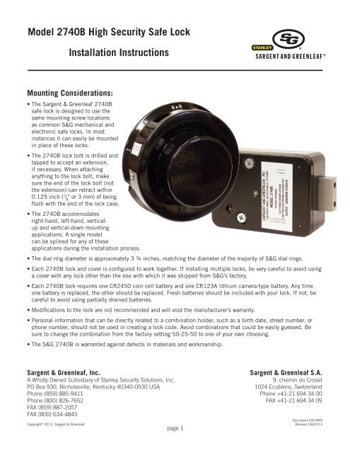
Model 2740B High Security Safe Lock<br />
<strong>Installation</strong> <strong>Instructions</strong><br />
Mounting Considerations:<br />
• The <strong>Sargent</strong> & <strong>Greenleaf</strong> 2740B<br />
safe lock is designed to use the<br />
same mounting screw locations<br />
as common S&G mechanical <strong>and</strong><br />
electronic safe locks. In most<br />
instances it can easily be mounted<br />
in place of these locks.<br />
• The 2740B lock bolt is drilled <strong>and</strong><br />
tapped to accept an extension,<br />
if necessary. When attaching<br />
anything to the lock bolt, make<br />
sure the end of the lock bolt (not<br />
the extension) can retract within<br />
0.125 inch ( 1 / 8<br />
" or 3 mm) of being<br />
flush with the end of the lock case.<br />
• The 2740B accommodates<br />
right-h<strong>and</strong>, left-h<strong>and</strong>, verticalup<br />
<strong>and</strong> vertical-down mounting<br />
applications. A single model<br />
can be splined for any of these<br />
applications during the installation process.<br />
• The dial ring diameter is approximately 3 ¾ inches, matching the diameter of the majority of S&G dial rings.<br />
• Each 2740B lock <strong>and</strong> cover is configured to work together. If installing multiple locks, be very careful to avoid using<br />
a cover with any lock other than the one with which it was shipped from S&G’s factory.<br />
• Each 2740B lock requires one CR2450 coin cell battery <strong>and</strong> one CR123A lithium camera-type battery. Any time<br />
one battery is replaced, the other should be replaced. Fresh batteries should be included with your lock. If not, be<br />
careful to avoid using partially drained batteries.<br />
• Modifications to the lock are not recommended <strong>and</strong> will void the manufacturer’s warranty.<br />
• Personal information that can be directly related to a combination holder, such as a birth date, street number, or<br />
phone number, should not be used in creating a lock code. Avoid combinations that could be easily guessed. Be<br />
sure to change the combination from the factory setting 50-25-50 to one of your own choosing.<br />
• The S&G 2740B is warranted against defects in materials <strong>and</strong> workmanship.<br />
<strong>Sargent</strong> & <strong>Greenleaf</strong>, Inc.<br />
A Wholly Owned Subsidiary of Stanley Security Solutions, Inc.<br />
PO Box 930, Nicholasville, Kentucky 40340-0930 USA<br />
Phone (859) 885-9411<br />
Phone (800) 826-7652<br />
FAX (859) 887-2057<br />
FAX (800) 634-4843<br />
Copyright © 2012, <strong>Sargent</strong> & <strong>Greenleaf</strong><br />
page 1<br />
<strong>Sargent</strong> & <strong>Greenleaf</strong> S.A.<br />
9, chemin du Croset<br />
1024 Ecublens, Switzerl<strong>and</strong><br />
Phone +41-21 694 34 00<br />
FAX +41-21 694 34 09<br />
Document 630-849<br />
Revised 5/8/2013
<strong>Installation</strong> Notes<br />
The <strong>Sargent</strong> & <strong>Greenleaf</strong> model 2740B lock was designed to meet Federal Specification FF-L-2740B. It<br />
can be easily retrofit to most security containers currently in service.<br />
It is necessary to remove only the lock cover for installation. All other parts should remain in place as<br />
received from the manufacturer.<br />
Most safes <strong>and</strong> cabinets will already be prepped for lock installation. In the unlikely event that this is not<br />
the case, locate exact position you want for the lock on the mounting plate. Using the template on the<br />
last page of these instructions, drill <strong>and</strong> tap four holes for the attaching screws ( 1 ⁄ 4<br />
" X 20 or M6 for metric<br />
applications). Using the template, drill a hole for the spindle through the mounting plate. The minimum<br />
spindle hole diameter is 3 ⁄ 8<br />
" (9,5 mm). The optimum hole size is 1 ⁄ 2<br />
" (12,7 mm) diameter.<br />
Wear the included static discharge wrist strap whenever you are about to remove the lock cover, or<br />
whenever the cover is off of the lock body. The strap should be grounded to any bare metal of the<br />
container. It is also recommended that you lay the cover (still in its protective sleeve) on the container,<br />
then touch the container prior to h<strong>and</strong>ling the cover. This should reduce the possibility of static discharge.<br />
It is necessary to remove only the cover when attaching the lock. All other parts should remain in<br />
place as received from the factory. When the cover is off of the lock, h<strong>and</strong>le it carefully. It houses the<br />
microprocessor <strong>and</strong> related circuitry. Do not touch the circuit board.<br />
INSTALLATION INSTRUCTIONS<br />
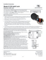
1. Make sure the lock bolt is in the extended position (Figure 1). Carefully remove the lock cover.<br />
CAUTION: H<strong>and</strong>le the cover by its edges. Do not touch the circuit board or pin towers. Any inadvertent contact<br />
may introduce a static discharge which will damage the electronics. Static discharge may cause immediate<br />
lock failure or delayed failure.<br />
CAUTION: Do not attempt to remove the drive cam or the lever.<br />
2. Mount the lock body in place with four 1 ⁄ 4<br />
X 20<br />
attaching screws provided (Figure 1). Apply one<br />
drop of Loctite 242 ® threadlocker to the threads<br />
of each mounting screw near the tip. No Loctite<br />
should be allowed to contaminate the inside of<br />
the lock case. Tighten each mounting screw to<br />
35 inch-pounds (±5 inch-pounds).<br />
Lever<br />
Drive Cam<br />
Figure 1<br />
Extended<br />
Lock Bolt<br />
Mounting Screw Locations<br />
(indicated by white circles)<br />
Opening Index<br />
3. Attach the dial ring to the front of the safe or cabinet by<br />
loosely installing the attaching screws <strong>and</strong> external tooth<br />
lockwashers (included) to hold the dial ring in place for<br />
alignment. The dial ring opening index should be at<br />
the 12 o’clock center position (Figure 3).<br />
Figure 3<br />
page 2
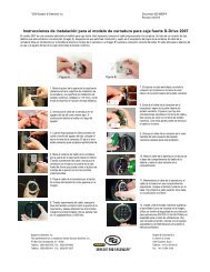
4. Slide the dial spring over the spindle hub at the base of the<br />
spindle. Place the metal dial washer on top of the spring, then<br />
the white washer on top of the metal washer, as shown in the<br />
photo to the right.<br />
5. Hold the drive cam in place in the lock case <strong>and</strong> thread the<br />
dial/spindle assembly into the cam until the dial’s edge is nearly<br />
flush with the top of the dial ring (Figure 4, far right) or until the<br />
dial stops. Make sure the flat washer <strong>and</strong> spring stay in place on<br />
the spindle hub while installing the dial into the cam.<br />
Caution: When threading the dial into the cam, be careful to avoid putting<br />
excessive pressure on the cam by pushing the spindle against it.<br />
6.The alignment of the dial <strong>and</strong> ring is important to the proper operation of the lock. Very good alignment<br />
must be obtained. The dial should be nearly flush <strong>and</strong> centered with the top surface of the dial ring for<br />
true centering (Figure 4). When the dial ring is as perfectly aligned as possible, use masking tape to<br />
hold it in position. Use several pieces of tape to make sure it doesn’t move out of alignment.<br />
Misaligned<br />
Figure 4<br />
Aligned<br />
Dial Edges Nearly<br />
Flush with Ring<br />
Note that the small gap between the dial <strong>and</strong> ring is uneven when the dial ring is misaligned, but is even when the dial ring is properly<br />
aligned. The center of a properly aligned dial ring is in perfect alignment with the center of the spindle hole in the drive cam.<br />
Figure 5<br />
7. Measure <strong>and</strong>/or mark the excess<br />
spindle that projects beyond the<br />
recessed inner surface of the drive<br />
cam (Figure 5). When the spindle<br />
is cut to length, it can be as much<br />
as four threads short of flush with<br />
the surface of the drive cam, but it<br />
cannot extend beyond flush.<br />
Mark Here<br />
Excess Spindle<br />
8. Remove the dial without moving the dial ring out alignment. Remove one dial ring screw <strong>and</strong> lockwasher,<br />
apply a drop of Loctite ® 242 threadlocker to the threads near the tip, re-install the lockwasher <strong>and</strong> screw,<br />
<strong>and</strong> tighten to 14 inch-pounds (±1 inch-pound). Do the same with the remaining screw <strong>and</strong> lockwasher.<br />
Remove the masking tape used to temporarily hold the ring in alignment.<br />
9. Remove the spring <strong>and</strong> washers from the dial. Cut off the excess spindle where you marked it, <strong>and</strong><br />
remove any burrs from the end. You may also find that the spindle threads more easily into the drive<br />
cam if you chamfer the end of the freshly cut spindle slightly. Do not discard the excess spindle piece<br />
as you may use it to seat the spline key later in the installation.<br />
page 3
10. With the dial spring <strong>and</strong> flat washer in place, insert the dial into the lock. Hold the drive cam in<br />
place, positioned for its gate (Figure 6) to receive the fence of the lever assembly, <strong>and</strong> thread the dial<br />
into the cam until the top of the dial is nearly flush with the top surface of the dial ring (Figure 4, far<br />
right) or until the dial stops.<br />
11. Turn the dial counterclockwise until zero is aligned with the opening index of the dial ring. If it was<br />
necessary to turn the dial less than ½ turn, back it out of the drive cam one additional revolution. The<br />
proper spindle spline keyway <strong>and</strong> drive cam spline keyway should now be closely aligned.<br />
Gate<br />
Figure 6<br />
VU Mount<br />
LH Mount<br />
Spline Key<br />
RH Mount<br />
12. After the spline keyways are aligned, insert the spline key as far as you can with your fingers<br />
(sequence in Figure 7). Make sure the spline key is oriented to fit into the recess in the cam. It<br />
will only fit properly one way. The spindle <strong>and</strong> cam are now correctly splined for the way the lock is<br />
mounted (RH, LH, VU, or VD). Use a pin punch or the piece of excess spindle you cut off in Step 9 to<br />
carefully tap the spline key until its underside just touches the top surface of the drive cam. Be very<br />
careful to avoid striking anything other than the spline key. With the spline key fully seated, the dial<br />
must turn freely with no rubbing or interference. Once the spline key is seated, place a tiny amount<br />
(less than a drop) of Loctite ® 242 threadlocker on the threads of the included 2-56 spline key screw.<br />
Place it through the appropriate hole in the cam, then tighten snugly, but do not overtighten.<br />
Figure 7<br />
VD Mount<br />
Note: You can easily remove the spline key after removing the 2-56 screw by<br />
threading the longer of the lock’s two cover screws into the center of the spline<br />
key. As you turn the screw into the spline key, the key will be extracted. This<br />
spline key is reusable.<br />
page 4
13. Install the two batteries in the underside of the cover (Figure 8). The circular coin cell battery goes in<br />
first, positive side up. Then the camera-type battery is inserted as shown. When the coin cell battery<br />
<strong>and</strong> then the main battery are installed, you will hear a beep. If you do not hear the beep, remove<br />
both batteries for one minute, then repeat the installation process. Always insert the coin cell battery<br />
first then the camera-type battery. Ten seconds after the batteries are installed, the lock does a battery<br />
check. If the battery check passes, another beep will be heard. If not, remove both batteries for<br />
one minute, then repeat the battery installation process. If the second battery installation does not<br />
produce the two beeps, repeat the battery installation process using new batteries.<br />
Figure 8<br />
14. Place the cover on the lock body, <strong>and</strong> fasten with the two screws provided. The longer screw goes in<br />
the cover screw opening closest to the change key receptacle (Figure 9). Tighten securely. Your lock<br />
body’s cover screw holes may not be tapped. The cover screws are thread-forming, requiring you to<br />
exert some extra pressure on the screws the first time they are installed.<br />
Figure 9<br />
B<br />
Change Key<br />
Receptacle<br />
15. The Spy-Proof ® dial cover is attached to<br />
the dial ring at two points (Figure 10), one<br />
on each side of the dial ring. The cover is<br />
attached using a 4-40 socket head cap<br />
screw (requiring a 3/32” hex driver) at each<br />
of the two locations. Put one small drop of<br />
Loctite 242 ® threadlocker on the tip of each<br />
cap screw before installing. The cover does<br />
not need to be removed for combination<br />
changing. The Spy-Proof ® cover must be<br />
installed for the lock to meet the Federal<br />
Specification.<br />
Figure 10<br />
page 5
16. Again, check to make sure the dial turns freely.<br />
17. Once you are satisfied that the lock, dial, <strong>and</strong><br />
ring are aligned <strong>and</strong> assembled correctly, use a<br />
small pointed punch to place a tiny locator dot<br />
in the apex of the V-notch on each side of the<br />
dial ring(Figure 11). Be sure to avoid moving the<br />
dial ring while using the punch. The dots can<br />
be used to help re-align the ring if it is bumped<br />
while being moved or during normal service.<br />
Figure 11<br />
18. Place the self-adhesive orange label inside the safe or container, where it is readily visible when the<br />
door or locking drawer is open. For instance, the locking drawer’s inside cover is a good location.<br />
There is also a 5/8” wide label on the same sheet that is sized to fit on the top surface of file drawer<br />
back plates (Figure 12), where it will be in plain view of anyone who opens the drawer.<br />
The lock installation is complete. Refer to the operating instructions for calibration <strong>and</strong><br />
combination setting procedures. The installation is not complete until the lock is calibrated.<br />
Figure 12<br />
LOCK TEMPLATE<br />
SPINDLE HOLE LOCATION<br />
11⁄16 " 13⁄16 "<br />
(17,5 mm)<br />
(20,6 mm)<br />
1 15 " (49,2 mm)<br />
⁄16<br />
RIGHT-HAND MOUNT<br />
AS VIEWED FROM BACK OF LOCK<br />
page 6