Operating Instructions - Sargent and Greenleaf
Operating Instructions - Sargent and Greenleaf
Operating Instructions - Sargent and Greenleaf

You also want an ePaper? Increase the reach of your titles
YUMPU automatically turns print PDFs into web optimized ePapers that Google loves.
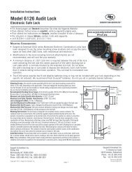
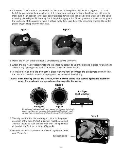
2. A hardened steel washer is attached to the lock case at the spindle hole location (Figure 2). It should<br />
be left in place during lock installation. If it comes loose during shipping or h<strong>and</strong>ling, you will need to<br />
make sure it’s in position in the case cavity provided for it before the lock body is attached to the safe’s<br />
mounting plate (Figure 3). You may find it helpful to apply a thin film of grease or a small spot of glue to<br />
the underside of the washer to make it adhere to the lock case during the mounting process. Do not let<br />
grease or glue creep into the lock case.<br />
Figure 2<br />
Figure 3<br />
2. Mount the lock in place with four 1 ⁄ 4<br />
-20 attaching screws (provided).<br />
3. Attach the dial ring by loosely installing the attaching screws to hold the dial ring in place for alignment.<br />
The dial ring opening index should be at the 12 o’clock center position.<br />
4. To install the dial, hold the drive cam in place with one h<strong>and</strong> <strong>and</strong> thread the dial/spindle assembly into<br />
the cam until the dial comes to a stop against the surface of the dial ring.<br />
Caution: When threading the dial into the cam, do not allow the cam to slide outward against the accelerator<br />
spring. The accelerator spring can be easily damaged in this manner.<br />
Figure 4<br />
Dial Edges<br />
Flush with Ring<br />
Misaligned<br />
Aligned<br />
Note that the small gap between the dial <strong>and</strong> ring is uneven when the dial ring is misaligned<br />
(see arrow above), but is even when the dial ring is properly aligned. The center of a properly<br />
aligned dial ring is in perfect alignment with the center of the spindle hole in the drive cam.<br />
5.The alignment of the dial <strong>and</strong> ring is critical to the proper<br />
operation of the lock. Perfect alignment must be obtained.<br />
The dial should be flush <strong>and</strong> centered with the top surface<br />
of the dial ring for true centering (Figure 4).<br />
Figure 5<br />
6. Measure the excess spindle that projects beyond the drive<br />
cam (Figure 5).<br />
Excess Spindle<br />
page 2